background image


8 /Schematics


8-10

7900 Ventilator- 1503-0151-000  1-97


Figure  8-9


Microcontroller board schematic diagram, page 3 of 10  

SRAM32KX8

U44

SRAM32KX8

U33

SRAM512KX8

U35

SRAM512KX8

U46

200

R161

1%

1/8W

SH1,2

DS

SH1

CS0

SH1

CS1

SH1

CS2

SH1

SIZ0

SH1,2,4,6

RD_WR

U31

74FCT245

R152

4.99K

1/8W

1%

SH6

ENCODER_CLK

SH1,5

RESET

10%
50V

C128
0.22UF

10%
50V

C129
0.22UF

10%
50V

C136
0.22UF

10%
50V

C127
0.22UF

SH1,2,4-8

D[0:15]

D5

D4

D3

D2

D1

D7

D6

D0

D15

D14

D13

D12

D11

D10

D9

D8

C121
10UF

25V

10%

10UF

C119

25V

10%

0.1UF

C114

50V

10%

0.1UF

C108

50V

10%

C130
0.1UF

50V

10%

10UF

C116

25V

10%

10UF

C109

25V

10%

74FCT245

U47

10%
50V

C131
0.1UF

10%
50V

C111
0.1UF

SH1

AS

10%
50V

C115
0.1UF

SH1

FLASH_WR_EN

R162

4.99K

1/8W

1%

BUFR_EN

SH1

IRQ3

SH1

FC2

A16

A17

SH1,2,5,7

A[0:23]

A18

A20

A2

A3

A4

A5

A6

A7

A8

A9

A10

A11

A12

A13

A14

A15

A2

A3

A4

A5

A6

A7

A8

A9

A10

A11

A12

A13

A14

A15

A17

A16

A15

A14

A13

A12

A11

A10

A9

A8

A7

A6

A5

A4

A3

A2

A1

A17

A16

A15

A14

A13

A12

A11

A10

A9

A8

A7

A6

A5

A4

A3

A2

A1

A19

A18

A17

A16

A15

A14

A13

A12

A11

A10

A9

A8

A7

A6

A5

A4

A3

A2

A1

A19

A18

A17

A16

A13

A12

A11

A10

A9

A8

A7

A6

A5

A4

A3

A2

A1

A19

A18

A17

A16

A15

A14

A13

A12

A11

A10

A9

A8

A7

A6

A5

A4

A3

A2

A1

A19

A18

A17

A16

A15

A14

A13

A12

A11

A10

A9

A8

A7

A6

A5

A4

A3

A2

A1

A1

A1

A19

A0

A14

A15

A14

A15

BD7

BD8

BD9

BD10

BD11

BD12

BD13

BD14

BD15

BD0

BD1

BD2

BD3

BD4

BD5

BD6

BD15

BD4

BD1

BD0

BD1

BD2

BD3

BD4

BD5

BD6

BD7

BD8

BD9

BD10

BD11

BD12

BD13

BD14

BD15

BD1

BD2

BD3

BD4

BD5

BD0

BD9

BD10

BD11

BD12

BD13

BD14

BD8

BD15

BD0

BD1

BD2

BD3

BD4

BD5

BD6

BD7

BD8

BD9

BD10

BD11

BD12

BD13

BD14

BD[0:15]

BD0

BD7

BD6

BD5

BD3

BD2

BD8

BD9

BD10

BD11

BD12

BD13

BD14

BD15

BD6

BD7

SH1

BERR

SH1

IACK3

SRAM128KX8

U34

SRAM128KX8

U45

FLASH512KX8

U30

FLASH512KX8

U40

EPM7032

U42

VCC

GND

DQ7

DQ6

DQ5

DQ4

DQ3

DQ2

DQ1

DQ0

A9

A8

A7

A6

A5

A4

A3

A2

A14

A13

A12

A11

A10

A1

A0

W

E

G

28

14

19

18

17

16

15

13

12

11

24

25

3

4

5

6

7

8

1

26

2

23

21

9

10

27

20

22

VCC

GND

DQ7

DQ6

DQ5

DQ4

DQ3

DQ2

DQ1

DQ0

A9

A8

A7

A6

A5

A4

A3

A2

A14

A13

A12

A11

A10

A1

A0

W

E

G

28

14

19

18

17

16

15

13

12

11

24

25

3

4

5

6

7

8

1

26

2

23

21

9

10

27

20

22

VCC

GND

DQ7

DQ6

DQ5

DQ4

DQ3

DQ2

DQ1

DQ0

A9

A8

A7

A6

A5

A4

A3

A2

A18

A17

A16

A15

A14

A13

A12

A11

A10

A1

A0

CE

WE

OE

32

16

21

20

19

18

17

15

14

13

26

27

5

6

7

8

9

10

1

30

2

31

3

28

4

25

23

11

12

22

29

24

VCC

GND

DQ7

DQ6

DQ5

DQ4

DQ3

DQ2

DQ1

DQ0

A9

A8

A7

A6

A5

A4

A3

A2

A18

A17

A16

A15

A14

A13

A12

A11

A10

A1

A0

CE

WE

OE

32

16

21

20

19

18

17

15

14

13

26

27

5

6

7

8

9

10

1

30

2

31

3

28

4

25

23

11

12

22

29

24

G

A1

A2

A3

A4

A5

A6

A7

A8

B7

B8

B6

B5

B4

B3

B2

B1

DIR

19

2

3

4

5

6

7

8

9

12

11

13

14

15

16

17

18

1

VDD

VDD

VDD

VDD

VDD

VDD

VDD

VDD

VDD

VDD

VDD

VDD

VDD

VDD

VDD

G

A1

A2

A3

A4

A5

A6

A7

A8

B7

B8

B6

B5

B4

B3

B2

B1

DIR

1

18

17

16

15

14

13

11

12

9

8

7

6

5

4

3

2

19

VDD

VDD

G

E1

E2

A0

A1

A10

A11

A12

A13

A14

A15

A16

A2

A3

A4

A5

A6

A7

A8

A9

DQ0

DQ1

DQ2

DQ3

DQ4

DQ5

DQ6

DQ7

GND

VCC

W

32

16

21

20

19

18

17

15

14

13

26

27

5

6

7

8

9

10

2

31

3

28

4

25

23

11

12

30

22

29

24

G

E1

E2

A0

A1

A10

A11

A12

A13

A14

A15

A16

A2

A3

A4

A5

A6

A7

A8

A9

DQ0

DQ1

DQ2

DQ3

DQ4

DQ5

DQ6

DQ7

GND

VCC

W

32

16

21

20

19

18

17

15

14

13

26

27

5

6

7

8

9

10

2

31

3

28

4

25

23

11

12

30

22

29

24

VCC

VSS

A18

A17

A16

A15

A14

A13

A12

A11

A10

A9

A8

A7

A6

A5

A4

A3

A2

A1

A0

CE

OE

WE

DQ0

DQ1

DQ2

DQ3

DQ4

DQ5

DQ6

DQ7

12

11

23

25

4

28

29

3

2

1

10

9

8

7

6

5

27

26

13

14

15

17

18

19

20

21

32

16

22

24

31

30

VCC

VSS

A18

A17

A16

A15

A14

A13

A12

A11

A10

A9

A8

A7

A6

A5

A4

A3

A2

A1

A0

CE

OE

WE

DQ0

DQ1

DQ2

DQ3

DQ4

DQ5

DQ6

DQ7

12

11

23

25

4

28

29

3

2

1

10

9

8

7

6

5

27

26

13

14

15

17

18

19

20

21

32

16

22

24

31

30

GCLRN/I

I/O10

I/O5

I/O4

I/O3

I/O2

I/O31

I/O25

I/O26

I/O27

I/O28

I/O29

I/O30

I/O14

I/O15

I/O16

GCLK/I

I/O0

I/O1

I/O11

I/O12

I/O13

I/O17

I/O18

I/O19

I/O20

I/O21

I/O22

I/O23

I/O24

I/O6

I/O7

I/O8

I/O9

OE1N/I

OE2N/I

VDD;3,15,23,35

GND;10,22,30,42

43

1

4

5

16

17

18

19

20

21

24

25

26

27

6

28

29

31

32

33

34

36

37

38

39

7

40

41

8

9

11

12

13

14

44

2

Summary of Contents for Aestiva 7900 SmartVent

Page 1: ...7900 Ventilator Supplemental to the Datex Ohmeda Excel SE and Modulus SE Anesthesia Machine Service Manual Ventilator Software Revision 2 X ...

Page 2: ...1503 0151 000 3 27 97 ...

Page 3: ...1503 0151 000 3 27 97 Ohmeda 7900 Anesthesia Ventilator Supplement to Excel SE and Modulus SE Anesthesia Machine Service Manual Ventilator Software Revision 2 X ...

Page 4: ...1503 0151 000 3 27 97 ...

Page 5: ...14 Output 2 14 Microcontroller Assembly 2 15 Functional Specifications 2 15 Program Memory 2 17 Flash EPROM 2 17 System RAM 2 17 Non Volatile Memory 2 17 Safety Relevant Computing 2 17 Watchdog Systems 2 18 68040 Software Watchdog Timer 2 18 Operating Mode Watchdog 2 18 Error Response Sequence 2 18 DATA Acquisition 2 19 Analog to Digital Converter System 2 19 Multiplexer and Buffer Amplifier 2 20 ...

Page 6: ...w Valve 4 11 Test Gas Inlet Valve GIV 4 12 Gas Inlet Valve FAIL Instructions 4 12 Test Pressure Limit Switch 4 13 Pressure Limit Switch FAIL Instructions 4 14 4 4 Diagnostic tools 4 15 Display A D channels 4 15 Display I O signals 4 16 Display Battery Charge Status 4 17 System Error Log 4 18 System Error Log Codes 4 19 Verify Flow 4 23 4 5 Calibrations 4 24 Calibrate O2 Sensor 4 24 Calibrate Flow ...

Page 7: ...uit board 6 14 Firmware Replacement Procedure 6 16 Software Upload Procedure 6 17 Ohmeda Software Upgrade Tool 6 17 To Install Ohmeda Software Upgrade Tool 6 17 To Install 7900 Software Field Upgrade 6 18 To Perform Software Upgrade 6 18 Microcontroller board 6 18 Removing the front panel 6 19 Replacing the display board 6 19 Replacing the encoder switch 6 21 Removing the battery 6 22 Testing Afte...

Page 8: ...ion Instructions SIB 6 43 6 10 Patient Interface Harness Removal from Excel SE 6 43 6 11 Patient Interface Panel Harness Assembly Removal From Modulus SE 6 44 6 12 SIB Machine INterface Harness Removal 6 46 6 13 Test unit after repair as follows 6 46 7 Illustrated Parts List 7 1 General 7 1 Special Instructions 7 1 Stock Numbers for Replacement Parts 7 1 7 2 7900 SERVICE KITS 7 1 SIB Harnesses 7 1...

Page 9: ...Displays Test CPU 4 4 Test External RAM 4 5 Test Display RAM 4 5 Test Flash ROM 4 6 Test EEPROM 4 7 Test Front Panel 4 8 Test Serial Ports 4 10 Test Flow Valve 4 11 Test Gas Inlet Valve 4 12 Test Pressure Limit Switch 4 13 Display A D Channels 4 15 Discrete I O Signals 4 16 Battery Charge Status 4 17 System Error Log 4 18 Verify Flow Output and Flow Sensors 4 23 Calibrate O2 Sensor 4 24 Calibrate ...

Page 10: ...ct cable 6 19 Figure 6 16 Remove display board 6 20 Figure 6 17 Replacing the encoder 6 21 Figure 6 18 Battery removal 6 22 Figure 6 19 Power Module removal 6 24 Figure 6 20 Power cord removal 6 25 Figure 6 21 Isolation transformer removal 6 26 Figure 6 22 Alarm speaker removal 6 27 Figure 6 23 Power cord inlet connector removal 6 28 Figure 6 24 Regulator removal 6 29 Figure 6 25 Disconnect the fl...

Page 11: ...Patient interface board assembly 7 16 Section 8 Figure 8 1 System connection block diagram 8 2 Figure 8 2 SIB schematic diagram interface cable connections 8 3 Figure 8 3 Patient interface cable Machine side 8 4 Figure 8 4 SIB interface hose and cable routing 8 5 Figure 8 5 7900 SIB schematic diagram page 1 of 2 8 6 Figure 8 6 7900 SIB schematic diagram page 2 of 2 8 7 Figure 8 7 Microcontroller b...

Page 12: ...Notes viii 1503 0151 000 3 27 97 ...

Page 13: ...nces can not warrant or suggest different or additional procedures or re quirements This manual is subject to periodic review update and revision Customers are cau tioned to obtain and consult the latest revision before undertaking any service of the equipment Comments and suggestions on this manual are invited from our customers Send your comments and suggestions to the Manager of Technical Publi...

Page 14: ...mation is on the facing odd numbered page Some terms used in this manual Note A Note provides additional information to clarify a statement in text Important An Important statement is similar to a note but provides a comment of greater emphasis WARNING w w w w A Warning statement with this symbol warns the reader of the possibility of injury to the patient or operator service person CAUTION w w w ...

Page 15: ...ate for a part of the equip ment Z Unlock p ON only for part of the equipment 134oC Autoclavable œ OFF only for part of the equipment Í non autoclavable Direct Current m Type B equipment Alternating Current µ Type BF equipment x Protective earth ground H Type CF equipment y Earth ground w Warning or Caution ISO 7000 0434 r Frame or chassis ground wW Attention consult accompanying docu ments IEC 60...

Page 16: ...ro pean Council Directive 93 42 EEC for medical devices when they are used as specified in their Operation and Mainte nance Manuals The xxxx is the certifica tion number of the Notified Body used by Ohmeda s Quality Systems Ë Minus negative polarity Read top of float P Lamp lighting illu mination XXXX ...

Page 17: ... 4 Test and Troubleshooting must be performed whenever you remove a Ventilator cover to verify that all critical parts of the Ventilator are still operational and within specification WARNING w w w w After the Ventilator has been serviced you must perform Post Service Checkout to verify the entire Anesthesia System is properly functioning before the system can be returned to clinical use WARNING w...

Page 18: ...1 Introduction 1 6 1503 0151 000 5 26 0 Notes ...

Page 19: ... gas composition compensation when Heliox gas is used Figure 2 1 7900 Ventilator Excel SE and Modulus SE Anesthesia System Interface User interface settings are stored in non volatile memory The user may change settings with a simple and secure setting sequence A bellows contains breathing gasses to be delivered to the patient Positive End Expiratory Pressure PEEP is regulated electronically Posit...

Page 20: ...ombined and pass through the ventilator exhalation valve Exhalation valve block is autoclavable Scavenging line runs from the ventilator to the Anesthesia Gas Scavenging Receiver AGSR which scavenges both drive gas and gas released by the bellows pressure relief valve Operates in a Closed Loop configuration during both volume and pressure modes of operation Easier to service fewer components and i...

Page 21: ... 2 3 Supply gas inlet filtered Supply Gas which can be powered from O2 or Air is supplied from the anesthesia machine at a pressure of 241 to 690 kPa 35 to 100 psi This supply gas is filtered through the 5 micron filter and water trap to further eliminate any minute particles of contaminate The filter does not significantly reduce the output pressure on the downstream side of the filter Figure 2 4...

Page 22: ...ure Regulator which regulates the high pressure filtered supply gas oxygen or medical air down to 172 kPa 25 psi Figure 2 6 Flow Control Valve The Flow Control Valve is controlled by the microcontroller Signals are sent to the Flow Control valve which correspond to the generated flow requirements called for by ventilator settings and sensor signals The Flow Control Valve modulates the incoming 25 ...

Page 23: ...ation Manifold Flow Valve Pressure Regulator Inlet Filter Gas Inlet Valve GIV 25 psi Exhaust to Scavenging Valve AGSR 30 mm Port 17 mm Port Bellows Return Gas 25 mm Port Bellows Drive Gas Exhalation Manifold Manifold Pressure Supply Gas Hose 35 100 psi Supply inlet ...

Page 24: ...nerate the required pilot pressure for sealing the exhalation valve dur ing inspiratory periods a DGCV Drive Gas Check Valve is used downstream of the exhalation valve pilot connection This valve is biased shut using an integral weight so as to generate approximately 3 5 cmH2O of bias pressure prior to allow ing flow downstream to the breathing circuit During periods of operation when the ventilat...

Page 25: ...ions providing pressure relief at approximately 110 cmH2O Second the MOBO serves as a backup in the event of a complete blockage of the exhalation valve system relieving circuit pressure at approximately 30 cmH2O under such failure conditions Mechanical Overpressure Bleed Off MOBO Drive Gas Check Valve DGCV Supply Gas Hose Manifold Pressure Transducer Flow Valve Pressure Regulator Inlet Filter Gas...

Page 26: ... reaches a level of approximately 104 cmH2O When either or both of these valves is shut the pilot pressure to the exhalation valve falls rapidly as the flow discharges out the bleed resistor As the pilot pressure is relieved the exhalation valve opens allowing circuit pressure to be relieved The Free Breathing Valve also shown in figure 2 10 allows the patient to take a spontaneous breath The vent...

Page 27: ...bassemblies or modules Microcontroller Printed Circuit Board Front Panel Assembly Power Supply and External I O Interface Board Sealed Lead Acid Battery Power Entry Module and Toroid Sensor interface board The specific function of each of these items is described in subsequent sections Figure 2 11 Electronic functional block diagram ...

Page 28: ...oduct standards Leakage current under 300 micro Amps 132 Vac 60 Hz Output short circuit over voltage protection with automatic recov ery after removal of fault Battery under voltage disconnect function protects charging bad cell Battery under voltage cutoff function protects over discharging 30 minute battery backup operation under normal application Power Requirements Maximum input requirement 54...

Page 29: ...Vac 60Hz 60VA Safety screen thickness 0 005 Cu Isolation hipot voltage 4KV Thermal fuse Thermik S01 110oC Dimension 115 mm diameter x 58 mm thickness Weight 4 8 lb Mounting method Epoxy center hole 0 5 in ID Topology Full wave bridge voltage doubling with auto voltage adapter Rectifier type GBU8D 8A 200V Peak current surge 300A JEDEC Method Power efficiency 92 95 Output filter capacitor 2 x 5600uF...

Page 30: ...ead acid battery charge controller The battery charge circuit charges the sealed lead acid battery anytime ac power is supplied This circuit is based on the Unitrode UC3906 charger controller which monitors and controls both the charging voltage and current through three sepa rate charge states a high current bulk charge state a controlled over charge and a precision float charge This sequence max...

Page 31: ...wn protection The 15V and 5RS_VAUX outputs are 10VA limited and go through 10VA limit circuitry before be ing sent to the SIB board and the pneumatic isolation area Voltage Rails Specifications Outputs Ripples Charge levels Bulk charge over charge and tempera ture compensated floating charge Bulk charge current 250mA c 10 Over charge voltage 14 7V at 25oC Floating charge voltage 13 7V at 25o C Aut...

Page 32: ...ctor This section of the design covers the various inputs and outputs that pass though this connector Each input or output is protected from EMI and ESD in an appro priate manner Sealed Lead Acid Battery A sealed lead acid battery provides battery backup operation for the 7900 ventila tor Batteries meet the following requirements 1 Capacity to operate unit for 30 minutes 2 Good reliability history...

Page 33: ...debug mode Two RS232C serial I O ports Baud rate generator for serial ports Hard power up and soft watchdog error reset generation Data bus buffers Memory and I O decoding Program Memory Safety Relevant Computing Watchdog System Data Acquisition Flow Valve Control Inlet Valve Drive Front Panel Interface Audio Alarm Regulator Output Manifold Pressures Functional Specifications Motorola 68340 Proces...

Page 34: ...cy The external 3 6864 MHz baud rate clock is the time base for this measure ment Counter Timer 2 The second counter timer module can be used as desired by the application soft ware The time base for this timer is the internal 24 11 MHz system clock Serial Communications Module Timing Reference An external 3 6864 MHz clock oscillator serves as the basic timing reference for the Baud Rate Generator...

Page 35: ...801 The electronic hardware design provides the necessary capability for meeting these requirements This includes Digital monitoring of selected control signals Analog monitoring of supply voltages internal control voltages feedback signals from the flow and inlet valves and battery voltage Automatic switch over to battery operation in the event of an inter ruption in ac power Use of the software ...

Page 36: ...ndent from the system clock Logical monitoring is accomplished by assigning a unique watchdog toggle address to each defined mode of operation and detecting a sequence error if due to program flow interruption an operating mode is entered illegally The output of this watchdog is connected to IRQ7 on the 68340 processor Error Response Sequence Errors detected by either watchdog are handled in the f...

Page 37: ...r the A D converter The MAX191 is powered by a 5V supply and protected from over voltage The con verter has an internal 4 096 Volt reference which results in a 1mV Bit resolution A 16 channel multiplexer and buffer amplifier precedes the A D converter The manifold pressure patient pressure inspiratory flow and expiratory flow signal in puts to the multiplexer are filtered with an antialiasing filt...

Page 38: ...is an 8 channel fault protected device and the amplifier used as a buffer to drive the A D converter AD820AR A D Converter The MAX191BCWG is a 12 Bit converter that operates from a single 5 Volt power supply The clock frequency to run the A D converter is 1 048MHz It is derived from the microprocessor system clock With a 1 048MHz clock the conversion time of the A D converter is 13 clock peri ods ...

Page 39: ...ange of the converter is 0 to 4 095 Volts 1mV per LSB The MAX530BCWG has the following dc accuracy specifications Flow Valve Drive Circuit The Flow Valve Drive Circuit supplies flow valve current based on a given DAC in put voltage setting With a 0 to 4 000 Volts input the drive circuit outputs 0 to 1 0 Amps typical into a 3 ohm load This circuit does not require adjustment and is ac curate within...

Page 40: ...ring All of these signals are routed through a single connector from the microcontroller board to the front panel assembly EL Display Controller The S MOS SED1351F Flat Panel display controller drives 480 horizontal pixels by 240 vertical pixels of the front panel EL display Ferrite beads filter the signals from the display controller to the display Video Display Memory This memory consists of one...

Page 41: ...ratory Alarm Signals Part 2 Auditory Alarm Signals The circuit consists of a Yamaha YM2413 Sound Generator and a National Semi conductor LM4860M audio amplifier The sound generator interfaces directly to the CPU and the audio amplifier drives an 8 ohm speaker Manifold Pressures A Setra pressure sensor model 210 PCBM monitors manifold pressure It is lo cated in the oxygen isolation barrier between ...

Page 42: ...450 volts at the transducer and 2 000 volts at the A D controller in the Ven tilator Calibration data is stored in an EEPROM in each of these sensors When directed by system software a differential clock signal is sent to the SIB where it is transformed into a single ended signal for the EEPROMS An enable signal is also sent that turns on 5 Vdc power For noise immunity when the data has been read ...

Page 43: ...h the current transmitter This produces a maximum output of 2 50 volts The 0 to 20 mA current signals are sent to the Ventilator where a voltage drop is produced across 200 ohm resistors for a 0 to 4 00 volt signal to be measured by the A D converter Switch Connections The SIB is used as a connection point for the various switches that indicate the state of the machine These include the O2 flush t...

Page 44: ...2 Theory of Operation 2 26 1503 0151 000 3 27 97 Notes ...

Page 45: ...eturning the anesthesia system to clinical use Failure to do so may result in patient injury 3 1 Test the Ventilator Perform section Preoperative checkout procedure found in the Anesthesia Sys tem Operation and Maintenance Manual 3 2 Test the Anesthesia System The ventilator is an integral part of a complete anesthesia system To be certain the ventilator is functioning correctly it is necessary to...

Page 46: ...3 Post Service Checkout 3 2 1503 0151 000 5 26 0 Notes ...

Page 47: ...r on the work surface of the anesthesia system and reconnect hoses and cables If you are performing routine maintenance it is necessary to complete the entire section It is always necessary to perform section 3 Post Service Checkout after this section WARNING w w w w Post Service Checkout is required after you complete this section You must perform section 3 Post Service Checkout after performing ...

Page 48: ...alve electrical feedback Supply voltage checks Battery voltage checks These tests are run periodically every 30 seconds during normal operation and alarms are associated with each test A failure causes an alarm to display on the screen in the alarm display area See section 4 7 of this chapter and the Appendix in the O M Manual CPU Test Display RAM walking pattern test Data RAM walking pattern test...

Page 49: ...ng mode Ensure the Me chanical Ventilation switch is off Apnea Detect Off and Volume Monitor Standby modes are selected Press the VT Press PEEP and the menu switches at the same time Then push and hold the adjustment knob until the Service Confirma tion menu appears The ventilator enters the service mode without having to pow er down and then back up All data displayed by the ventilator during and...

Page 50: ...lect and confirm settings This knob and the rotary encoder switch attached are also referred to as The Encoder Test CPU The software tests the CPU integer instructions as well as the CPU register s If this test fails the CPU did not perform an integer instruction correctly or the CPU register s have failed Upon FAIL replace the microcontroller board See section 6 ...

Page 51: ...that it wrote is not the same bit pattern that it reads back the test fails Upon FAIL replace the microcontroller board See section 6 Test Display RAM The software tests all of the display RAM memory via a walking bit pattern test It writes a certain bit pattern to a block of memory and then reads that block of mem ory If the bit pattern that was written is not the same bit pattern that it reads b...

Page 52: ...culated for the Flash ROM memory and this value is stored in the Flash ROM This test recalculates the CRC for the Flash ROM and compares it to the value stored in Flash ROM If the value that was calculated does not equal the value that was stored in Flash ROM the test will fail Upon FAIL replace the microcontroller board software a new Flash ROM chip see section 6 ...

Page 53: ...tests all of the EEPROM memory via a bit pattern test It writes a cer tain pattern to a block of memory and then reads that block of memory If the bit pattern that was written is not the same as the bit pattern read back the test fails Upon FAIL replace the microcontroller board ...

Page 54: ...sed and the number next to the button does not reverse highlight the test for that button failed If all of the buttons are pressed and all of the numbers next to the buttons are reverse highlighted the button press test passes The control wheel turn test works the same way The user is prompted to turn the control wheel clockwise and counter clockwise one full turn 16 clicks When the control wheel ...

Page 55: ...4 Tests and Troubleshooting 1503 0151 000 5 26 0 4 9 Panel Switch FAIL Instructions If any of the select buttons or the adjustment knob turn test fails replace the front panel board or the control wheel ...

Page 56: ...rts is echoed directly back to that serial port The test fails if the data sent out is not equal to the data received The status of the test is displayed on the ventilators front screen Serial Port FAIL Instructions The software checks the serial ports to ensure any data sent out is looped back as a direct echo If the returned data is not the same as that sent the ports fails Re place the microcon...

Page 57: ...fails A failure can be caused either by the drive circuit or the flow valve malfunction Check the drive circuit Check the flow valve To check the drive circuit for proper voltage set the flow control to output 120 liters per minute Unplug the connector from the microcontroller board and measure the voltage between the pins it should be approximately 3 volts If the voltage is less than 3 volts meas...

Page 58: ...low 0 5 cmH2O the test fails The software then closes the flow valve and opens the GIV It then reads the A D for the GIV and if the A D for the GIV does not read open the test fails Gas Inlet Valve FAIL Instructions Failure can be caused by the valve malfunctioning or the microcontroller board Use a multimeter to measure the resistance of the GIV solenoid It should be ap proximately 25 ohms If nec...

Page 59: ...value where pres sure continues to increase It then waits for the DPL Drive Pressure Limit switch to trip The pressure at which the DPL switch tripped is indicated This value is cal culated manifold pressure the typical reading is 112 cmH2O not the actual pres sure at the switch If the DPL switch never trips within 15 seconds the test fails If the DPL switch does not trip at a pressure within the ...

Page 60: ...gnal menu and check the DPL Drive Pressure Limit switch status Disconnect pressure switch tubing from manifold and apply 104 4 cmH2O to activate switch and verify switch status If signal status does not agree with switch status disconnect J8 on microcontroller board and measure resistance to determine function of switch ...

Page 61: ...O 0726 0924 3 66 4 68 cmH2O Zero Offset Reading nominal 2050 LSB FLOW CURRENT SENSE 0 to 1 Amp 0000 0FFF 0 1 023 Amps FLOW DAC FEEDBACK 0 to 4 095 Volts 0000 0FFF 0 4 095 Volts INLET VALVE CURRENT SENSE 0 to 200 MA 0943 0F2C 0 235 milliamps Off State Reading 0 to 259 LSB O2 CONCENTRATION 0 to 100 0000 0FFF 1 100 1 225V VOLTAGE REFERENCE 1 220V to 1 229V 04BE 04D3 1 214 1 235 Volts 5 5V TEST 4 988 ...

Page 62: ...ure has exceeded limit switch is N O O2 flush switch status shows on or off when pushing and releasing gas machine O2 flush valve DCGO switch status French machines only either Vent or Aux O2 Supply Pressure Status Pressure indicates there is O2 supply pressure 15V Fail Status indicates analog positive voltage supplies are within range 15V Fail Status indicates analog negative voltage supplies are...

Page 63: ...5 volts the battery charge status displays that the battery is not charged If it is greater than or equal to 12 5 volts the battery charge status displays that the battery is charged Battery Charge Status Battery Charged greater than 12 5 volts Remarks If the battery has been on charge for several hours and you get a battery is not charged display Check the battery in line cable fuse If the fuse i...

Page 64: ...es of information if technical support is required Remarks Note The following Error Log table lists codes for those errors that pertain to ser vice Other codes will display from time to time however these are software in formational codes only and should not be of concern to a service person The software clears the errors that have been logged when Clear Error Log is set so a new listing may be co...

Page 65: ...Switch 1002A Minimum system monitoring caused by a low battery Charge battery if error continues replace battery 1002B Minimum system monitoring caused by incorrect flow valve feedback Reboot the system if problem continues refer to Section 4 Test Flow Valve 1002C Minimum system monitoring caused by incorrect GIV feedback 1 Possible bad gas inlet valve a Disconnect the connector to GIV at J6 Measu...

Page 66: ...e storage external RAM prob lem Reboot the system if problem continues replace the CPU board 10039 All 3 safety relevant parameter areas are different in SRC storage external RAM problem Reboot the system if problem continues replace the CPU board 1003A There are no more EEPROM areas to switch to EEPROM prob lem Reboot the system if problem continues replace the CPU board 1003D Minimum system moni...

Page 67: ...sconnect PSB continue 5 Replace PSB 1004A Minimum system shutdown A D converter failure Reboot the system if problem continues replace the CPU board 1004B Minimum system shutdown CPU test failure Reboot the system if problem continues replace the CPU board 1004C Minimum system shutdown flash EPROM failure Reboot the system if problem continues replace the CPU board 1004D Minimum system shutdown ex...

Page 68: ...thin spec continue Range is 4 988 to 6 09 vdc 2 Replace the CPU board 3 Replace PSB 10059 Minimum system shutdown exter nal reference voltage failed Reboot the system if problem continues replace the CPU board 1005A Minimum system shutdown bootup memory failure Reboot the system if problem continues replace the CPU board 2000D A switch for EEPROM region was requested but there are no more areas to...

Page 69: ...ling the output of the flow valve Gas from the 7900 flow valve exits from three separate areas the two drive hoses and the bleed resistor Independent measurements of flow valve output must capture all gas from these ports or provide for their occlusion Be sure to remove all occlusion devices prior to returning the system to service This tool can provide flow for a check of the flow sensor s span b...

Page 70: ... value at which the O2 sensor was calibrated is stored in the EEPROM The sensor must be calibrated at 21 O2 before calibration at 100 O2 Remarks See operation and maintenance manual Remove the O2 sensor from the 15 mm adapter ensure that the sensor is in an upright position with the cable connector at the top and expose it to room air for approximately 3 minutes The displayed reading should be 21 ...

Page 71: ...he patient interface panel If the A D values are not within the correct tolerance the calibration fails If the calibration passes the A D values at which the inspiratory flow expiratory flow airway pressure and manifold pressure transducers were calibrated at are stored in the EEPROM Remarks Fail indicates a problem with the microcontroller board check for bad differential pressure transducer Chec...

Page 72: ... that the flow sensors are disconnected from the interface panel If the transducer is out of tolerance replace the SIB assembly Remarks Fail indicates a problem with the SIB check for bad differential pressure trans ducer Check the transducer outputs using the Display A D menu Ensure that the flow sensors are disconnected from the interface panel If the transducer is out of tolerance replace the S...

Page 73: ...ndicates a problem with the SIB check for bad differential pressure trans ducer Check the transducer outputs using the Display A D menu Ensure that the flow sensors are disconnected from the interface panel If the transducer is out of tolerance replace the SIB assembly ...

Page 74: ...automated calibration It prompts the user to follow a set of procedural steps to perform the calibration This calibration calculates the pressure sensitivity at 5 different pres sures It uses these five different pressure points along with the inspiratory flow and expiratory flow zero offsets to find the pressure sensitivity If the calculations for the pressure sensitivity are not within the corre...

Page 75: ... reads more than 2 Lpm STOP This indicates a possible leak in the flow sensor pneumatic circuit Skip steps 3 and 4 go directly to step 5 If the pressure is increased further the SIB may be damaged 3 Adjust the APL to read 20 cmH2O on the gauge The flows may jump briefly but should stabilize to read between 5 and 5 Lpm 4 Adjust the APL to read 40 cmH2O on the gauge The flows may jump briefly but sh...

Page 76: ... opened is saved The flow valve is then closed The value at which the flow valve was opened to is then checked to make sure it is within the correct tolerance If it is not the calibration fails If the calibration passes the flow valve calibration point is stored in the EEPROM Remarks Check that the bag vent selection switch is in the vent position If the flow valve calibration test fails immediate...

Page 77: ...ng procedure steps be sides the setup procedure this calibration is completely automated First the soft ware finds the value at which to set the flow valve to get a manifold pressure of 91 92 cmH2O Once it finds this starting point value the automated calibration begins Values shown here are for example only and are not necessarily typical ...

Page 78: ...gas settings Ensure that the breathing circuit gas is exhausting out the scavenging port during the test A negative finding indicates a massive circuit leak Check for proper regulator pressure calibration Ensure that the Flow Valve Cal test was con ducted properly Otherwise failure indicates a calibration problem with the flow valve ...

Page 79: ...e 5 Perform steps 1 6 replacing step 3 with 11 L min 10 L min 9 L min 1 L min Therefore there are 12 points that are calculated for the bleed resistor calibration Calibration points may be greater than the listed cm H2O but if any one of these points is less than the cmH2O listed below calibration fails If the calibration pass es the calculated bleed resistor calibration points are stored in EEPRO...

Page 80: ...r setting must be performed when the Sen sors Cal Due alarm appears in normal operation After the cal setting is properly completed the text for that cal setting will be removed If the Sensor s Cal Due alarm is not active the menu displays the text Sensor s Cal Due alarm not active No calibrations required ...

Page 81: ...he convenience of the service person so they can make changes without having to go back to the main operating menus Select Altitude This provides the user with the means to select the altitude setting Displays Select Drive Gas This provides the user with the means to select the drive gas Displays ...

Page 82: ...his provides the user with the means to select the Heliox mode with systems hav ing ANSI gas systems with Heliox flow tubes installed Set Select Heliox Mode to Available to allow the user to turn Heliox mode on or off during the normal opera tions mode Set Select Heliox Mode to Not Available to prevent the user from turning Heliox mode on during normal operation ...

Page 83: ...oubleshooting 1503 0151 000 5 26 0 4 37 Exit Service Mode Provides the means to exit the service mode via a hardware reset Allows the service person to return to the main operating waveform display and operating menu ...

Page 84: ...ower 3 Power cord fuses 4 50 position cable front panel to microcontroller board 5 Power supply board 6 Membrane switch LED 1 Is the cord plugged in 2 Is the power outlet o k 3 Check power cord fuses in the power module 4 Check cable connection 5 Verify output voltages of power supply Replace power supply board 6 Replace front panel keyboard Alarms display but no audible 1 Audio set too low 2 Spea...

Page 85: ...for high vacuum or blockage 3 Control port plugged or drive gas inlet hose blocked Continuous flow of supply gas before machine is turned ON 1 External hose leak 2 GIV leak 1 Check hose 2 Check GIV solenoid 3 Repair GIV Bellows does not descend during inspi ration 1 Bag APL Vent selector in Bag APL position 2 Drive gas hose disconnected or leaking 1 Place the Bag APL Vent selector in the Vent posi...

Page 86: ...User may still have control of actual Pinspired Conditions or combination of set tings may prevent ventilator from achieving settings Refer to Pressure Sensitivity CAL Fail listed in Section 4 PEEP Not Achieved Pmin PEEP is not within a spe cific window 1 Check tubing connections Rate and or I E Ratio may prevent ventilator from reaching desired PEEP level Heliox Mode is ON Heliox Mode selected Se...

Page 87: ...n expiratory flow sensor 5 Incorrect connection 0 flow on Insp sensor during inspiration or 0 flow on Exp sensor in expira tion after seeing flow in inspira tion 1 Examine check valves free breathing valve and MOBO 2 Check flow sensor locations and tubing connections 3 Check breathing circuit configu ration O2 calibration error O2 not equal to set O2 f 1 O2 greater than 110 Calibrate O2 sensor On ...

Page 88: ...CPU board Measure again If within spec continue 4 Replace CPU board Measure again If still out of spec discon nect PSB continue 5 Replace PSB Flow Valve Failure Minimum System Monitor ing Incorrect feedback Monitoring is still available 1 Reboot ventilator if problem persists continue 2 Disconnect the connector to flow valve at J7 Refer to service mode Test Flow Valve diagnostic in section 4 Gas I...

Page 89: ... outlet DCGO switch is in auxiliary posi tion and language is not French Check switch and language set tings No Battery Battery voltage less than 7 V while running on machine elect power 1 Check inline batt fuse 2 Measure batt volts 12 5 but 16V 3 Replace battery Low Battery Charge Voltage less than 12 5V while running on machine elect power 1 This message should disappear after charging for 12 ho...

Page 90: ...board 4 Replace SIB Manifold pressure sensor failure Minimum system monitor ing Drive pressure limit switch engages and manifold pressure is not greater than 80 cmH2O or bootup calibration of manifold failed Reboot ventilator if problem con tinues replace CPU board Pressure control PEEP disabled Manifold pressure airway pres sure Ventilate in volume mode only without PEEP Ventilator needs service ...

Page 91: ...ify regulator pressure at 25 psig 0 2 psi at 15 L min of flow Set the valve to the 15 L min point using the Verify Flow Menu adjust as necessary 4 Run the Flow Valve Cal menu 5 Run the Cal Bleed Resistor menu 6 Run Test Flow Valve menu 7 Run Test Gas Inlet Valve menu 8 Run Test Pressure Limit Switch menu 9 Remove the Exhalation Manifold Mechanically cycle the MOBO Valve weights see section 6 figur...

Page 92: ...ation Valve Maintenance See the Operation and Maintenance manual for maintenance and parts Supply Gas Inlet Filter 1 O ring install onto filter bowl prior to installation 2 Element assembly 3 Filter bowl Figure 5 1 Supply gas filter Filter assembly with bowl 1503 3319 000 Filter element 1503 3320 000 CAUTION w w w w Cross threading the filter bowl may cause debris to accumulate on the filter resul...

Page 93: ...fold seat the O ring will slip out of place and result in an unacceptable leak Free Breathing Valve Maintenance 1 Remove the deflection tube of the free breathing valve CAUTION w w w w The deflection tube will collapse and tends to close off if it is stored for a period of time without something to hold it open in its original shape 2 Unscrew the valve seat from the bottom of the control module ma...

Page 94: ...rim the tail in line with the bottom edge of the valve seat see figure 5 3 Figure 5 3 Free Breathing Valve flapper replacement 6 Replace the O ring Lubricate with a thin film of KRYTOX 7 Back the seat threads counter clockwise until you feel the thread engage Hand screw the assembly into the manifold 8 Replace the deflection tube on the valve The tube has a rolled edge Ensure that the edge slips o...

Page 95: ...en end wrench 7 mm nut driver for ground wire 10 mm nut driver for large mounting bolt and Nyloc nut Encoder removal 14 mm nut driver for mounting nut Front Panel 2 5 mm hex wrench Display board 7 mm nut driver and 5 5 mm nut driver Microcontroller board 7 mm nut driver offset flat blade screwdriver Power Supply board 7 mm nut driver offset flat blade screwdriver PCB removal Straight blade screwdr...

Page 96: ...900 ventilator from the integrated machine Remove the rear panel from the gas machine ventilator shroud 1 Push the locking clips on the panel toward the center 2 Allow the panel to hang from its retaining cord CAUTION w Do not pull the exhalation valve manifold hoses straight down from the block assembly to remove them Too much force is needed if you pull straight down This added force can cause t...

Page 97: ...SE Figure 6 2 Removing the ventilator from an Excel Modulus SE Anesthesia Gas Machine 4 Unplug the ventilator power cord from the outlet box and thread it out through the opening made by cover removal 5 Disconnect the gas supply hose from the gas machine power outlet and thread it out through the opening made by panel removal 6 Loosen the securing knob under the ventilator on the right hand side 7...

Page 98: ...ventilator Non integrated the anesthesia machine has no mid shelf and the 7900 fits in a shroud mounted to the under side of the top shelf CAUTION w Do not pull the exhalation valve manifold hoses straight down from the block assembly to remove them Too much force is needed if you pull straight down This added force can cause the hoses to release suddenly and possibly cause damage the valve block ...

Page 99: ...anesthesia machine electrical outlet box 7 Ventilator shelf mounting screws mounts the shelf to the bottom of the ventilator chassis 8 Ventilator shroud Mounts onto the top shelf and has a front bezel Figure 6 4 Non integrated 7900 ventilator and mounting tray insertion 1 Remove the dual hose for drive return gas connecting the bellows to the exhalation valve 2 Remove the exhaust hose from the exh...

Page 100: ...he ventilator weighs approximately 40 pounds Use care in its removal 8 Remove the 7900 Ventilator and mounting tray from the anesthesia machine 9 It is necessary to remove the mounting tray to set the ventilator on the service shelf Remove the three mounting screws from the tray 10 See service shelf setup 1 Threaded nut for thumb screw lock bolt one on each side of tray 2 Threaded nut for shipping...

Page 101: ...f on an anti static work station and wear a wrist grounding strap while working on the boards 1 Notch for locking screw on the ventilator 2 Spare locking knob 3 Locking knobs 4 Hold the service shelf in position when unfolded to hold the ventilator while servicing Figure 6 6 Setting up the service shelf 1 Ensure the service shelf is setup on the anesthesia machine s work surface CAUTION w The vent...

Page 102: ... below the mounting rail Slide ventilator toward the front on the rails so locking screw slides in the notch Tighten the securing knob to hold the ventilator to the ser vice shelf CAUTION w The ventilator must sit on the left edge of the gas machine work surface to clear cables and hoses Use care to prevent the ventilator from slip ping off the surface and possibly causing damage to the ventilator...

Page 103: ...s and cover Once the ventilator is secure upon the service shelf and firmly located on the gas machine work surface remove the four screws holding the louvered cover to the ventilator chassis Remove the cover for access to the internal pneumatic assem blies and circuit boards Remove the ground wire from the top cover which connects the cover and chassis Set the cover aside in a safe place ...

Page 104: ...on valve block manifold 4 Ground wires 15 Pneumatic bleed resistor 5 Speaker 16 Mechanical over pressure valve MOBO 6 Isolation transformer 17 Pneumatic quick connect 7 Power supply board 18 Flow control valve 8 Pressure transducer 19 Drive gas check valve 9 Regulator 20 Pneumatic electronic barrier 10 Gas inlet valve GIV 21 Microcontroller board 11 Lock knob for mounting 22 Power module chassis ...

Page 105: ...oard you first must remove the power supply circuit board Removing Power Supply circuit board 1 Battery cable connector J1 2 Alarm speaker connector to microcontroller board J1 3 Ribbon cable microcontroller board to power supply board J2 4 Ribbon cable microcontroller board to power supply board J3 5 Ribbon cable microcontroller board to front panel board J5 Figure 6 10 Disconnecting cables for c...

Page 106: ... Disconnect the ribbon cable connector J5 between the microcontroller board and the front panel circuit board Connector has lock tabs Note the routing of this cable through the slot in the chassis 5 Disconnect the cable connector J1 from the alarm speaker to the microcon troller board 6 Not shown Disconnect the cable connector J4 from the isolation transformer to the power supply board 7 Completel...

Page 107: ...ring screws Finger tighten low torque 2 Power supply board 3 Power supply board connector for isolation transformer cable 4 Key hole slots for angle mounting flange 5 Battery connection J1 to power supply board See step 5 in previous proce dure Figure 6 11 Removing the power supply board ...

Page 108: ...move or repair any circuit board Failure to do so may damage the internal electronics 1 Pneumatic quick connect fitting from main manifold 2 Connector from pressure sensor switch J8 3 Connector from GIV solenoid J6 4 connector from flow valve J7 Figure 6 12 Microcontroller board connector and cable identification around manifold pres sure transducer ...

Page 109: ... the cable connector J6 from the solenoid switch on the gas inlet valve to the microcontroller board 3 Disconnect the cable connector J7 from the flow control valve to the micro controller board 4 Disconnect the pneumatic line from the manifold block to the transducer at the quick connect fitting Cable disconnects in figure 6 10 and the following releases the microcontroller board and the power su...

Page 110: ...and carefully guide the mounted transducer and its pneumatic fitting through the opening in the pneu matic electronic barrier CAUTION w When replacing the microcontroller board be certain that the bottom of the board is aligned and inserted into the three guide slots in the chassis En sure all cables are properly reconnected and mounting screws tightened Firmware Replacement Procedure CAUTION w Th...

Page 111: ...er choose Run 5 Type a setup 6 Follow the Setup instructions on the screen 7 Run the virus scanning software to confirm no known viruses exist on the com puter Note In order to use the Ohmeda Software Upgrade Tool to perform an up grade first install at least one version of field upgrade software on the PC If you do not install at least one version of field upgrade software the Ohmeda Software Upg...

Page 112: ...rade Choose Step by Step and follow the instructions on the screen Confirm the serial port used by the PC and the software version being loaded If these are incorrect choose Can cel and use the Setup menu to change these settings 5 Continue to follow instructions on the screen until the upgrade procedure is com plete Once you are familiar with the upgrade procedure the Quick Upgrade but ton allows...

Page 113: ...s mounting screws Figure 6 14 Front panel removal 3 Lift the front panel up to clear mounting pins and remove it from the chassis Replacing the display board 1 Disconnect the ground wire from the front panel board using the 7 mm nut driver Figure 6 15 Disconnect cable 2 Disconnect ribbon cable between display board and keyboard board Squeeze locking tabs to release connectors ...

Page 114: ...aside for reassembly Figure 6 16 Remove display board 4 Use 5 5 mm nut driver to remove the four hex head mounting nuts 5 Lift out the display board 6 When installing check for debris and or finger prints on the panel face Clean with isopropyl alcohol as necessary ...

Page 115: ...cing the encoder switch 1 Encoder harness connect to front panel 2 Encoder switch 3 Locking washer 4 Tab align tab into hole in circuit board 5 Flat washer 6 Mounting nut use 14 mm wrench 7 Knob spring friction D shaft Figure 6 17 Replacing the encoder ...

Page 116: ...1 000 5 26 0 Removing the battery 1 Foam battery retainer 2 Battery harness route through cutout item 4 3 Battery 4 Hole for battery harness routing 5 Power module bracket assembly with slot for ribbon cable Figure 6 18 Battery removal ...

Page 117: ... not install a battery which is 60 days past the conditioning date If the replacement battery is 60 days past the conditioning date re turn the replacement battery or dispose of according to local regu lations Testing After Maintenance 6 Perform section 4 Test and Calibration and then section 3 Post Service Checkout 7 Charge the battery for 24 hours before returning the ventilator to clinical use ...

Page 118: ...n stud 3 Hex nut mounting on studs Figure 6 19 Power Module removal 5 Use the 1 5 mm hex wrench to remove the screws from the a c power cord re taining clamp Disconnect the power cord from the a c inlet connector See figure 6 20 item 5 6 Use the 7 mm nut driver or open end wrench to disconnect the three ground wires from the power module 7 Use the 7 mm nut driver to loosen the hex nuts on the angl...

Page 119: ... module for removal 1 Threaded holes for mounting screws item 5 to mount the power cord bracket 2 Power cord fuse block 3 Power cord securing bracket 4 Lock washers No 4 external 5 Bracket mounting screws 4x8 mm button socket head Figure 6 20 Power cord removal ...

Page 120: ...unit 1 Disconnect the wire lug connectors from the transformer to the a c connector block 2 Use a 7 mm nut driver to disconnect the ground wire from transformer to power module chassis 3 Use a 10 mm nut driver or wrench to loosen the transformer mounting bolt 4 Hold the transformer with one hand while removing the hex nut and bolt from the center of the transformer 5 Replace the transformer in rev...

Page 121: ... to gain access to the alarm speaker mounting nuts This requires the disconnection of the alarm speaker cable from the microcontroller board J1 2 Clip the cable tie with a diagonal wire cutter item 3 fig 6 22 3 Remove the speaker mounting hex nuts from the studs on the microcontroller board with a 5 mm nut driver 4 Reinstall or replace in reverse order ...

Page 122: ...onnect terminal from the inlet connector as sembly to the transformer Rear connection see figure 6 23 item 4 3 Disconnect the ground wire quick connect terminal from the inlet connector as sembly to the ground lug on power module Middle connection 4 Disconnect the black wire quick connect terminal from the inlet connector as sembly to the transformer front connection see figure 6 23 item 3 5 Depre...

Page 123: ... moved in some cases Removing the non relieving regulator The regulator is replaced as an assembly 1 Phillips head screws 4 DO NOT REMOVE 2 Captive regulator mounting screws 2 Figure 6 24 Regulator removal 1 The regulator is replaced as an assembly Do Not remove the Phillips head screws 4 that hold the regulator together Use the 3 mm hex wrench to loosen the two 2 captive mounting screws 2 Lift ou...

Page 124: ... the cable connector J7 from microcontroller board Figure 6 25 Disconnect the flow control valve cable 2 Use the 3 mm hex wrench to loosen the two 2 captive mounting screws and lift out the flow control valve See figure 6 26 3 Examine the seat and two O rings for damage replace as necessary ...

Page 125: ...6 Repair Procedures 1503 0151 000 5 26 0 6 31 1 Flow control valve cable connector to J7 microcontroller board 2 Captive mounting screws 2 Figure 6 26 Flow control valve removal ...

Page 126: ...id switch removal 1 Disconnect the cable connector J6 from the solenoid switch on the microcon troller board Removing the GIV assembly 2 Use the 3 mm hex wrench to loosen the two 2 captive inlet valve mounting screws 3 Lift the inlet valve solenoid switch assembly out of the ventilator chassis 4 Examine the seat and O rings in the manifold for damage Replace as neces sary Removing the solenoid swi...

Page 127: ...lat blade screwdriver a Remove the retaining ring and valve cap as in step 1 b Push the shuttle fully into the housing with your finger and use the Cross section view 1 Retaining ring 2 U cup seal upper 3 Valve housing 4 Shuttle body 5 U cup seal lower 6 Inlet port access to remove shut tle 7 O ring lower 8 O ring upper 9 Valve cap 1 Retaining ring 2 Valve cap 3 O ring 4 Shuttle with upper U cup 5...

Page 128: ...ve you will see the top of the shuttle move up d Look into the port again and you will see another shoulder Re peat step c but be very careful A slight scratch or nick on this area of the shuttle will cause an unacceptable leak e Use your fingers to remove the shuttle for U cup and lower O ring replacement 1 U cup seal upper 2 Shuttle 3 Apply KRYTOX 4 U cup seal lower Figure 6 29 Detail shuttle an...

Page 129: ... pilot weight cover 3 Captive MOBO mounting screws 4 Threaded for cover screws 5 Cylinder hole for alignment tool and no pilot weight 6 No pilot weight and pressure seal 7 Port with O ring 8 Pressure seal for no pilot weight 9 Diaphragm for pilot weight 10 No pilot weight 11 Pilot weight Figure 6 30 Mechanical Over pressure Bleed Off valve MOBO removal ...

Page 130: ...l operation with the APL switch set to VENT 3 Occlude the Y piece of the patient breathing circuit 4 Place the diaphragm and pilot weight onto the manifold Note When replacing the diaphragm also replace the pilot weight included in the elastomer kit 5 Set the valve housing into the recessed area on the main manifold 6 Align the side of the housing along the back edge of the manifold so it is paral...

Page 131: ...e all occlusions 1 MOBO installation alignment tool 2 Cover mounting screws 4x8 mm 3 Top cover no pilot weight cylinder 4 No pilot weight cylinder 5 Captive MOBO assembly mounting screws 6 MOBO assembly body 7 Port for no pilot weight 8 Port with O ring 9 Port for pilot weight diaphragm 10 7900 main manifold Figure 6 31 MOBO alignment and installation ...

Page 132: ...ess Use a blunt object to push the weights up and then allow them to drop back down See figure 6 32 1 Regulated pressure check port 2 Free breathing valve 3 Supply gas filter bowl 4 Access to MOBO weight no pilot 5 Access to MOBO weight pilot Figure 6 32 Main manifold bottom view exhalation manifold removed CAUTION w w w w Do not use an object that has a sharp or pointed end to lift the weights Th...

Page 133: ...bly 1 Captive mounting screws 2 O ring 3 Alignment hole 4 Pressure switch harness Figure 6 33 Drive gas check valve removal CAUTION w The internal components of the Drive Gas Check Valve are precisely po sitioned Do not attempt to remove or reposition the glass sleeve or pis ton assembly ...

Page 134: ...he manifold for proper orientation 6 Tighten the captive screws Removing the pressure sensing switch assembly 1 Pressure switch mounting screws 2 Cable connector to microcontroller board J8 3 Pneumatic tube to main manifold 4 Main manifold pressure switch pneumatic connection Figure 6 34 Pressure sensing switch removal 1 Disconnect the cable connector J8 from the microcontroller board 2 Disconnect...

Page 135: ...l inspiratory flow sensor to SIB 3 Blue color coded pneumatic hose from interface panel expiratory flow sensor to SIB 4 Natural color coded pneumatic hose interface panel inspiratory flow sensor to SIB SIB assembly 5 SIB assembly mounting screws 6 Machine interface harness to SIB J3 7 Pneumatic tubing from O2 supply to sense detect O2 failure 8 Cable connection to O2 flush valve 9 French units onl...

Page 136: ... disconnect the hoses while the SIB is under pressure This may damage the SIB components Ensure the flow transducers are not pres surized by removing the breathing circuit before disconnecting any of the SIB interconnecting hoses 5 Disconnect the four color coded tubing connectors items 1 4 Figure 6 35 from the SIB Assembly tubing 6 Disconnect connector J1 from P1 on the SIB Assembly item 10 Figur...

Page 137: ...l Harness is replaced as an assembly which includes the flow transducer connectors oxygen sensor connector interface harness transducer tubing with color coded connectors and housing 1 Set the SE System Master Switch to OFF 2 Unplug the system AC power cord from the AC source 3 Disconnect the Inspiratory and Expiratory Flow Transducers from the Interface Panel 4 Disconnect the Oxygen Sensor Harnes...

Page 138: ... transducers are not pres surized by removing the breathing circuit before disconnecting any of the SIB interconnecting hoses 6 11 Patient Interface Panel Harness Assembly Removal From Modulus SE Note The Patient Interface Panel Harness is replaced as an assembly which in cludes the flow transducer connectors oxygen sensor connector interface har ness transducer tubing with color coded connectors ...

Page 139: ... the Vanity panel on the rear of the Anesthesia Machine 10 While supporting the Interface Assembly remove the two M4 keps nuts item 5 Figure 6 37 using a 7 mm nutdriver 11 Carefully route the harness and tubing through the pan to remove the assembly 1 Label patient interface 1001 3464 000 2 Harness SA SIB 1503 3081 000 3 Panel sensor interface Modulus SE 1004 3933 000 4 Spacer sensor interface pan...

Page 140: ...oswitch 7 If applicable remove the two faston connections and the ground wire from the DCGO microswitch 8 Disconnect the harness from the System Master Switch 9 Carefully cut and remove the cable ties that secure the electrical harness to the pan 6 13 Test unit after repair as follows 1 Connect the gas supply hose 2 Connect the cable from the ventilator to the SIB board and the RS232 serial port c...

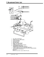
Page 141: ...g bond Use Loctite 24231 screw lock Ohmeda Stock Number 0220 5016 300 When replacing fittings position the barb end in the same direction as the original fitting to make hose connections easier Stock Numbers for Replacement Parts Stock Numbers are identified in the Illustrated Parts List following 7 2 7900 SERVICE KITS See section 09 Appendix for further detail and other parts not shown in this se...

Page 142: ...ew M4 0140 6226 111 4 2 Label set 1503 3027 000 includes fuse label on bottom chassis Figure 7 1 Top cover 1 Washer 9213 0540 003 2 Ground wire 1500 7037 000 3 Hex nut 0144 3717 314 4 Top cover 1503 3031 000 Figure 7 2 Top cover ground wire connections 1 2 2 ...

Page 143: ...lation barrier gasket 1503 3018 000 1 Signal harness 1503 3054 000 2 DC power harness 1503 3053 000 3 Keyboard microboard harness 1503 3052 000 4 Screw M4 x 8 1503 3135 000 5 Main chassis 1503 3040 000 Figure 7 4 Front panel assembly mounting and harnesses 1 2 3 4 5 ...

Page 144: ...27 97 1 Key board front panel 1503 3010 000 2 Bezel 1503 5001 000 3 Keps nuts M4 0144 3717 314 6 Figure 7 5 Front panel key board and bezel 1 EL display kit 1503 8010 000 2 Keps nut M3 0144 3717 302 4 Figure 7 6 EL display panel mounting 1 2 2 2 2 ...

Page 145: ...s nut M4 not shown 0144 3717 314 2 2b Washer M4 not shown 9213 0540 003 2 3 Keyboard microboard harness not shown 1503 3052 000 Figure 7 7 Front panel display assembly harnesses 1 Rotary encoder 1503 3012 000 includes all parts except the knob 2 Knob 1503 3030 000 Figure 7 8 Encoder rotary 16 position with push button switch 2 1 ...

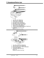
Page 146: ...Power cord receptacle see Figure 7 11 4 Power cord bracket 1503 3070 000 5 Bracket mounting screws 0140 6226 118 2 lockwashers 9213 0540 003 2 6 Threaded hole for shipping screw 7 Locking knob 1301 3018 000 8 Deflector tube for free breathing valve 1503 3110 000 9 Power cord not shown ANSI 1503 3078 000 IEC 1503 3079 000 REV IEC 1503 3080 000 Figure 7 9 Chassis bottom view ...

Page 147: ...set 1503 3027 000 Figure 7 10 Power module mounting 1 Connector AC inlet 1503 3000 000 1a Fuse 2 amp 250V 5x20 mm delayed time not shown 1503 3073 000 2 2 Filter harness 1500 7053 000 2a Keps nut M4 not shown 0144 3717 314 2b Washer M4 not shown 9213 0540 003 3 Transformer assembly 1503 3017 000 see Figure 7 13 4 Bracket power module 1503 3060 000 Figure 7 11 Power module components 3 2 1 1 2 3 4 ...

Page 148: ...Figure 7 12 Alarm speaker Parts 1 through 9 are included with the transformer under part number 1503 3017 000 Figure 7 13 Transformer assembly exploded view 1 Bolt 6 Rubber insulator 2 Nylon sleeve 7 Mounting plate 3 Ground wire 8 Nylon sleeve 4 Mounting location notch 9 Hex nut locking 5 Transformer coil ...

Page 149: ... 000 2 12 Volt battery with harness 1503 3045 000 3 Battery fuse 4 amp inline 1503 3074 000 not shown supplied with battery Figure 7 14 Battery 1 Screw M4 x 8 1503 3135 000 4 2 Bleed orifice 1503 5003 000 2a O ring not shown 0210 0547 300 Figure 7 15 Pneumatic manifold mounting 1 1 2 ...

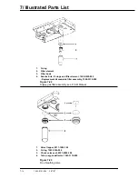
Page 150: ...rive gas check valve assembly 1503 3006 000 2 O ring 1503 3057 000 3 Flow control valve 1503 8013 000 4 Regulator 1503 3004 000 Figure 7 16 Manifold components 1 O rings 1503 3056 000 6 2 O ring 0210 0538 300 1 Figure 7 17 Pneumatic manifold O rings 1 2 3 4 ...

Page 151: ... 8012 000 4 Retaining ring 1500 3158 000 5 GIV cap 1503 5006 000 6 O ring 32 1 ID 35 3 OD 9221 3032 116 7 GIV shuttle with U cups Suttle poppet 1503 5018 000 U cup upper 26 98 OD 20 63 ID 1503 3090 000 U cup lower 17 02 OD 5 33 ID 1503 3089 000 8 O ring 15 6 ID 20 4 OD Vito1503 3108 000 Includes mounting screws 1503 3105 000 2 Figure 7 18 Gas inlet valve ...

Page 152: ...03 5015 000 7 Weight pilot 1503 5014 000 8 Installation alignment tool 1503 3124 000 9 Housing MOBV 1503 5016 000 mounting screw not shown 1503 3105 000 2 Installation alignment tool must be used when replacing seal Included in elastomers service kit 1503 8017 000 When replacing diaphram pilot weight must also be replaced Figure 7 19 MOBO Mechanical Over pressure Bleed Off valve 1 2 9 7 6 5 4 3 8 ...

Page 153: ...wn 0144 3717 314 4 Fitting with o ring 1503 3007 000 2 5 Tubing not shown 0994 6370 010 90 mm long 2 pieces 5a Coupling not shown 1503 3026 000 Figure 7 20 Manifold components continued 1 Screw M4 x 8 button head 0140 6226 118 2 Latch assembly service kit 1503 8014 000 2a Not shown guide springs included 1503 3029 000 3 Test plug 0213 4728 300 4 O2 deflector shield 1503 3109 000 Figure 7 21 Exhala...

Page 154: ... O rings and filter element 1500 3320 000 Replacement kit complete filter assembly 1500 3319 000 Figure 7 22 Supply gas filter assembly see O M Manual 1 Valve flapper 0211 1454 100 2 O ring 1503 3034 000 3 Check valve seat 0207 5590 100 4 Tube oxygen deflector 1503 3110 000 Figure 7 23 Free breathing valve ...

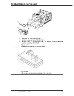
Page 155: ...03 3000 000 2 Exhalation valve assembly 1503 3001 000 3 Exhalation valve kit not shown includes 2 diaphragms 2 o rings gasket and manifold assembly 1503 8004 000 Figure 7 24 Exhalation manifold valve see O M Manual Figure 7 25 SIB Sensor interface board assembly 1503 8009 000 ...

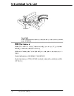
Page 156: ...and tubing SIB Harnesses SIB Machine interface harness 1503 3082 000 connects O2 flush system ON Standby and DCGO on French machines SIB 7900 Ventilator cable 1503 3075 000 connects between the SIB and Venti lator Serial interface cable 7900 RGM 1503 3076 000 Serial Interface cable 1503 3077 000 connects between the ventilator and RS 232 device ...

Page 157: ...gure 8 10 Microcontroller board schematic diagram page 4 of 10 8 11 Figure 8 11 Microcontroller board schematic diagram page 5 of 10 8 12 Figure 8 12 Microcontroller board schematic diagram page 6 of 10 8 13 Figure 8 13 Microcontroller board schematic diagram page 7 of 10 8 14 Figure 8 14 Microcontroller board schematic diagram page 8 of 10 8 15 Figure 8 15 Microcontroller board schematic diagram ...

Page 158: ...8 Schematics 8 2 7900 Ventilator 1503 0151 000 1 97 Figure 8 1 System connection block diagram ...

Page 159: ...8 Schematics 7900 Ventilator 1503 0151 000 1 97 8 3 Figure 8 2 SIB schematic diagram interface cable connections ...

Page 160: ...8 Schematics 8 4 7900 Ventilator 1503 0151 000 1 97 Figure 8 3 Patient interface cable Machine side ...

Page 161: ...xpiratory transducer low 3 Coded black Inspiratory transducer low 4 Patient interface cable connect 5 SIB 7900 Vent interface cable 6 Coded natural Inspiratory transducer high and airway pressure monitor connect 7 SIB assembly housing 8 System ON Standby switch Figure 8 4 SIB interface hose and cable routing ...

Page 162: ...C26 10 0 01UF O2_SENSE SH2 NEWO2_SENSE SH2 MTG3 MTG2 10 25V 10UF C29 1 8W 47 5 1 100PPM R11 PRES_PAT SH1 U7 AD822AR ZJK5103 05 FL3 E2_POWER SH1 REM_ON O2_FLUSH P2 SIGNAL CHAS_GND 51 52 MT2 MT1 1 2 12V 9 8 7 6 1 2 3 4 5 VSET VOUT VIN SHDN LBO LBI GND DD 4 6 1 7 2 3 5 8 IN12 IN11 IN10 IN9 IN8 V IN14 IN13 V IN7 IN6 IN5 IN4 IN3 IN2 IN1 13 12 11 10 9 16 15 14 8 7 6 5 4 3 2 1 12V 2 1 15V 5V 15V 12V 12V ...

Page 163: ...F C19 0 01UF 50V 10 10 50V 0 01UF C33 TP17 J2 E5 5 50V C4 100PF E3 265100 OHMEDA U11 1 8W R2 1 200 1 8W R8 1 200 SDA1_INSP SH1 2 P1 CHAS_GND 16 17 MTG1 TP1 TP3 SDA1_INSP SH1 2 SCLK_PLUS SH1 2 SCLK_MINUS SH1 2 TP4 INSP_RET SH1 7 6 5 3 2 7 4 6 12V 12V OUT COM EXC 2 3 1 SIGNAL SIGNAL 10V FORCE 2V SENSE 2VFS 4MA 4MAADJ ALARM BOOST BW ADJ COM FEEDBACK IOUT VOS1 VOS2 VS 6 7 12 10 11 9 5 4 16 15 8 1 3 2 ...

Page 164: ...50V 10 1 1 8W 4 99K R185 C146 0 1UF 50V 10 10 50V 0 1UF C156 0 1UF C44 50V 10 1 1 8W 33 2 R183 U48 74HC14 74FCT244 U52 U39 MAX488CSA U37 74HC08 1 8W 1 R177 200 200 R44 1 1 8W 1 1 8W 4 99K R150 3 6864MHZ Y1 1 1 8W 4 99K R184 0 1UF C133 50V 10 200 R147 1 1 8W 10 50V 0 1UF C147 TP14 R154 10K 1 8W 1 U37 74HC08 U37 74HC08 U62 DS1232LPS 2 1 8W 1 R142 200 U37 74HC08 R169 1 750 1 8W 1 8W 1 R156 200 200 R1...

Page 165: ... 7 A13 A12 A11 A9 A8 A7 A6 A5 A4 A3 A2 A1 A0 A10 A14 D 0 15 SH1 3 8 D15 D9 D8 D10 D11 D12 D13 D14 D8 D10 D11 D12 D13 D14 D15 D9 QD9 QD8 QD10 QD11 QD12 QD13 QD14 QD15 QD 8 15 SH8 EEPROM_OE EEPROM_WR EEPROM_CE EXT_CS SH5 RESET SH1 5 EPM7032 U51 EPM7032 U27 WE OE CE VSS VCC NC4 NC3 NC2 NC1 I O7 I O6 I O5 I O4 I O3 I O2 I O1 I O0 A9 A8 A7 A6 A5 A4 A3 A2 A10 A1 A0 31 25 23 16 32 2 30 3 27 22 21 20 19 1...

Page 166: ... 11 24 25 3 4 5 6 7 8 1 26 2 23 21 9 10 27 20 22 VCC GND DQ7 DQ6 DQ5 DQ4 DQ3 DQ2 DQ1 DQ0 A9 A8 A7 A6 A5 A4 A3 A2 A14 A13 A12 A11 A10 A1 A0 W E G 28 14 19 18 17 16 15 13 12 11 24 25 3 4 5 6 7 8 1 26 2 23 21 9 10 27 20 22 VCC GND DQ7 DQ6 DQ5 DQ4 DQ3 DQ2 DQ1 DQ0 A9 A8 A7 A6 A5 A4 A3 A2 A18 A17 A16 A15 A14 A13 A12 A11 A10 A1 A0 CE WE OE 32 16 21 20 19 18 17 15 14 13 26 27 5 6 7 8 9 10 1 30 2 31 3 28 4...

Page 167: ...1 8W 1 8W 15K 1 R31 1 8W 15K 1 R110 MAIN_POWER_ON 15K 1 R143 1 8W 15K 1 R144 1 8W 10K R121 1 1 8W 10K R111 1 1 8W 10K R32 1 1 8W DCGO_SW O2_FLUSH_SW BAG_VENT_SW BATT_FULL CONTROL_IACK6 200 R133 1 1 8W R136 1 15K 1 8W U29 74FCT541 TXDA XRESET EXT_SW2 EXT_SW1 1 8W 1 R120 10K CHG_DISABLE SDA1_INSP SH5 SCLK_MINUS SH1 SH1 GIVON_RR E2_POWER SH5 SCLK_PLUS SH1 SDA2_EXP SH5 RXDA_340 SH1 RXDB_340 SH1 IRQ6 S...

Page 168: ...XDOUT7 2N7002 M6 2N7002 M3 2N7002 M5 0 1UF C120 50V 10 1 8W 15K 1 R130 4 99K R131 1 1 8W U21 LM4860M U22 7555 C98 0 01UF 50V 10 C95 0 1UF 50V 10 C83 16V 10 1UF DS_BDM DS_BDM SH1 R164 1 200 1 8W EXT_CS SH2 D0 D1 D2 D3 D4 D5 D7 D6 D 0 15 SH1 4 6 7 D0 D1 D2 D3 D4 D5 D6 D7 200 R118 1 1 8W 3 32K R125 1 8W 1 E1 PJ2 7 68K 1 8W 1 R117 0 22UF 10 25V C93 2 26K 1 1 8W R113 5 11MEG 1 1 8W R112 150PF 10 50V C9...

Page 169: ...1 1 8W 49 9K R218 R221 1 2 26K 1 8W 10 50V C182 0 1UF 0 1UF C179 50V 10 U56 LS7084 74HC14 U58 U57 74HC14 1 8W 2 26K 1 R223 1 8W 2 26K 1 R53 R225 1 2 26K 1 8W 1 8W 2 26K 1 R49 U54 74FCT541 1 8W 1 R212 200 1 8W 1 R213 200 1 1 8W 4 99K R222 1 8W 1 R211 200 J5 R220 1 49 9K 1 8W SP720 U65 PLIMIT_SW STANDBY_SW PEEP_SW VT_SW RATE_SW I E_SW VID3 SH7 VID2 SH7 VID1 SH7 VID0 SH7 VCLK SH7 HS SH7 VS SH7 FP_IN_...

Page 170: ... 200 R210 1 1 8W 200 R190 1 1 8W SED1351F U49 TP16 E3 E2 E7 E6 E8 SRAM32KX8 U53 VDD VDD 15V VDD VDD VDD 15V 5 5V VDD VH_EL 1 10 11 12 13 15 2 3 4 5 6 7 8 9 14 17 18 16 VDD1 VDD2 VSS1 VSS2 DB0 DB1 DB2 DB3 DB4 DB5 DB6 DB7 DB8 DB9 DB10 DB11 DB12 DB13 DB14 DB15 AB0 AB1 AB2 AB3 AB4 AB5 AB7 AB8 AB9 AB10 AB11 AB12 AB13 AB14 AB15 OSC1 OSC2 MPUCLK IOCS IOWR IORD MEMCS MEMWR MEMRD BHE READY MPUSEL RESET VCS...

Page 171: ... D9 SH1 4 6 7 D 0 15 SH2 DAC_ADDR SH2 DAC_WR SH2 MUX1_SEL AD820AR U14 1 8W 11 0K 1 R108 TP5 U59 AD822AR MAX530BCWG U19 MAX191BCWG U18 U10 MAX358CWE MAX358CWE U11 R103 0 1 20K 1 8W MUX_A2 SH2 C32 10 0 1UF 50V TP9 TP12 TP4 TP7 TP8 C26 80 20 2 2UF 25V 25V 2 2UF 80 20 C11 U61 AD822AR SH4 SIB_PWR SH4 V_BATT SH4 I_BATT R93 49 9K 1 8W 1 SH9 MANIFOLD 49 9K R92 1 8W 1 C19 0 15UF 50V 10 C17 0 027UF 50V 10 4...

Page 172: ...NS R71 1 1 00K 1 8W R12 1 1 1 4W C62 10 0 1UF 50V C65 10 0 1UF 50V C66 10 0 1UF 50V C51 10 0 1UF 50V R21 1 1 00K 1 8W R19 1 1 00K 1 8W C52 10 0 1UF 50V U6 AD820AR J7 R5 1 26 1K 1 8W Q1 3906 MJD2955 Q2 1 8W 4 99K 1 R26 R90 1 12 1 1 8W R22 1 16 5K 1 8W R20 1 16 5K 1 8W SH4 PAT_RET SH4 O2 SH4 PRES_PAT 1 4W 200 0 1 R104 R99 0 1 200 1 4W 1 4W 200 0 1 R98 1 4W 200 0 1 R105 CR1 1N4003 FV_DRV SH1 6 HI_DRI...

Page 173: ...67 1 8W 33 2K 0 1 R2 R61 0 1 10 2K 1 8W 10 50V C64 0 1UF 1 8W 33 2K 0 1 R76 1 8W 33 2K 0 1 R88 R17 0 1 17 4K 1 8W R18 0 1 2 87K 1 8W 1 8W 33 2K 0 1 R87 R77 0 1 3 24K 1 8W R15 0 1 118K 1 8W 1 8W 10K 0 1 R74 SH4 P15_FAIL SH4 N15_FAIL AD822AR U7 R24 1 4 32K 1 8W U7 AD822AR R27 1 11K 1 8W U2 AD822AR R25 1 27 4K 1 8W R65 1 2 26K 1 8W R84 1 2 26K 1 8W R72 1 20K 1 8W 1 8W 2 26K 1 R11 R8 1 10K 1 8W R73 1 ...

Page 174: ... IRF540 Q13 MMBT5550LT1 Q16 914 CR44 20 160V 2 2UF C52 1 1 8W 47 5K R42 C30 22UF 35V 20 20 35V 22UF C31 SH1 VBUSS 20 C92 3 3UF 35V 1 8W 1 R108 200 1 1 8W 3 32K R23 200V 2200PF C35 20 1 1 8W R106 3 32K C96 0 1UF 50V 10 20K 1 1 8W R47 20K 1 1 8W R60 SH3 BATT_CUR_SEN 20 160V 330UF C48 10 50V 0 1UF C89 1 1 8W 200 R105 MAX797 U15 1 1 8W 4 75K R133 1 1 8W R107 590 1 1 4W 1 R15 CR42 914 15V 5245 CR39 C11...

Page 175: ...V 0 01UF C7 1 1 8W 47 5K R132 VH_EL VH_EL CR7 ES3B 1 1 8W 200 R20 0 1UF C82 50V 10 R81 2 21K 1 4W 1 0 1UF C75 50V 10 1 1 8W R121 4 75K 10 50V 0 1UF C100 Q5 BSS138 R33 2 00K 1 8W 1 1 8W R35 2 00K 1 E1 AGND AGND 20 35V C40 10UF 20 35V 3 3UF C107 10 50V 0 01UF C37 CR38 DL4004 1 8W R122 0 1 499 3904 Q20 VR2 LP2952IN VR3 MIC29152BT E5 VDD VDD VDD U23 MIC29300 5 0BT 1 1 8W 20K R83 VB SH1 5 1 1 8W 66 5K ...

Page 176: ... SH4 TXDA SH4 1 8W 4 99K 1 R103 U5 AD822AR AD822AR U5 R1 4 99K 1 8W 1 0 1UF C70 50V 10 0 1UF C80 50V 10 50V C4 0 01UF 10 50V C8 0 01UF 10 124K R86 1 8W 1 R72 49 9K 1 8W 1 124K R85 1 8W 1 50V C9 0 01UF 10 R7 499K 1 8W 1 R22 499K 1 8W 1 50V C3 0 01UF 10 R71 49 9K 1 8W 1 BATT_P SH1 BATT_CUR_SEN SH1 35V 10 C103 1UF 35V 10 C97 1UF CR33 914 R55 4 99K 1 8W 1 ISO_RXDB ISO_TXDB HCPL 2531 U18 HCPL 2531 U21 ...

Page 177: ... 1UF 50V CR22 SMBJ16A SP720 U11 50V C58 0 1UF 10 50V C59 0 1UF 10 CR24 SMBJ16A 10 0 1UF C64 50V 10 0 1UF C67 50V 10 0 1UF C66 50V 50V C62 0 1UF 10 50V C61 0 1UF 10 SP720 U8 C74 10 0 1UF 50V CHG_DISABLE SH1 10 0 1UF C60 50V 10 0 1UF C63 50V DCGO J2 SIGNAL CHAS_GND 51 52 P1 O2_RET O2_RET AGND AGND AGND AGND AGND AGND AGND AGND AGND 13 12 11 10 9 8 5 6 3 4 1 2 1 2 3 4 VDD IN12 IN11 IN10 IN9 IN8 V IN1...

Page 178: ...NAL PGND 7 U28 MC14001B SIGNAL VSW 14 SIGNAL PGND 7 U28 MC14001B SIGNAL VSW 14 SIGNAL PGND 7 U28 MC14001B 35V 3 3UF C84 20 C73 0 1UF 50V 10 U7 ICL7665 7555 U10 LS1 BS2620PH 12V 20 C17 1000PF 200V R6 5 4 7 1 4W 1 1 8W 1 00K R66 1 R65 1 00K 1 8W 1 1 8W 1 00K R76 R77 100K 1 8W 1 R67 1 00K 1 8W 1 10 C14 1UF 35V LM2940CT 15 VR1 R87 4 99K 1 8W 1 R95 1 00K 1 8W 1 SIGNAL PGND 7 SIGNAL VSW 14 MC14013B U27 ...

Page 179: ...bellows Screws 3 8 24 x 3 4 2 Label ABA to GMS Knob with stud Truarc ring Shelf ABA to GMS mtg Manifold assembly ABA to GMS Support guide ABA to GMS Screw M5 x 12 Instal inst Arm Assy Vent Bellows Mtg 1503 8003 000 Groove pin Washers flat 2 Screw 10 x 24 x 1 2 3 Lubriplate Filter disposable w tube Washer 6 4 mm ID x 14 3 mm OD Screw M6 Pawl w o pin pivot Plate vent and bellows mtg Flange mtg post ...

Page 180: ...000 Espanol 1503 0143 000 Italiano 1503 0144 000 Japanese 1503 0145 000 Svenska 1503 0152 000 Revision 2 x Domestic 1503 0177 000 Deutsch 1503 0178 000 Francais 1503 0179 000 Espanol 1503 0180 000 Italiano 1503 0181 000 Japanese 1503 0182 000 Swedish 1503 0183 000 Danish 1503 0184 000 Polish 1503 0185 000 Hungarian 1503 0186 000 Czech 1503 0187 000 ...

Page 181: ...801 Fax 81 3 5763 6838 Datex Ohmeda K K Technical Center TRC A Bldg AE 4 8 6 1 1 Heiwajima Ohta ku Tokyo 143 0006 Japan Tel 81 3 5763 6850 Fax 81 3 5763 6852 Korea Datex Ohmeda Pte Ltd 10th Floor Sam Sung Building 36 1 Yoido Dong Youngdeungpo Ku Seoul Korea Tel 82 2 786 7421 Fax 82 2 786 7420 Malaysia Datex Ohmeda Pte Ltd Level 2 Bangunan O Connor 13 Jalan 223 46100 Petaling Jaya Selangor West Mal...

Reviews: