6/ Repair Procedures
1503-0151-000
5/26/0
6-27
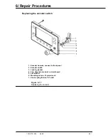
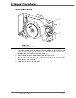
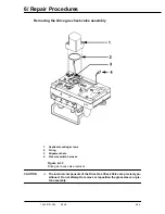
Alarm speaker removal
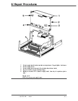
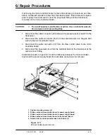
Figure 6-22
Alarm speaker removal
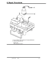
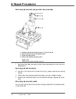
1. The power module must be removed from the chassis to gain access to the
alarm speaker mounting nuts. This requires the disconnection of the alarm
speaker cable from the microcontroller board (J1)
2. Clip the cable tie with a diagonal wire cutter, item 3 fig 6-22.
3. Remove the speaker mounting hex nuts from the studs on the microcontroller
board with a 5 mm nut driver.
4. Reinstall or replace in reverse order.
Summary of Contents for Aestiva 7900 SmartVent
Page 2: ...1503 0151 000 3 27 97 ...
Page 4: ...1503 0151 000 3 27 97 ...
Page 12: ...Notes viii 1503 0151 000 3 27 97 ...
Page 18: ...1 Introduction 1 6 1503 0151 000 5 26 0 Notes ...
Page 44: ...2 Theory of Operation 2 26 1503 0151 000 3 27 97 Notes ...
Page 46: ...3 Post Service Checkout 3 2 1503 0151 000 5 26 0 Notes ...

