6/ Repair Procedures
1503-0151-000
5/26/0
6-15
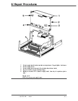
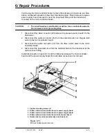
If removing the microcontroller board, remove the following connections, see illus-
tration numbered callouts to follow the steps below listed. Board removal requires
power supply board removal to clear the pneumatic fitting and the transducer
mounted on the microcontroller board.
CAUTION:
w
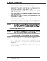
The circuit boards are electrostatic sensitive. Use an anti-static work sta-
tion and wear a wrist grounding strap.
1. Disconnect the cable connector (J8) between the pressure sensor switch to the
transducer.
2. Disconnect the cable connector (J6) from the solenoid switch on the gas inlet
valve to the microcontroller board.
3. Disconnect the cable connector (J7) from the flow control valve to the micro
controller board.
4. Disconnect the pneumatic line from the manifold block to the transducer at the
quick-connect fitting.
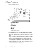
Cable disconnects in figure 6-10 and the following releases the microcontroller
board and the power supply board from all cable connections for removal.
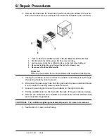
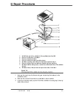
1. Captive mounting screws (4)
2. Ribbon cable microcontroller board to power supply board
3. Ribbon cable microcontroller board to power supply board
4. Ribbon cable microcontroller board to front panel board
5. Guide slots for microcontroller board in chassis (3)
Figure 6-13
Microcontroller board removal
Summary of Contents for Aestiva 7900 SmartVent
Page 2: ...1503 0151 000 3 27 97 ...
Page 4: ...1503 0151 000 3 27 97 ...
Page 12: ...Notes viii 1503 0151 000 3 27 97 ...
Page 18: ...1 Introduction 1 6 1503 0151 000 5 26 0 Notes ...
Page 44: ...2 Theory of Operation 2 26 1503 0151 000 3 27 97 Notes ...
Page 46: ...3 Post Service Checkout 3 2 1503 0151 000 5 26 0 Notes ...

