2/Theory of Operation
1503-0151-000
3/27/97
2-13
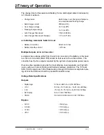
The charge time for the sealed acid battery, from a discharged state to full capacity
is 10 hours maximum.
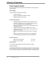
ac to Battery Automatic Switch Circuit
Multiple Outputs dc to dc Converter
A single dc bus voltage, either from the ac to dc converter or the battery, is the input
to a dc to dc converter (MAX 796) similar to that used in the ac/dc section. The
converter has the five outputs required by the system at appropriate power levels.
Post low-drop regulators provide the most effective local regulation and high effi-
ciency with over current limiting and thermal shutdown protection. The 15V and
5RS_VAUX outputs are 10VA limited and go through 10VA limit circuitry before be-
ing sent to the SIB board and the pneumatic isolation area.
Voltage Rails Specifications
Outputs
Ripples
•
Charge levels
Bulk charge, over charge and tempera-
ture compensated floating charge
•
Bulk charge current
250mA (c/10).
•
Over charge voltage
14.7V at 25
o
C
•
Floating charge voltage
13.7V at 25
o
C.
•
Auto Charger Disconnect
7.56 to 8.08Vdc.
•
Auto Charger Disconnect Release
7.71 to 8.71Vdc.
•
Battery connection
Direct on dc bus.
•
Battery standby current
< 200 uA.
•
Digital logic
5 Vdc +3.685% to -3.05% 5W Max.
•
+15V
15 Vdc +15.75 Vdc to + 14.25 Vdc 2W Max.
•
-15V
-15 Vdc -15.75 Vdc to -14.25 Vdc 2W Max.
•
EL Display
10 to 15 Vdc 10W Max.
•
VAUX
5.8 Vdc 6.09 Vdc to 4.99 Vdc 7.7W Max.
•
5 VCC
< 50 mVp-p
•
5.5 Vdc
< 100 mVp-p
•
12 Vdc
< 200 mVp-p
•
±
15V
< 100 mVp-p
Summary of Contents for Aestiva 7900 SmartVent
Page 2: ...1503 0151 000 3 27 97 ...
Page 4: ...1503 0151 000 3 27 97 ...
Page 12: ...Notes viii 1503 0151 000 3 27 97 ...
Page 18: ...1 Introduction 1 6 1503 0151 000 5 26 0 Notes ...
Page 44: ...2 Theory of Operation 2 26 1503 0151 000 3 27 97 Notes ...
Page 46: ...3 Post Service Checkout 3 2 1503 0151 000 5 26 0 Notes ...

