6/ Repair Procedures
6-46
1503-0151-000
5/26/0
6.12. SIB/Machine Interface Harness Removal
1. Set the SE System Master Switch to OFF.
2. Unplug the system AC power cord from the AC source.
3. Remove the Tabletop from the SE. See Excel Service Manual section 5.1,
Modulus SE Service Manual section 5.3.
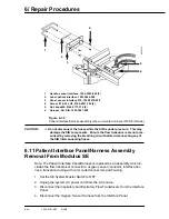
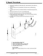
4. Refer to Figure 6-35.
5. Disconnect connector J3 from P3 on the SIB Assembly.
6. Remove the two faston connections and the ground wire from the Oxygen
Flush microswitch.
7. If applicable, remove the two faston connections and the ground wire from the
DCGO microswitch.
8. Disconnect the harness from the System Master Switch.
9. Carefully cut and remove the cable ties that secure the electrical harness to the
pan.
6.13. Test unit after repair as follows
1. Connect the gas supply hose.
2. Connect the cable from the ventilator to the SIB board and the RS232 serial
port connection (if applicable).
3. Plug the ventilator power cord into the gas machine electrical box.
The unit should now operate external of the gas machine using the gas ma-
chine ON/STANDBY switch for ventilator power.
4. Perform Post Service Checkout, Section 3.
Summary of Contents for Aestiva 7900 SmartVent
Page 2: ...1503 0151 000 3 27 97 ...
Page 4: ...1503 0151 000 3 27 97 ...
Page 12: ...Notes viii 1503 0151 000 3 27 97 ...
Page 18: ...1 Introduction 1 6 1503 0151 000 5 26 0 Notes ...
Page 44: ...2 Theory of Operation 2 26 1503 0151 000 3 27 97 Notes ...
Page 46: ...3 Post Service Checkout 3 2 1503 0151 000 5 26 0 Notes ...

