6/ Repair Procedures
6-34
1503-0151-000
5/26/0
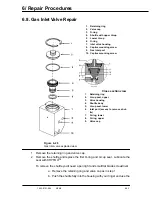
pen-light to look into the gas inlet port (See cross section view,
item 6). You should see a shoulder of the shuttle.
CAUTION:
w
Do not push hard against the shoulder. Do not use an object that has a
sharp or pointed end to lift the shuttle. The sealing area of the shuttle
may be damaged.
c. Insert the screwdriver into the inlet port and very gently lift the
shuttle toward the opening. While looking at the top opening of
the valve, you will see the top of the shuttle move up.
d. Look into the port again and you will see another shoulder. Re-
peat step c, but be very careful. A slight scratch or nick on this
area of the shuttle will cause an unacceptable leak.
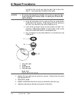
e. Use your fingers to remove the shuttle for U-cup and lower O-ring
replacement.
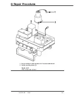
1.
U-cup seal, upper
2.
Shuttle
3.
Apply KRYTOX
4.
U-cup seal, lower
Figure 6-29
Detail shuttle and U-cup seals
3. Replace the second O-ring and second U-cup seal. Lubricate the O-ring and
seal with KRYTOX
™.
4. Reinstall the shuttle.
5. Replace and lubricate the first O-ring as you install the inlet valve cap.
6. Install the retaining ring flat side out (away from the block).
Summary of Contents for Aestiva 7900 SmartVent
Page 2: ...1503 0151 000 3 27 97 ...
Page 4: ...1503 0151 000 3 27 97 ...
Page 12: ...Notes viii 1503 0151 000 3 27 97 ...
Page 18: ...1 Introduction 1 6 1503 0151 000 5 26 0 Notes ...
Page 44: ...2 Theory of Operation 2 26 1503 0151 000 3 27 97 Notes ...
Page 46: ...3 Post Service Checkout 3 2 1503 0151 000 5 26 0 Notes ...

