6/ Repair Procedures
6-36
1503-0151-000
5/26/0
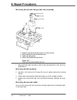
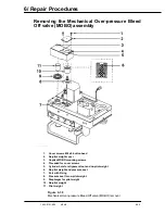
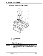
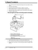
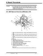
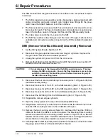
MOBO removal (See figure 6-30)
1. Use the 3 mm hex wrench to loosen the two (2) captive mounting screws hold-
ing the MOBO body (item 2) to the pneumatic manifold.
2. Lift off the MOBO housing from the manifold. Weights will remain on the man-
ifold.
3. Lift the pilot weight (item 11) and the diaphragm (item 9) off the manifold. (Dis-
card the pilot weight if it does not match the weight in the elastomers kit.)
4. Lift off the no-pilot weight assembly (items 8 and 10).
5. Inspect the pressure seal of the no-pilot weight and the diaphragm, item 9. Re-
place as necessary. If replacing the diaphragm, ensure that you install the pilot
weight and diaphragm in the elastomers kit.
6. Item 6 of figure 6-30 is a cross-sectional view of the no-pilot weight, showing
the proper installation of the pressure seal. The seal must be pulled through
the weight and the top trimmed below the top surface.
MOBO installation and
low pressure operation
check
1. Remove the bellows and the pop-off valve from the ABA and reinstall the ABA
housing.
2. Connect the ventilator to the anesthesia machine for normal operation with the
APL switch set to VENT.
3. Occlude the "Y" piece of the patient breathing circuit.
4. Place the diaphragm and pilot weight onto the manifold.
Note: When replacing the diaphragm, also replace the pilot weight included in
the elastomer kit.
5. Set the valve housing into the recessed area on the main manifold.
6. Align the side of the housing along the back edge of the manifold so it is parallel
and equal spaced.
7. Remove the MOBO top cover mounting screws with a 2.5 mm hex wrench and
remove the cover.
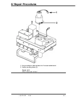
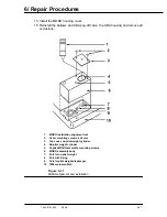
8. Inset the alignment tool (item 1, figure 6-31) into the hole (item 4, figure 6-31)
exposed when the top cover was removed in step 2.
9. Use a 3 mm hex wrench and gently start the threads of the captive mounting
screws. See item 5, figure 6-31. Tighten just enough to hold the assembly but
loose enough so the assembly housing may be moved about on the manifold.
10. Set fresh gas flow to 3 L/min.
11. Occlude the waste gas scavenging port on the exhalation manifold.
12. Observe the circuit pressure gauge on the absorber. Swivel the MOBO hous-
ing around the alignment tool until the pressure reads 20 to 40 cm H
2
O.
13. Tighten the captive housing mounting screws and verify that the circuit pres-
sure remains within the allowable range.
14. Remove the alignment tool and install the high pressure (no pilot) weight.
Summary of Contents for Aestiva 7900 SmartVent
Page 2: ...1503 0151 000 3 27 97 ...
Page 4: ...1503 0151 000 3 27 97 ...
Page 12: ...Notes viii 1503 0151 000 3 27 97 ...
Page 18: ...1 Introduction 1 6 1503 0151 000 5 26 0 Notes ...
Page 44: ...2 Theory of Operation 2 26 1503 0151 000 3 27 97 Notes ...
Page 46: ...3 Post Service Checkout 3 2 1503 0151 000 5 26 0 Notes ...

