6/ Repair Procedures
1503-0151-000
5/26/0
6-41
CAUTION:
w
Do not disconnect the hoses while the SIB is under pressure. This may
damage the SIB components. Ensure the flow transducers are not pres-
surized by removing the breathing circuit before disconnecting any of
the SIB interconnecting hoses.
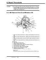
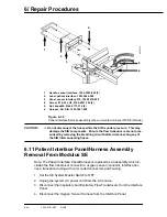
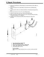
6.9. SIB Removal from Excel/Modulus SE
1.
Black color coded pneumatic hose, interface panel (expiratory flow sensor) to
SIB
2.
Yellow color coded pneumatic hose, interface panel (inspiratory flow sensor) to
SIB
3.
Blue color coded pneumatic hose from interface panel (expiratory flow sensor)
to SIB
4.
Natural color coded pneumatic hose, interface panel (inspiratory flow sensor) to
SIB
SIB assembly
5.
SIB assembly mounting screws
6.
Machine interface harness to SIB J3
7.
Pneumatic tubing from O2 supply to sense/detect O
2
failure
8.
Cable connection to O
2
flush valve
9.
French units only. Cable to DCO select switch
10. Cable from sensor interface panel to SIB J1*
11. Cable from ventilator to SIB J2
• Interface panel mounting may vary depending on machine configuration.
Figure 6-35
SIB assembly cable and pneumatic hose identification (Excel 210SE shown)
Summary of Contents for Aestiva 7900 SmartVent
Page 2: ...1503 0151 000 3 27 97 ...
Page 4: ...1503 0151 000 3 27 97 ...
Page 12: ...Notes viii 1503 0151 000 3 27 97 ...
Page 18: ...1 Introduction 1 6 1503 0151 000 5 26 0 Notes ...
Page 44: ...2 Theory of Operation 2 26 1503 0151 000 3 27 97 Notes ...
Page 46: ...3 Post Service Checkout 3 2 1503 0151 000 5 26 0 Notes ...

