6/ Repair Procedures
1503-0151-000
5/26/0
6-13
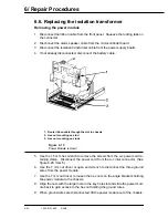
1.
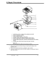
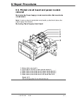
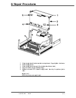
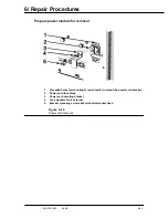
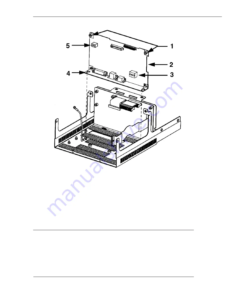
Power supply board has two captive securing screws. Finger tighten, low torque.
2
Power supply board.
3.
Power supply board connector for isolation transformer cable.
4.
Key hole slots for angle mounting flange.
5.
Battery connection (J1) to power supply board. See step 5 in previous proce-
dure.
Figure 6-11
Removing the power supply board
Summary of Contents for Aestiva 7900 SmartVent
Page 2: ...1503 0151 000 3 27 97 ...
Page 4: ...1503 0151 000 3 27 97 ...
Page 12: ...Notes viii 1503 0151 000 3 27 97 ...
Page 18: ...1 Introduction 1 6 1503 0151 000 5 26 0 Notes ...
Page 44: ...2 Theory of Operation 2 26 1503 0151 000 3 27 97 Notes ...
Page 46: ...3 Post Service Checkout 3 2 1503 0151 000 5 26 0 Notes ...

