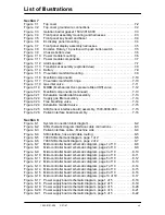
List of Illustrations
1503-0151-000
3/27/97
vii
Section 7
Figure 7-1
Top cover . . . . . . . . . . . . . . . . . . . . . . . . . . . . . . . . . . . . . . . . . . . . . .7-2
Figure 7-2
Top cover ground wire connections . . . . . . . . . . . . . . . . . . . . . . . . . .7-2
Figure 7-3
Isolation barrier gasket, 1503-3018-000 . . . . . . . . . . . . . . . . . . . . . . .7-3
Figure 7-4
Front panel assembly mounting and harnesses . . . . . . . . . . . . . . . . .7-3
Figure 7-5
Front panel key board and bezel . . . . . . . . . . . . . . . . . . . . . . . . . . . . .7-4
Figure 7-6
EL display panel mounting . . . . . . . . . . . . . . . . . . . . . . . . . . . . . . . . .7-4
Figure 7-7
Front panel display assembly harnesses . . . . . . . . . . . . . . . . . . . . . .7-5
Figure 7-8
Encoder, Rotary, 16 position with push button switch. . . . . . . . . . . . .7-5
Figure 7-9
Chassis bottom view . . . . . . . . . . . . . . . . . . . . . . . . . . . . . . . . . . . . .7-6
Figure 7-10 Power module mounting. . . . . . . . . . . . . . . . . . . . . . . . . . . . . . . . . . . .7-6
Figure 7-11 Power module components . . . . . . . . . . . . . . . . . . . . . . . . . . . . . . . . .7-7
Figure 7-12 Alarm speaker . . . . . . . . . . . . . . . . . . . . . . . . . . . . . . . . . . . . . . . . . . .7-7
Figure 7-13 Transformer assembly (exploded view) . . . . . . . . . . . . . . . . . . . . . . . .7-8
Figure 7-14 Battery . . . . . . . . . . . . . . . . . . . . . . . . . . . . . . . . . . . . . . . . . . . . . . . . .7-9
Figure 7-15 Pneumatic manifold mounting . . . . . . . . . . . . . . . . . . . . . . . . . . . . . . .7-9
Figure 7-16 Manifold components . . . . . . . . . . . . . . . . . . . . . . . . . . . . . . . . . . . .7-10
Figure 7-17 Pneumatic manifold O-rings . . . . . . . . . . . . . . . . . . . . . . . . . . . . . . . .7-10
Figure 7-18 Gas inlet valve . . . . . . . . . . . . . . . . . . . . . . . . . . . . . . . . . . . . . . . . . .7-11
Figure 7-19
MOBO (Mechanical Over-pressure Bleed Off) valve . . . . . . . . . . . . .7-12
Figure 7-20
Manifold components (continued) . . . . . . . . . . . . . . . . . . . . . . . . . . .7-13
Figure 7-21
Exhalation manifold latch assembly . . . . . . . . . . . . . . . . . . . . . . . . .7-13
Figure 7-22
Supply gas filter assembly . . . . . . . . . . . . . . . . . . . . . . . . . . . . . . . . .7-14
Figure 7-23
Free breathing valve. . . . . . . . . . . . . . . . . . . . . . . . . . . . . . . . . . . . . .7-14
Figure 7-24
Exhalation manifold valve . . . . . . . . . . . . . . . . . . . . . . . . . . . . . . . . .7-15
Figure 7-25
SIB (Sensor interface board) assembly, 1503-8009-000 . . . . . . . . . .7-15
Figure 7-26
Patient interface board assembly . . . . . . . . . . . . . . . . . . . . . . . . . . . .7-16
Section 8
Figure 8-1
System connection block diagram . . . . . . . . . . . . . . . . . . . . . . . . . . . .8-2
Figure 8-2
SIB schematic diagram interface cable connections . . . . . . . . . . . . . .8-3
Figure 8-3
Patient interface cable - Machine side . . . . . . . . . . . . . . . . . . . . . . . .8-4
Figure 8-4
SIB interface, hose and cable routing . . . . . . . . . . . . . . . . . . . . . . . . .8-5
Figure 8-5
7900 SIB schematic diagram, page 1 of 2 . . . . . . . . . . . . . . . . . . . . .8-6
Figure 8-6
7900 SIB schematic diagram, page 2 of 2 . . . . . . . . . . . . . . . . . . . . .8-7
Figure 8-7
Microcontroller board schematic diagram, page 1 of 10 . . . . . . . . . . .8-8
Figure 8-8
Microcontroller board schematic diagram, page 2 of 10 . . . . . . . . . . .8-9
Figure 8-9
Microcontroller board schematic diagram, page 3 of 10 . . . . . . . . . .8-10
Figure 8-10 Microcontroller board schematic diagram, page 4 of 10 . . . . . . . . . .8-11
Figure 8-11 Microcontroller board schematic diagram, page 5 of 10 . . . . . . . . . .8-12
Figure 8-12 Microcontroller board schematic diagram, page 6 of 10 . . . . . . . . . .8-13
Figure 8-13 Microcontroller board schematic diagram, page 7 of 10 . . . . . . . . . .8-14
Figure 8-14 Microcontroller board schematic diagram, page 8 of 10 . . . . . . . . . .8-15
Figure 8-15 Microcontroller board schematic diagram, page 9 of 10 . . . . . . . . . .8-16
Figure 8-16 Microcontroller board schematic diagram, page 10 of 10 . . . . . . . . .8-17
Figure 8-17 Power supply board schematic diagram, page 1 of 5 . . . . . . . . . . . .8-18
Figure 8-18 Power supply board schematic diagram, page 2 of 5 . . . . . . . . . . . .8-19
Figure 8-19 Power supply board schematic diagram, page 3 of 5 . . . . . . . . . . . .8-20
Figure 8-20 Power supply board schematic diagram, page 4 of 5 . . . . . . . . . . . .8-21
Figure 8-21 Power supply board schematic diagram, page 5 of 5 . . . . . . . . . . . .8-22
Summary of Contents for Aestiva 7900 SmartVent
Page 2: ...1503 0151 000 3 27 97 ...
Page 4: ...1503 0151 000 3 27 97 ...
Page 12: ...Notes viii 1503 0151 000 3 27 97 ...
Page 18: ...1 Introduction 1 6 1503 0151 000 5 26 0 Notes ...
Page 44: ...2 Theory of Operation 2 26 1503 0151 000 3 27 97 Notes ...
Page 46: ...3 Post Service Checkout 3 2 1503 0151 000 5 26 0 Notes ...


