2/Theory of Operation
1503-0151-000
3/27/97
2-21
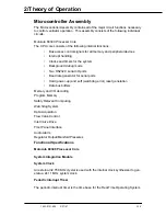
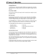
Voltage Reference
Voltage reference is internal to the MAX191BCWG and adjusted with a potentiom-
eter. This reference voltage is buffered and used for the digital to analog converter
reference.
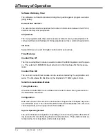
Flow Valve Control
The flow valve control circuit consists of a D/A converter and a voltage to current
conversion circuit.
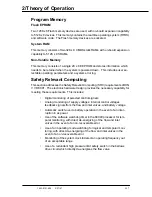
D/A Conversion
The D/A conversion for the flow valve drive circuit is based around the MAXIM
MAX530BCWG 12-Bit DAC. The output of the DAC is fed to an input of the A/D
converter multiplexer allowing the microprocessor to monitor the DAC output.
The MAX530BCWG is a 12-Bit D/A converter operates from a single 5 Volt power
supply. The output range of the converter is 0 to 4.095 Volts (1mV per LSB).
The MAX530BCWG has the following dc accuracy specifications:
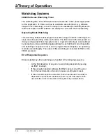
Flow Valve Drive Circuit
The Flow Valve Drive Circuit supplies flow valve current based on a given DAC in-
put voltage setting. With a 0 to 4.000 Volts input, the drive circuit outputs 0 to 1.0
Amps typical into a 3 ohm load. This circuit does not require adjustment and is ac-
curate within
±
2% of full scale.
This circuit also limits the flow valve output to less than 10VA under normal oper-
ation and under a single fault condition. This is a requirement of the international
regulation IEC 601-2-13.
A signal representative of actual drive current is input to the A/D converter to allow
the processor to monitor the current and detect faulty conditions.
•
Integral Nonlinearity
±
1 LSB max
•
Differential Nonlinearity
±
1 LSB max (guaranteed monotonic)
•
Full-Scale Error
±
1 LSB max
•
Zero-Scale Error
+ 4 LSB max
Summary of Contents for Aestiva 7900 SmartVent
Page 2: ...1503 0151 000 3 27 97 ...
Page 4: ...1503 0151 000 3 27 97 ...
Page 12: ...Notes viii 1503 0151 000 3 27 97 ...
Page 18: ...1 Introduction 1 6 1503 0151 000 5 26 0 Notes ...
Page 44: ...2 Theory of Operation 2 26 1503 0151 000 3 27 97 Notes ...
Page 46: ...3 Post Service Checkout 3 2 1503 0151 000 5 26 0 Notes ...

