6/ Repair Procedures
6-42
1503-0151-000
5/26/0
The SIB mounts under the gas machine's work surface in the component compart-
ment area.
1. The SIB is replaced as an assembly and is shipped as a replacement part with
cable connectors and quick connect, color coded, hose fittings for the pneu-
matic hoses that attach between it and the interface.
2. The flow sensors have two pneumatic hose connections and an electronic ca-
ble connection each. The hose connections are color coded so connections be-
tween the interface panel on the gas machine and the SIB are easily made.
3. The cable also connects the O
2
sensor to the SIB.
4. The SIB has another cable that goes out the back of the gas machine to the
ventilator and connects to a cable connector on the 7900 ventilator chassis bot-
tom.
SIB (Sensor Interface Board) Assembly Removal
1. Set the SE System Master Switch to OFF.
2. Disconnect Oxygen pipeline hose and close Oxygen cylinders. Depress the
Oxygen Flush valve to relieve residual pressure.
3. Unplug the system AC power cord from the AC source.
4. Remove the Table top from the SE. See Excel SE Service Manual, section 5.1,
Modulus SE Service Manual Section 5.3.
CAUTION:
w
Do not disconnect the hoses while the SIB is under pressure. This may
damage the SIB components. Ensure the flow transducers are not pres-
surized by removing the breathing circuit before disconnecting any of
the SIB interconnecting hoses.
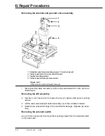
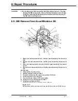
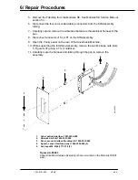
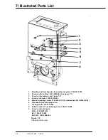
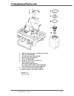
5. Disconnect the four color coded tubing connectors (items 1-4 Figure 6-35) from
the SIB Assembly tubing.
6. Disconnect connector J1 from P1 on the SIB Assembly (item 10, Figure 6-35).
7. Disconnect connector J2 from P2 on the SIB Assembly (item 11, Figure 6-35).
8. Disconnect connector J3 from P3 on the SIB Assembly (item 6, Figure 6-35)
9. Disconnect the O2 tubing from the SIB Assembly (item 7, Figure 6-35).
10. If applicable, remove all gas cylinders
11. Open the Vanity panel on the rear of the Anesthesia Machine
12. If applicable, remove any monitor from the shelf or slide the drawer open to ac-
cess the SIB mounting screws on the underside of the pan.
13. Remove the two mounting screws (Note: On machines that had the 7900 ret-
rofitted in the field, the SIB is mounted to a plate. The Mounting Plate mounting
screws are forward of the mounting screws shown in Figure 6-35, at the two
forward corners of the plate. The SIB is attached to the mounting plate with two
screws that are in the same location as shown in Figure 6-35).
14. Carefully slide the SIB assembly forward until the transducer connections clear
the gauge panel. Remove the assembly from the pan.
Summary of Contents for Aestiva 7900 SmartVent
Page 2: ...1503 0151 000 3 27 97 ...
Page 4: ...1503 0151 000 3 27 97 ...
Page 12: ...Notes viii 1503 0151 000 3 27 97 ...
Page 18: ...1 Introduction 1 6 1503 0151 000 5 26 0 Notes ...
Page 44: ...2 Theory of Operation 2 26 1503 0151 000 3 27 97 Notes ...
Page 46: ...3 Post Service Checkout 3 2 1503 0151 000 5 26 0 Notes ...

