6/ Repair Procedures
6-16
1503-0151-000
5/26/0
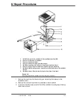
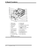
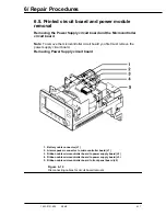
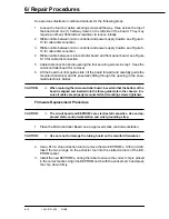
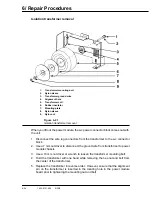
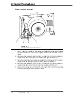
See previous illustration numbered callouts for the following steps.
1. Loosen the four (4) captive securing screws all the way, three across the top of
the board and one (1) half way down on the left side of the board. They may
require an off-set, flat-blade screwdriver to loosen initially.
2. Ribbon cable between micro controller and power supply boards, see Figure 6-
10 for cable disconnection.
3. Ribbon cable between micro controller and power supply boards, see Figure 6-
10 for cable disconnection.
4. Ribbon cable between microcontroller board and front panel board, see Figure
6-10 for cable disconnection.
5. Cable disconnection and loosening the four securing screws in step 1, frees the
microcontroller board for removal.
6. Lift the board out of its guide slots, tilt the board forward and carefully guide the
mounted transducer and its pneumatic fitting through the opening in the pneu-
matic/electronic barrier.
CAUTION:
w
When replacing the microcontroller board, be certain that the bottom of the
board is aligned and inserted into the three guide slots in the chassis. En-
sure all cables are properly reconnected and mounting screws tightened.
Firmware Replacement Procedure
CAUTION:
w
The circuit board and EEPROM’s are electrostatic sensitive. Use and ap-
proved static control workstation and wrist grounding strap.
1. Place the Microcontroller Board on an approved static control workstation.
CAUTION:
w
Use care not to damage the tubing board on the manifold transducer.
2. Use a PLCC chip extraction tool to remove the two EEPROM’s, U30 and U40.
Insert the two prongs on the extractor tool into the slotted corners of the EE-
PROM socket.
3. Install the new EEPROM’s, noting the label to ensure the correct chip is placed
in the correct socket. Align the EEPROM notch with the socket notch and press
the chip down firmly.
Summary of Contents for Aestiva 7900 SmartVent
Page 2: ...1503 0151 000 3 27 97 ...
Page 4: ...1503 0151 000 3 27 97 ...
Page 12: ...Notes viii 1503 0151 000 3 27 97 ...
Page 18: ...1 Introduction 1 6 1503 0151 000 5 26 0 Notes ...
Page 44: ...2 Theory of Operation 2 26 1503 0151 000 3 27 97 Notes ...
Page 46: ...3 Post Service Checkout 3 2 1503 0151 000 5 26 0 Notes ...

