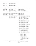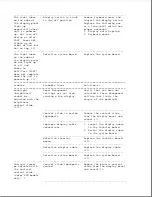
Table 2-10. Tape Drive Computer Checkup Error Codes
===========================================================================
Error Code
Description
Recommended Action
===========================================================================
1900 - xx
Tape ID failed.
The following steps apply to
1900 - xx through 1906 - xx error
1901 - xx
Tape servo write
codes:
failed.
1. Replace the tape cartridge.
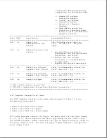
1902 - xx
Tape format failed.
2. Check the switch settings on
the adapter board.
1903 - xx
Tape drive sensor test
3. Check and/or replace the
failed.
signal cable.
4. Replace the tape adapter board
1904 - xx
Tape BOT/EOT test
(if applicable).
failed.
5. Replace the tape drive.
6. Replace the system board.
1905 - xx
Tape read test failed.
1906 - xx
Tape write/read/
compare test failed.
===========================================================================
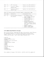
Table 2-11. Video Computer Checkup Error Codes
===========================================================================
Error Code
Description
Recommended Action
===========================================================================
2402 - xx
Video memory test
The following step applies to
failed.
2402 - xx through 2480 - xx error
codes:
2403 - xx
Video attribute test
failed.
Replace the system board.
2404 - xx
Video character set
test failed.
2405 - xx
Video 80 x 25 mode
9 x 14 character cell
test failed.
2406 - xx
Video 80 x 25 mode
8 x 8 character cell
test failed.
2408 - xx
Video 320 x 200 mode
color set 0 test
failed.
2409 - xx
Video 320 x 200 mode
color set 1 test
failed.
2410 - xx
Video 640 x 200 mode
test failed.
2412 - xx
Video gray scale test
failed.
2414 - xx
Video white screen
Summary of Contents for LTE Elite
Page 140: ...7 Remove the hard drive security clips by gently lifting up on them Figure 4 32 ...
Page 248: ...4 Remove the keylock from the outside of the bottom cover Figure 9 5 ...
Page 249: ...5 Slide the plastic keylock barrel out of the bottom cover Figure 9 6 ...
Page 269: ...3 Disconnect the harness extension cable from the system board Figure 9 26 ...
Page 297: ...5 Slide the switch board out of the switch frame Figure 9 52 ...
Page 304: ...5 Replace the eject switch and screw Figure 9 59 ...
Page 309: ...5 Replace the power switch and screw Figure 9 64 ...
Page 348: ...7 Unlock the expansion base keylock Figure D 3 ...
Page 369: ...9 Push the lever toward the back of the convenience base Figure D 16 ...
Page 373: ...5 Slide the computer toward you to remove it from the convenience base ...
Page 387: ......


