


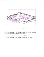


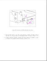


4.21 Battery Pack/Hard Drive Release Latch Assemblies
This section covers removal and replacement procedures for the battery pack
release latch assembly and the hard drive release latch assembly. Each
assembly includes the following:
o Release button
o Latch
o E-clip
o Latch spring
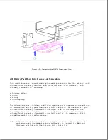
The release buttons, latches, and latch springs work together as assemblies
to release the battery pack and hard drive. The parts for the battery pack
release latch assembly (located in the right side of the computer) are
basically the reverse (a "mirror image") of the parts for the hard drive
release latch assembly (located in the left side of the computer). Both
assemblies work in a similar manner.
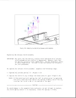
NOTE: Both release latch assemblies come preinstalled on the computer base
enclosure when the computer base enclosure is spared. In addition,
they are available in the Latches Kit (Table 3-8).
Summary of Contents for LTE Elite
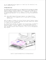
Page 140: ...7 Remove the hard drive security clips by gently lifting up on them Figure 4 32 ...
Page 248: ...4 Remove the keylock from the outside of the bottom cover Figure 9 5 ...
Page 249: ...5 Slide the plastic keylock barrel out of the bottom cover Figure 9 6 ...
Page 269: ...3 Disconnect the harness extension cable from the system board Figure 9 26 ...
Page 297: ...5 Slide the switch board out of the switch frame Figure 9 52 ...
Page 304: ...5 Replace the eject switch and screw Figure 9 59 ...
Page 309: ...5 Replace the power switch and screw Figure 9 64 ...
Page 348: ...7 Unlock the expansion base keylock Figure D 3 ...
Page 369: ...9 Push the lever toward the back of the convenience base Figure D 16 ...
Page 373: ...5 Slide the computer toward you to remove it from the convenience base ...
Page 387: ......


