


Removing the Release Latch Assembly
To remove either the battery pack or hard drive release latch assembly,
complete the following steps:
1. If you are removing the hard drive release latch assembly, remove the
hard drive (Section 4.12).
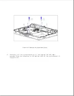
2. Remove the keyboard cover (Section 4.7).
3. Remove the keyboard (Section 4.10).
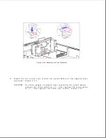
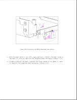
4. Remove the latch spring [1] by holding it with needle-nosed pliers near
its wide end and pulling it straight up out of its slot (Figure 4-57).
5. Remove the e-clip [2] that holds the latch [3] in place and slide the
latch up from its post (Figure 4-57).
6. Remove the release button [4] (Figure 4-57).
>>>>>>>>>>>>>>>>>>>>>>>>>>>>>>>>> CAUTION <<<<<<<<<<<<<<<<<<<<<<<<<<<<<<<<<
To avoid damage to the computer base enclosure, do not attempt to replace
the latch spring unless it is necessary, since the spring is firmly
attached to the enclosure. Leave the existing spring installed unless it is
defective. When it is necessary to replace the spring, remove the spring
straight up out of its slot. Do not twist the spring when removing it.
>>>>>>>>>>>>>>>>>>>>>>>>>>>>>>>>>>>>><<<<<<<<<<<<<<<<<<<<<<<<<<<<<<<<<<<<<<
Summary of Contents for LTE Elite
Page 140: ...7 Remove the hard drive security clips by gently lifting up on them Figure 4 32 ...
Page 248: ...4 Remove the keylock from the outside of the bottom cover Figure 9 5 ...
Page 249: ...5 Slide the plastic keylock barrel out of the bottom cover Figure 9 6 ...
Page 269: ...3 Disconnect the harness extension cable from the system board Figure 9 26 ...
Page 297: ...5 Slide the switch board out of the switch frame Figure 9 52 ...
Page 304: ...5 Replace the eject switch and screw Figure 9 59 ...
Page 309: ...5 Replace the power switch and screw Figure 9 64 ...
Page 348: ...7 Unlock the expansion base keylock Figure D 3 ...
Page 369: ...9 Push the lever toward the back of the convenience base Figure D 16 ...
Page 373: ...5 Slide the computer toward you to remove it from the convenience base ...
Page 387: ......


