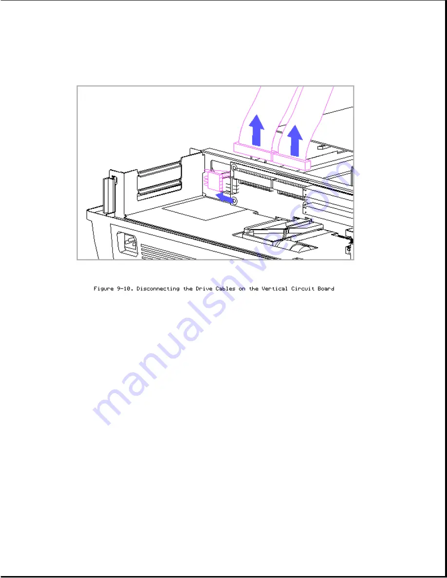
NOTE: The vertical circuit board and the drive signal cables are labeled to
help match the correct connectors. Refer to Section 9.15 for more
information on drive cables.
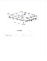
4. Lift the expansion board cage vertically to remove it from the expansion
base (Figure 9-11).
NOTE: The expansion board cage is "keyed" to ride inside grooves that are
in the three cage support posts.
When removing the expansion board cage, the edge connectors on the vertical
circuit board disconnect from the system board.
Summary of Contents for LTE Elite
Page 140: ...7 Remove the hard drive security clips by gently lifting up on them Figure 4 32 ...
Page 248: ...4 Remove the keylock from the outside of the bottom cover Figure 9 5 ...
Page 249: ...5 Slide the plastic keylock barrel out of the bottom cover Figure 9 6 ...
Page 269: ...3 Disconnect the harness extension cable from the system board Figure 9 26 ...
Page 297: ...5 Slide the switch board out of the switch frame Figure 9 52 ...
Page 304: ...5 Replace the eject switch and screw Figure 9 59 ...
Page 309: ...5 Replace the power switch and screw Figure 9 64 ...
Page 348: ...7 Unlock the expansion base keylock Figure D 3 ...
Page 369: ...9 Push the lever toward the back of the convenience base Figure D 16 ...
Page 373: ...5 Slide the computer toward you to remove it from the convenience base ...
Page 387: ......


