


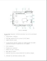


VBatt1 Circuits
The VBatt1 circuits provide 10 to 18.5 volts to the following:
o Computer (while docked)
o Docking mechanism
VBatt2 Circuits
The VBatt2 circuits provide 10 to 18.5 volts to the following:
o Battery charger in expansion base
o Voltage regulator on the expansion base system board, which converts 18.5
volts to 5 volts for the microcontroller, sensors, and wiring harness.
NOTE: The microcontroller controls the VBatt2 circuits.
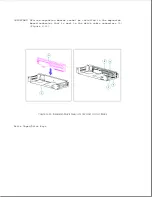
Power-Up Sequencing
The VBatt1 and VBatt2 circuits power up whenever the expansion base is
connected to external power, whether the expansion base is on or off.
This
allows a battery pack to be charged both in the computer and the expansion
base while power is off to the rest of the system.
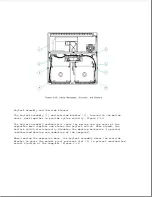
The main expansion base circuits do not power up until the computer is
fully docked and the power switch is pressed. Once this happens, the
controller sends out a power-up signal to the main expansion base circuits
and a power-up signal to the docked computer.
NOTE: When a Compaq LTE Lite is docked in the expansion base, power for the
system can be turned on only with the expansion base power switch.
When a Compaq LTE Elite is docked in the expansion base, power can be
turned on with either the expansion base power switch or the computer
power switch.
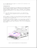
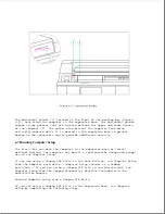
Docking Mechanism
Summary of Contents for LTE Elite
Page 140: ...7 Remove the hard drive security clips by gently lifting up on them Figure 4 32 ...
Page 248: ...4 Remove the keylock from the outside of the bottom cover Figure 9 5 ...
Page 249: ...5 Slide the plastic keylock barrel out of the bottom cover Figure 9 6 ...
Page 269: ...3 Disconnect the harness extension cable from the system board Figure 9 26 ...
Page 297: ...5 Slide the switch board out of the switch frame Figure 9 52 ...
Page 304: ...5 Replace the eject switch and screw Figure 9 59 ...
Page 309: ...5 Replace the power switch and screw Figure 9 64 ...
Page 348: ...7 Unlock the expansion base keylock Figure D 3 ...
Page 369: ...9 Push the lever toward the back of the convenience base Figure D 16 ...
Page 373: ...5 Slide the computer toward you to remove it from the convenience base ...
Page 387: ......


