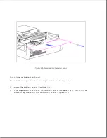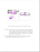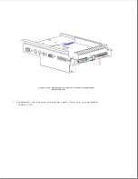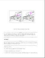
IMPORTANT: When replacing the system board/battery charging compartment
assembly, ensure that the release latch on the AUI connector
lock is folded flat against the RJ-45 connector and that the
harness extension cable is positioned to allow it to connect
to the sensor cable harnesses.
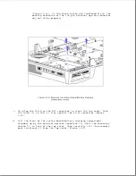
In addition, you must press
in the center of the external options connector to enable the
system board to seat properly.
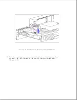
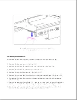
11. Turn the assembly over and remove the battery bezel [1] from the
battery charging compartment by gently releasing the two plastic
retaining tabs that hold them together (Figure 9-23).
Summary of Contents for LTE Elite
Page 140: ...7 Remove the hard drive security clips by gently lifting up on them Figure 4 32 ...
Page 248: ...4 Remove the keylock from the outside of the bottom cover Figure 9 5 ...
Page 249: ...5 Slide the plastic keylock barrel out of the bottom cover Figure 9 6 ...
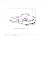
Page 269: ...3 Disconnect the harness extension cable from the system board Figure 9 26 ...
Page 297: ...5 Slide the switch board out of the switch frame Figure 9 52 ...
Page 304: ...5 Replace the eject switch and screw Figure 9 59 ...
Page 309: ...5 Replace the power switch and screw Figure 9 64 ...
Page 348: ...7 Unlock the expansion base keylock Figure D 3 ...
Page 369: ...9 Push the lever toward the back of the convenience base Figure D 16 ...
Page 373: ...5 Slide the computer toward you to remove it from the convenience base ...
Page 387: ......

