o Network Drivers diskette - Use to install network drivers.
o SCSI Drivers diskette - Use to install SCSI drivers (Section F.6).
o Supplemental Programs diskette - Use to copy the updated EXTDISK.SYS file
to the hard drive (Section C.4). EXTDISK.SYS is the only file you need on
this diskette.
Docking the Compaq LTE Lite
To dock the Compaq LTE Lite in the Compaq SmartStation, complete the
following steps:
1. Connect the expansion base to an electrical outlet.
2. Turn off and disconnect any external devices that are connected to the
computer.
3. Remove any cable or option that extends beyond the enhanced option
slot.
>>>>>>>>>>>>>>>>>>>>>>>>>>>>>>>>> CAUTION <<<<<<<<<<<<<<<<<<<<<<<<<<<<<<<<<
If a cable or option extends beyond the Enhanced Option Slot when docking
or undocking the computer, the option connectors may be damaged.
>>>>>>>>>>>>>>>>>>>>>>>>>>>>>>>>>>>>><<<<<<<<<<<<<<<<<<<<<<<<<<<<<<<<<<<<<<
4. Attach the SmartStation Adapter to the Compaq LTE Lite (refer to
"Connecting the SmartStation Adapter").
5. Turn the computer off.
NOTE: The computer cannot be docked while in Standby. If the computer
is in Hibernation, you may be prompted either to reboot or to
eject and restore the Hibernation state. However, with some
configurations, you will receive no error message if attempting
to dock while in Hibernation, even though you will not have use
of all optional devices connected to the expansion base.
6. If the monitor support cover is being used, close the computer display.
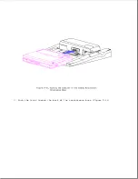
7. Unlock the expansion base keylock (Figure D-3).
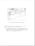
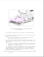
8. Slide the computer forward in the docking bay until you feel the
computer being pulled from your hands (Figure D-8).
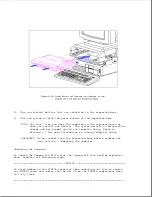
NOTE: A beep indicates that the computer cannot be docked. Verify that
you have completed steps 1 through 8 and try again. If the
expansion base still beeps, refer to Chapter 7 for
troubleshooting information.
Summary of Contents for LTE Elite
Page 140: ...7 Remove the hard drive security clips by gently lifting up on them Figure 4 32 ...
Page 248: ...4 Remove the keylock from the outside of the bottom cover Figure 9 5 ...
Page 249: ...5 Slide the plastic keylock barrel out of the bottom cover Figure 9 6 ...
Page 269: ...3 Disconnect the harness extension cable from the system board Figure 9 26 ...
Page 297: ...5 Slide the switch board out of the switch frame Figure 9 52 ...
Page 304: ...5 Replace the eject switch and screw Figure 9 59 ...
Page 309: ...5 Replace the power switch and screw Figure 9 64 ...
Page 348: ...7 Unlock the expansion base keylock Figure D 3 ...
Page 369: ...9 Push the lever toward the back of the convenience base Figure D 16 ...
Page 373: ...5 Slide the computer toward you to remove it from the convenience base ...
Page 387: ......


