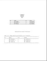
Table A-3. External Monitor Connector
===========================================================================
Pin
Signal
Pin
Signal
===========================================================================
1
Red Analog
9
Not connected
2
Green Analog
10
Ground
3
Blue Analog
11
Not connected
4
Not connected
12
Not connected
5
Ground
13
Horizontal Sync
6
Ground Analog
14
Vertical Sync
7
Ground Analog
15
Not connected
8
Ground Analog
Shell
Ground
===========================================================================
Summary of Contents for LTE Elite
Page 140: ...7 Remove the hard drive security clips by gently lifting up on them Figure 4 32 ...
Page 248: ...4 Remove the keylock from the outside of the bottom cover Figure 9 5 ...
Page 249: ...5 Slide the plastic keylock barrel out of the bottom cover Figure 9 6 ...
Page 269: ...3 Disconnect the harness extension cable from the system board Figure 9 26 ...
Page 297: ...5 Slide the switch board out of the switch frame Figure 9 52 ...
Page 304: ...5 Replace the eject switch and screw Figure 9 59 ...
Page 309: ...5 Replace the power switch and screw Figure 9 64 ...
Page 348: ...7 Unlock the expansion base keylock Figure D 3 ...
Page 369: ...9 Push the lever toward the back of the convenience base Figure D 16 ...
Page 373: ...5 Slide the computer toward you to remove it from the convenience base ...
Page 387: ......


