


NOTE: The screw that attaches the eject switch to the top cover is also
used to attach the horizontal guide.
Power Switch Side
To replace the horizontal guide and spring for the power switch side,
complete the following steps:
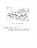
1. Position the spring so that the legs of the spring are on the top [1]
(Figure 9-60).
2. With the curved surface of the horizontal guide [2] facing left, place
the spring post of the horizontal guide [3] in the coil of the spring
[4].
Ensure that both legs of the spring are to the right of the
horizontal guide (Figure 9-60).
Summary of Contents for LTE Elite
Page 140: ...7 Remove the hard drive security clips by gently lifting up on them Figure 4 32 ...
Page 248: ...4 Remove the keylock from the outside of the bottom cover Figure 9 5 ...
Page 249: ...5 Slide the plastic keylock barrel out of the bottom cover Figure 9 6 ...
Page 269: ...3 Disconnect the harness extension cable from the system board Figure 9 26 ...
Page 297: ...5 Slide the switch board out of the switch frame Figure 9 52 ...
Page 304: ...5 Replace the eject switch and screw Figure 9 59 ...
Page 309: ...5 Replace the power switch and screw Figure 9 64 ...
Page 348: ...7 Unlock the expansion base keylock Figure D 3 ...
Page 369: ...9 Push the lever toward the back of the convenience base Figure D 16 ...
Page 373: ...5 Slide the computer toward you to remove it from the convenience base ...
Page 387: ......


