Appendix A - Connector Pin Assignments
Introduction
This appendix provides connector pin assignment tables for the Compaq LTE
Elite and the SmartStation expansion base. For more information on
connectors, refer to Section 1.5 for connectors located on the computer and
to Section 6.5 for connectors located on the expansion base.
NOTE: The signals in all tables of this appendix are considered active high
unless otherwise indicated by an asterisk (*).
A.1 Connector Pin Assignments
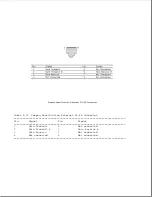
Table A-1. Parallel Connector
===========================================================================
Pin
Signal
Pin
Signal
===========================================================================
1
Strobe *
14
Auto Linefeed *
2
Data Bit 0
15
Error *
Summary of Contents for LTE Elite
Page 140: ...7 Remove the hard drive security clips by gently lifting up on them Figure 4 32 ...
Page 248: ...4 Remove the keylock from the outside of the bottom cover Figure 9 5 ...
Page 249: ...5 Slide the plastic keylock barrel out of the bottom cover Figure 9 6 ...
Page 269: ...3 Disconnect the harness extension cable from the system board Figure 9 26 ...
Page 297: ...5 Slide the switch board out of the switch frame Figure 9 52 ...
Page 304: ...5 Replace the eject switch and screw Figure 9 59 ...
Page 309: ...5 Replace the power switch and screw Figure 9 64 ...
Page 348: ...7 Unlock the expansion base keylock Figure D 3 ...
Page 369: ...9 Push the lever toward the back of the convenience base Figure D 16 ...
Page 373: ...5 Slide the computer toward you to remove it from the convenience base ...
Page 387: ......


