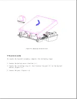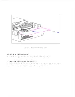
This section covers procedures for removing and replacing the battery pack
from the battery charger in the expansion base.
Refer to Appendix B for the following information:
o Increasing battery pack operating time
o Ensuring battery gauge accuracy
o Conditioning the battery pack
o Disposal of a used battery pack
>>>>>>>>>>>>>>>>>>>>>>>>>>>>>>>>> CAUTION <<<<<<<<<<<<<<<<<<<<<<<<<<<<<<<<<
Metal objects can damage the battery pack as well as the battery contacts
in the battery charging compartment. To prevent damage, do not let metal
objects touch any of the battery contacts.
Place only the Compaq LTE Elite
battery pack in the battery charging compartment. Do not attempt to insert
a battery pack for a Compaq LTE Lite Personal Computer or any other battery
packs.
The battery pack and the battery charging compartment are keyed to
allow only a correct insertion. Do not force the battery pack if insertion
does not occur easily.
Do not crush, puncture, incinerate or short external contacts on the
battery pack. Do not open a battery pack, as this damages the pack, makes
it unusable, and exposes potentially harmful battery components.
There are
no field-serviceable parts located inside the battery pack.
>>>>>>>>>>>>>>>>>>>>>>>>>>>>>>>>>>>>><<<<<<<<<<<<<<<<<<<<<<<<<<<<<<<<<<<<<<
Removing the Battery Pack
To remove a battery pack from the battery charging compartment, simply pull
it out.
Inserting the Battery Pack
To insert the battery pack in the battery charging compartment, complete
the following steps:
1. Insert the battery pack into the battery charging compartment with the
label on the battery pack facing up.
2. Push firmly on the battery pack to lock it into place.
NOTE: Whenever external electrical power is connected to the expansion
base, power is connected to the battery charging circuit, even when
the expansion base is turned off.
The battery charging LED turns on briefly when the battery is inserted. The
LED stays on, turns off, or flashes depending on the status of the battery
pack (Table 6.1).
9.6 Bottom Cover
To remove the bottom cover, complete the following steps:
Summary of Contents for LTE Elite
Page 140: ...7 Remove the hard drive security clips by gently lifting up on them Figure 4 32 ...
Page 248: ...4 Remove the keylock from the outside of the bottom cover Figure 9 5 ...
Page 249: ...5 Slide the plastic keylock barrel out of the bottom cover Figure 9 6 ...
Page 269: ...3 Disconnect the harness extension cable from the system board Figure 9 26 ...
Page 297: ...5 Slide the switch board out of the switch frame Figure 9 52 ...
Page 304: ...5 Replace the eject switch and screw Figure 9 59 ...
Page 309: ...5 Replace the power switch and screw Figure 9 64 ...
Page 348: ...7 Unlock the expansion base keylock Figure D 3 ...
Page 369: ...9 Push the lever toward the back of the convenience base Figure D 16 ...
Page 373: ...5 Slide the computer toward you to remove it from the convenience base ...
Page 387: ......

