


12. Insert the battery pack.
13. Turn on the computer to verify that the power-on password has been
cleared. If it has not been cleared, remove the battery pack and then
repeat steps 6 through 13. If the password is still not cleared,
replace the system board (Section 4.17).
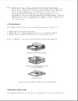
14. Replace the keyboard.
15. Replace the keyboard cover.
16. Reconnect the power cord to the external outlet.
17. Run Computer Setup (Section 1.8) to reconfigure the system and reset
the power-on and setup passwords.
2.2 Power-On Self-Test (POST)
The Power-On Self-Test (POST) is a series of diagnostic tests that run
automatically when the system is turned on. POST detects which types of
mass storage devices are installed in the computer and checks that the
following assemblies are functioning properly:
o Diskette drive
o Display
o External keyboard
o Hard drive
o Internal keyboard controller
o Memory expansion board
o Processor board
o Speaker on the power interface board (PIB)
o System board
o System memory
o Trackball assembly (POST identifies the trackball but does not actually
test it.)
o Video controller circuitry
Running POST
To run POST, complete the following steps:
1. Turn off the computer.
2. Turn on the computer.
Summary of Contents for LTE Elite
Page 140: ...7 Remove the hard drive security clips by gently lifting up on them Figure 4 32 ...
Page 248: ...4 Remove the keylock from the outside of the bottom cover Figure 9 5 ...
Page 249: ...5 Slide the plastic keylock barrel out of the bottom cover Figure 9 6 ...
Page 269: ...3 Disconnect the harness extension cable from the system board Figure 9 26 ...
Page 297: ...5 Slide the switch board out of the switch frame Figure 9 52 ...
Page 304: ...5 Replace the eject switch and screw Figure 9 59 ...
Page 309: ...5 Replace the power switch and screw Figure 9 64 ...
Page 348: ...7 Unlock the expansion base keylock Figure D 3 ...
Page 369: ...9 Push the lever toward the back of the convenience base Figure D 16 ...
Page 373: ...5 Slide the computer toward you to remove it from the convenience base ...
Page 387: ......


