


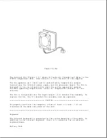


Keyboard/Mouse Connector
The keyboard/mouse connector can be connected to a PS/2 mouse or an external
enhanced keyboard. Connecting the mouse/keyboard connector to a mouse
disables the integrated trackball, while connecting the mouse/keyboard
connector to an external keyboard disables the internal keyboard.
Parallel Connector
The parallel connector supports the parallel interface which meets
EPP 1.9 specifications.
External Monitor Connector
The external monitor connector provides an output for an external monitor
with a maximum resolution of 1024 x 768 lines.
NOTE: The computer can simultaneously display on an external monitor and
the integrated display panel.
Numeric Keypad
Connecting the numeric keypad connector to an external numeric keypad
disables the embedded numeric keypad feature.
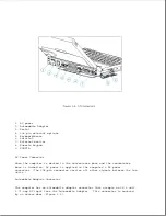
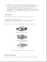
PCMCIA Connector
The computer has a PCMCIA connector accessible through a PCMCIA slot on the
left side of the computer (refer to "PCMCIA Slot" in Section 1.6). The
PCMCIA connector supports the PCMCIA interface which meets PCMCIA 2.1
specifications.
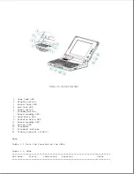
1.6 Functional Descriptions
This section covers functional descriptions of key parts and features of
the computer. For assembly/disassembly instructions for the parts described
in this section, refer to Chapter 4.
System Board
Summary of Contents for LTE Elite
Page 140: ...7 Remove the hard drive security clips by gently lifting up on them Figure 4 32 ...
Page 248: ...4 Remove the keylock from the outside of the bottom cover Figure 9 5 ...
Page 249: ...5 Slide the plastic keylock barrel out of the bottom cover Figure 9 6 ...
Page 269: ...3 Disconnect the harness extension cable from the system board Figure 9 26 ...
Page 297: ...5 Slide the switch board out of the switch frame Figure 9 52 ...
Page 304: ...5 Replace the eject switch and screw Figure 9 59 ...
Page 309: ...5 Replace the power switch and screw Figure 9 64 ...
Page 348: ...7 Unlock the expansion base keylock Figure D 3 ...
Page 369: ...9 Push the lever toward the back of the convenience base Figure D 16 ...
Page 373: ...5 Slide the computer toward you to remove it from the convenience base ...
Page 387: ......


