o Battery charging circuitry and battery contacts [10] for battery pack
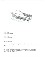
o External input/output (I/O) connectors (Figure 1-4)
o DC-to-DC power supply (refer to "DC-to-DC Power Supply" in this section)
o 256 Kbyte flashable shared system ROM and keyboard ROM
o 4 or 8 MB base RAM (depending on the model)
o System controller, which provides the following:
- Interface to the processor board for memory management (including
memory refresh)
- Two DMA controllers
- Two interrupt controllers
- Clock generator
- Programmable interval timer
- System management interrupt (SMI) support logic
- Power management features
o Peripheral controller, which provides the following:
- Integrated keyboard controller
- Industry Standard Architecture (ISA) support logic
- Circuit for interfacing to the hard drive
- Control of parallel and serial interfaces, including serial interfaces
for a numeric keypad, mouse/keyboard, and internal trackball
o PCMCIA controller
o Local bus video controller
o Diskette drive controller
o Docking sense logic
o Secondary temperature sensor for controlling the fan (refer to
"Temperature Sensors")
DC-to-DC Power Supply
The DC-to-DC power supply is integrated into the system board. It converts
DC voltage input to regulated 3.3 volts, 5 volts, and 12 volts DC. The DC
Summary of Contents for LTE Elite
Page 140: ...7 Remove the hard drive security clips by gently lifting up on them Figure 4 32 ...
Page 248: ...4 Remove the keylock from the outside of the bottom cover Figure 9 5 ...
Page 249: ...5 Slide the plastic keylock barrel out of the bottom cover Figure 9 6 ...
Page 269: ...3 Disconnect the harness extension cable from the system board Figure 9 26 ...
Page 297: ...5 Slide the switch board out of the switch frame Figure 9 52 ...
Page 304: ...5 Replace the eject switch and screw Figure 9 59 ...
Page 309: ...5 Replace the power switch and screw Figure 9 64 ...
Page 348: ...7 Unlock the expansion base keylock Figure D 3 ...
Page 369: ...9 Push the lever toward the back of the convenience base Figure D 16 ...
Page 373: ...5 Slide the computer toward you to remove it from the convenience base ...
Page 387: ......

