


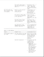


The expansion base and
The computer is not
Ensure that there is
computer do not power
completely docked in
no gap between the
on when either power
the expansion base.
expansion base and
switch is pressed, but
the rear of the
a beep is emitted from
computer. (Refer to
the expansion base and
Table 7-2 for more
there is some LED
information on
activity.
solving docking
problems.)
--------------------------------------------------
The computer is not
1. Remove the
powering on properly.
computer from the
expansion base and
attempt to power
it on by itself.
If the computer
does not power on
by itself, the
problem is with
the computer
(Table 2-26).
2. Try another
computer (if one
is available) in
the expansion base
to ensure that the
expansion base
powers up
properly.
--------------------------------------------------
The expansion base power
Replace the
supply is defective.
expansion base power
supply.
---------------------------------------------------------------------------
The expansion base
The internal devices have
Ensure that internal
does not turn on after
exceeded the maximum
devices do not exceed
an ISA expansion board
allocated power.
7A (35W) for the +5V
or an internal drive
output and 3A (36W)
is installed in the
for the +12V output.
expansion base.
===========================================================================
SCSI Problems
This section lists some common SCSI problems to check if the system cannot
communicate with a SCSI device.
When solving a SCSI problem, verify that:
o All SCSI devices are turned on before turning on the system.
o SCSI drivers are properly installed (Section F.6), the correct path is in
AUTOEXEC.BAT, and the drivers are loaded in CONFIG.SYS.
o The first device and the last device in the SCSI chain are properly
terminated (Sections F.1 and F.2).
o All SCSI devices have different SCSI IDs.
o The cables connecting the SCSI devices are properly seated.
Summary of Contents for LTE Elite
Page 140: ...7 Remove the hard drive security clips by gently lifting up on them Figure 4 32 ...
Page 248: ...4 Remove the keylock from the outside of the bottom cover Figure 9 5 ...
Page 249: ...5 Slide the plastic keylock barrel out of the bottom cover Figure 9 6 ...
Page 269: ...3 Disconnect the harness extension cable from the system board Figure 9 26 ...
Page 297: ...5 Slide the switch board out of the switch frame Figure 9 52 ...
Page 304: ...5 Replace the eject switch and screw Figure 9 59 ...
Page 309: ...5 Replace the power switch and screw Figure 9 64 ...
Page 348: ...7 Unlock the expansion base keylock Figure D 3 ...
Page 369: ...9 Push the lever toward the back of the convenience base Figure D 16 ...
Page 373: ...5 Slide the computer toward you to remove it from the convenience base ...
Page 387: ......


