


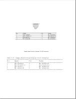

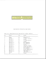


Table A-7. Compaq SmartStation 198-Pin External Options Connector
===========================================================================
Pin
Signal
Pin
Signal
===========================================================================
1
Printer Select
100
+5V Fused (computer)
2
Printer Busy
101
Printer Auto Line Feed *
3
Printer Data Bit 7
102
Printer Error *
4
Printer Data Bit 5
103
Ground
5
Ground
104
Printer Initialize *
6
Printer Data Bit 3
105
Diskette Write Gate *
7
Printer Data Bit 1
106
Diskette Read Data *
8
Printer Strobe *
107
Ground
9
+5V from Main Exp. Base
108
Power On *
10
Battery Voltage
109
Exp Device Connected *
11
Power Good Exp. Base
110
I/O Error Check *
12
Standby
111
Ground
13
Mouse Data
112
System Address Bit 4
14
Battery Voltage
113
System Address Bit 5
15
CRT-Red Analog
114
System Address Bit 6
16
CRT-Green Analog
115
Ground
17
CRT-Blue Analog
116
System Address Bit 7
18
CRT Horizontal Sync
117
System Address Bit 8
19
CRT Vertical Sync
118
System Address Bit 9
20
Ground
119
Ground
21
Serial-Data Term Ready
120
System Address Bit 10
22
Serial-Ring Indicator
121
System Address Bit 11
23
Serial Transmit Data
122
System Address Bit 12
24
Serial Clear-to-Send
123
System Address Bit 13
25
Ground
124
Ground
26
Serial Receive Data
125
System Address Bit 14
27
Serial Ready-to-Send
126
System Address Bit 15
28
Serial Carrier Detect
127
System Address Bit 16
29
Serial-Data Set Ready
128
Ground
30
Ground
129
System Address Bit 17
31
DMA Acknowledge 2 *
130
System Address Bit 18
32
DMA Acknowledge 1 *
131
System Address Bit 19
33
DMA Acknowledge 0 *
132
Ground
34
+5V Fused (computer)
133
Printer Select In *
35
Printer Paper Out
134
Diskette Boot
36
Printer Acknowledge *
135
Diskette Low Den. Media *
37
Printer Data Bit 6
136
Diskette Direction In *
38
Printer Data Bit 4
137
Ground
39
Ground
138
Diskette Index *
40
Printer Data Bit 2
139
Diskette Change *
41
Printer Data Bit 0
140
Diskette Head Select
42
Keypad Data
141
Ground
43
Battery Voltage
142
Reserved
44
Keyboard Clock
143
No Wait States *
45
Keyboard Data
144
Bus Ready
46
Mouse Clock
145
Ground
47
Battery Voltage
146
I/O Read Control *
48
Ground-CRT
147
I/O Write Control *
49
Ground-CRT
148
ISA Bus Clock
50
Ground-CRT
149
Ground
51
Ground-CRT
150
Address Latch Enable
52
Ground-CRT
151
DMA Cycle Indicator
53
DMA Request 1
152
Unlatched Address Bit 17
54
DMA Request 7
153
Ground
55
DMA Request 6
154
Unlatched Address Bit 18
Summary of Contents for LTE Elite
Page 140: ...7 Remove the hard drive security clips by gently lifting up on them Figure 4 32 ...
Page 248: ...4 Remove the keylock from the outside of the bottom cover Figure 9 5 ...
Page 249: ...5 Slide the plastic keylock barrel out of the bottom cover Figure 9 6 ...
Page 269: ...3 Disconnect the harness extension cable from the system board Figure 9 26 ...
Page 297: ...5 Slide the switch board out of the switch frame Figure 9 52 ...
Page 304: ...5 Replace the eject switch and screw Figure 9 59 ...
Page 309: ...5 Replace the power switch and screw Figure 9 64 ...
Page 348: ...7 Unlock the expansion base keylock Figure D 3 ...
Page 369: ...9 Push the lever toward the back of the convenience base Figure D 16 ...
Page 373: ...5 Slide the computer toward you to remove it from the convenience base ...
Page 387: ......


