DETAILED STEPS
Step 1
Attach an ESD-preventive wrist strap between you and an unpainted router surface.
Step 2
Locate the DIMM on the system board.
The DIMMs shown in xref Figure 14-12 and Figure 14-13 are representative and might not look exactly like
the DIMMs used on the RP; but the procedure is the same.
Note
Step 3
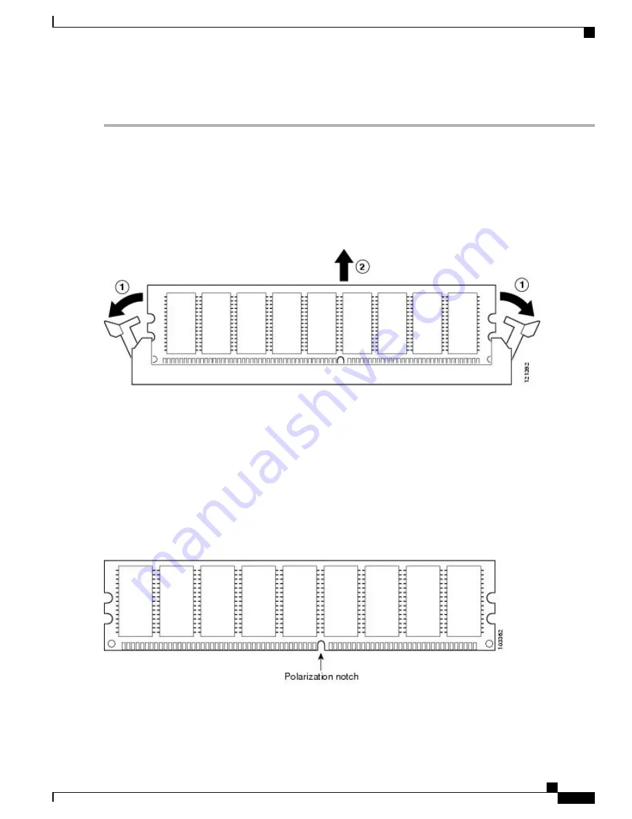
Press both spring latches outward to release the DIMM.
The following figure shows the Cisco ASR 1000 Series RP DIMM module spring latches.
Figure 238: Cisco ASR 1000 Series RP DIMM Module Spring Latches
insert callout table
1 - Pull spring clips outward.
2 - Pull DIMM out.
Step 4
Pull the latches away from the DIMM on both edges. This lifts the DIMM slightly. Gently lift the DIMM free from the
DIMM connector, taking care not to touch the pins that insert into the socket.
Step 5
Place the DIMM in an antistatic bag to protect the DIMM from ESD damage.
Forcing the DIMM into the socket can damage the DIMM. Use the notches on the DIMM to align the DIMM
in the DIMM socket before inserting it (see the following figure).
Caution
Figure 239: Cisco ASR 1000 Series RP DIMM Module Notch Location
Step 6
To install the DIMM memory card, locate the notches and align the DIMM with the socket before inserting it.
Cisco ASR 1000 Series Router Hardware Installation Guide
499
Removing and Replacing FRUs from the Cisco ASR 1000 Series Routers
Removing and Replacing the Cisco ASR1000-RP1 DIMM Memory Modules
Summary of Contents for ASR 1001
Page 2: ... 2013 2017 Cisco Systems Inc All rights reserved ...
Page 20: ...Cisco ASR 1000 Series Router Hardware Installation Guide xx Contents ...
Page 30: ...Cisco ASR 1000 Series Router Hardware Installation Guide xxx Preface Warning Definition ...
Page 32: ...Cisco ASR 1000 Series Router Hardware Installation Guide xxxii Preface Warning Definition ...


