background image

2-24          

Section 2: Electronics, Switches, Solenoids and Motors


Section Rev. December 2016

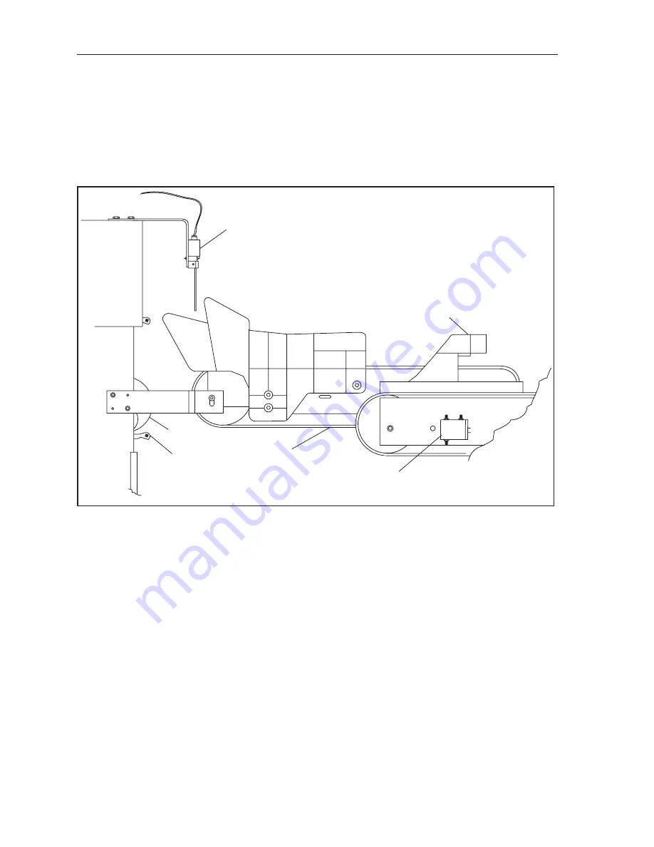
Shark Solenoid

This solenoid is used to control the Shark Fin guide.  Energizing the solenoid will cause the pin guide 

to flip left to direct the pin onto the right side of the distributor.  When the solenoid is de-energized, a 

return spring pulls the guide back to it original position deflecting pins to the left distributor lanes.  The 

pins are deflected in a (L-R-L-L-R, L-R-L-L-R) pattern.  The “R” designation is for the 10 pin or right 

hand side of the pinsetter.  The “L” designation is for the “7” pin or the left side of the pinsetter. The 

electronics determined when to energize the solenoid based on the signal coming from the pin count 

switch. 

(1)

PIN COUNT

SWITCH

(5)

PIN SHOVEL

(6)

PIN

(3)

SHARK

SOLENOID

(4)

GREEN

BELTS

(2)

SHARK FIN

GUIDE

Figure 2-21.  Shark Solenoid 

  (1)  PIN COUNT SWITCH 

(2)  SHARK FIN GUIDE 

(3)  SHARK SOLENOID

  (4)  GREEN BELTS 

(5)  PIN SHOVEL 

(6)  PIN

Summary of Contents for GS-X Series

Page 1: ...Operations Service Manual GS X Pinsetter with Advanced CE Guarding March 2017 47 902748 000...

Page 2: ...trademarks of Brunswick Bowling Products Manual Part No 47 902748 000 Notice If available updates to this manual can be found on line at www brunswickbowling com Confidential proprietary information A...

Page 3: ...r Power up Procedure Safety Controller 16 Pinsetter Restart Procedure Safety Controller 16 Pinsetter Status Light Machine Power on Sequence 17 Software Version 4 9 08 and prior 17 Software Version 4 9...

Page 4: ...2 Safety Section Section Rev February 2017 Intentionally Blank Page...

Page 5: ...ety Alerts alone cannot eliminate the hazards that they signal Strict compliance to these special instructions when performing the service plus training and Common Sense operation are major accident p...

Page 6: ...azards and or results of each method We have not attempted any such wide evaluation Therefore anyone who uses a service procedure and or tool which is not recommended by Brunswick must first completel...

Page 7: ...ing use and periodic technical inspections of the GS X Pinsetter Safety Controller system in particular Machine Directive 98 37 EEC Equipment Usage Directive 89 655 EEC the work safety regulations saf...

Page 8: ...the GS X Pinsetter Power Controller system are correctly instructed by specialist personnel before being allowed to operate the pinsetters Instructing the operating personnel is the responsibility of...

Page 9: ...rlock switch is closed rear door closed there is continuity from pin 1 to 2 and from pin 3 to 4 of the connector Then verify that when the interlock switch is opened rear door opened there is no conti...

Page 10: ...ive cleaning agents Static charges cause dust particles to be attracted to the lens You can prevent this effect by using the antistatic plastic cleaner SICK Part No 5 600 006 and the SICK lens cloth P...

Page 11: ...moving parts Remove rings watches earrings bracelets and other jewelry to avoid injury 9 Care should be taken while near the front of the machine Accidentally blocking the photocell beam will cause t...

Page 12: ...der the influence of alcohol drugs or any other substance that can impair your physical abilities or mental judgment 20 Always use the correct tools for the job 21 The GS Series pinsetter is designed...

Page 13: ...etters on a lane pair whenever an interlock is activated Refer to figure titled Advanced CE Guard Packages Advanced CE Guard Packages 1 SAFETY POWER CONTROLLER 2 MECHANIC S REMOTE DISPLAY 3 ELEVATOR G...

Page 14: ...front part of the pinsetter From the deployment position the platform can open to allow safe entry to the pindeck area of the machine An integrated ball stop prevent balls from entering the pinsetter...

Page 15: ...Section Rev February 2017 Safety Section 13 GS Safetty Mirror Safety Mirror...

Page 16: ...cess Hole Location to mount the optional Hold To Run Switch 2 Restart Switch Button used to restart the Safety Controller as indicated by the yellow restart LED after a power failure or interruption o...

Page 17: ...troller and the photo sensor receiver and transmitter 13 Controller The module that monitors the photo sensor receiver and transmitter and the interlock switches The display on the controller provides...

Page 18: ...POWER SWITCH ON GREEN LED ON PRESS PHOTO SENSOR RESTART BUTTON YELLOW LED ON PRESS RESTART BUTTON ON CONTROLLER RED LED ON REMOVE THE SOURCE OF THE SENSOR OBSTRUCTION PRESS PHOTO SENSOR RESTART BUTTON...

Page 19: ...fore servicing No light indicates the pinsetter may be READY TO RUN A signal from a remote location will cause the pinsetter to start WITHOUT WARNING Stay clear of machine Turn off the Stop Run switch...

Page 20: ...hown in the figure titled Pinsetter Access Points CAUTION Only use the access points as recommended With pinsetters equipped with Safety Controllers these access points are protected with interlock sw...

Page 21: ...all accelerator platform Area 3 Standing platforms between or at the front of the pinsetter Area 4 On the pindeck Area 5 On top of the distributor CAUTION When accessing the machine for work areas 3 5...

Page 22: ...rovide access to the ball accelerator elevator shark assembly ball cushion transport band and the back portion of the distributor allowing the mechanic to easily correct a machine stop or perform main...

Page 23: ...ned standing on the ladder or the platform on top of the ball accelerator s ball box Refer to the figure titled Pinsetter Work Area 2 Ball Accelerator Platform This area may be used for such activitie...

Page 24: ...Pinsetter Work Area 3 Standing Platforms This area may be used for such activities as 1 Cleaning distributor belts 2 Correcting pin handling issue at the front of the machine 3 Accessing the pinsetter...

Page 25: ...sing the underside of the distributor 4 Working on the setting table CAUTION Even though the pivoting walkway has an integrated ball stop which prevents a ball from entering the pinsetter always make...

Page 26: ...etter Work Area 5 Distributor This area may be used for such activities as 1 Replacing a division side table or sweep motor 2 Replacing the table or sweep drive assemblies 3 Replacing Pin Stations 4 R...

Page 27: ...work is to be performed turn off the main power switch on the Power Safety Controller and lock the switch in the off position using an approved lockout device to prohibit the machine from being turne...

Page 28: ...asking unit is lifted or the safety photo sensor in front of the machines is blocked or the rear access door is opened 2 Determine the reason for the stop Look for pins on shark switch assembly distri...

Page 29: ...ejector points Check for pins jammed at belt turning points Remove the jammed pins and place them on the outside return belt track 3 Check the pin ejector assemblies for proper positions 4 Continuous...

Page 30: ...has flipped over d Observe the elevator assembly for any other obstruction that may prohibit movement of the shovels 4 Remove the cause of the jam In the event of a flipped shovel manually rotate the...

Page 31: ...e locking mechanism 1 Turn the stop run on the mechanic s remote display or the Nexgen box to the stop position Turn off the main power switch on the Power Safety Controller box and lock the switch in...

Page 32: ...ball return rear door to gain access to the ball return area 5 Check for the cause of the ball return issue a Check for pins blocking the ball door opening b Check for pins inside the ball accelerator...

Page 33: ...ox to the stop position Turn off the main power switch on the Power Safety Controller box and lock the switch into the off position using an approved lockout device 2 Verify that all bowlers on the la...

Page 34: ...ne pair are off the approach and are not in a position to throw a ball 3 Remove guards as needed to gain access to the distributor area 4 From work area 1 2 or 3 clean all accessible distributor belts...

Page 35: ...ations 1 1 CONTENTS Section 1 Operations 3 Overview 3 Pinsetter Orientation 3 Pinsetter Description 4 Ball Pit 4 Ball Cushion 5 Transport Band 6 Ball Accelerator 7 Pin Elevator 9 Distributor 12 Settin...

Page 36: ...1 2 Section 1 Operations Section Rev February 2009 Intentionally Blank Page...

Page 37: ...nual This manual also provides troubleshooting guidelines that will help reduce downtime and can be used to provide years of reliable operation of your pinsetters PINSETTER ORIENTATION Whenever any po...

Page 38: ...ator Pin Elevator Distributor Setting Table Sweep Wagon Drive Frame Electronic Control Ball Pit The primary purpose of this area is to handle the initial impact of the pins and ball separate them from...

Page 39: ...of the machine while preventing them from returning forward where they may block the ball door Refer to Figure 1 2 Figure 1 2 Ball Cushion 1 RUBBER STOP 2 ADJUSTMENT BOLT 3 BALL CUSHION FRAME 4 SQUARE...

Page 40: ...ing rollers near the front of each side frame assist in keeping the belt on track To support the weight of the bowling ball s and pins two support boards are mounted between the side frames The front...

Page 41: ...d on two drums grips the ball and propels it forward to the ball lift Refer to Figure 1 4 Ball Accelerator Power to run the belt is furnished by a three phase motor incorporated into the rear drum 1 T...

Page 42: ...ted at the top of the door will hit the locking bolt To get the door to open the button at the top of the door must be pressed This causes the lever to lower so that it can pass under the locking bolt...

Page 43: ...or a shovel guide located on the right side of the elevator allows the front of the shovel to tip downward causing the pin to roll out of the shovel onto the shark assembly As the pin drops onto the s...

Page 44: ...2 PIN COUNT SWITCH 3 WEDGE GUIDE 4 SHOVEL GUIDE 5 CHAIN 6 1 OF 14 PIN SHOVELS 7 EJECTOR 8 RIGHT PIN DEFLECTOR 9 RIGHT PIN FEED DEFLECTOR 10 DAMPER PLATE 11 LOWER PAN GUIDE 12 LEFT PIN FEED DEFLECTOR...

Page 45: ...09 Section 1 Operations 1 11 Figure 1 7 Elevator Back View 1 STATUS LIGHT 2 EC SWITCH 3 SAFETY POWER CONTROLLER 4 MAIN POWER SWITCH 5 EMERGENCY STOP SWITCH 6 RESTART SWITCH 7 REMOTE DISPLAY 8 DOOR INT...

Page 46: ...feed lanes two cross over lanes 10 pin stations and right left overflow chutes See Figure 1 8 Figure 1 8 Distributor 1 TRANSPORT BAND DRIVE 2 PIN STATIONS 8 9 AND 10 3 CROSSOVER LANES PULLEY 4 FRONT D...

Page 47: ...voltage to the shark solenoid as needed so that the shark fin will force the pin to the right side of the distributor The pins will alternate between the left and the right side of the distributor in...

Page 48: ...l pins traveling along the distributor lane will pass by the occupied station Pins are held in the pin station until the pinholder located on the setting table is ready to receive them The pinholder s...

Page 49: ...e overflow chute located at the end of each outside distributor lane See Figure 1 11 Figure 1 11 Pin Overflow Area 1 OVERFLOW CHUTE 2 PIN IMPACT AREA BETWEEN 3 OVERFLOW SOCK REAR BOARD AND REAR ROLLER...

Page 50: ...must A Detect standing pins after a ball has been rolled Figure 1 12 B Pick up standing pins to allow the sweep to clear the dead wood Figure 1 13 C Receive pins from the distributor and set them on...

Page 51: ...Section Rev February 2009 Section 1 Operations 1 17 Figure 1 14 Setting New Pins...

Page 52: ...pins onto the lane surface Each pin holder has an single internal switch that serves two purposes 1 Detect standing pins so that the machine can determine what it needs to do and provide scoring if a...

Page 53: ...Normally the table will stop at pin detection height because a T stop screwed into the top of left hand table tube is caught by the stroke limiter plate prohibiting the table from lowering beyond the...

Page 54: ...to pivot out of the way of the T Stop so that the table can lower to the pin deck It also turns the left square shaft releasing the pinholder latch A large spring attached to the swing shafts pulls th...

Page 55: ...powering the spring causing the pin holders to rotate back to the horizontal position Refer to Figure 1 20 The latch will keep them in this position until the stroke limiter solenoid is energized agai...

Page 56: ...s right square shaft Refer to Figure 1 21 2 ST SWITCH 3 REAR SPOTTING TONG CLOSED 3 REAR SPOTTING TONG CLOSED 4 FRONT SPOTTING TONG GEAR RACK 5 SPOTTING TONG MAIN GEAR RACK 6 SQUARE SHAFT ATTACHMENT...

Page 57: ...tongs are closed their center pivot links lock the tongs in the closed position to prevent pins from dropping from the table when raised for clearing deadwood The square shaft turns in the opposite ro...

Page 58: ...y 2009 There are two types of spotting tongs Front facing Pin 1 4 5 and 6 Rear facing Pin 2 3 7 8 9 and 10 Figure 1 23 Spotting Tongs 1 CONNECTING LINKS IN LOCKED 2 SPOTTING TONGS CLOSED 3 DAMPER POSI...

Page 59: ...r 2 Sweep release assembly 3 Sweep attenuator shock assembly 4 Sweep wagon The sweep wagon is held up by the sweep release assembly To lower the sweep wagon the sweep release assembly s solenoid energ...

Page 60: ...RANK ARM 9 REARWARD POSITION 8 FORWARD POSITION 7 PUSHER ROD 6 VERTICAL GUIDE ROLLERS 10 HORIZONTAL GUIDE ROLLERS Figure 1 25 Sweep Motion 1 PIVOT POINT 2 SWEEP SHAFT 3 SWEEP CRANK ARM 4 G SWITCH 5 SW...

Page 61: ...on Refer to Figure 1 26 Figure 1 26 SM Switch Closed Sweep Forward 1 SM SWITCH 2 SWEEP SHAFT 3 CAM 4 SWEEP DRIVE SHAFT 5 RIGHT SIDE OF PINSETTER 6 TABLE CRANK ARM Near the end of the pinsetter cycle t...

Page 62: ...elease assembly can only come in contact with the roller when the table motor is turning clockwise Refer to Figures 1 27 and 1 28 3 TIPPER ROLLER 1 PIVOT BEARING 2 PIVOT LINK 4 TIPPER 5 TABLE SHAFT Fi...

Page 63: ...9 Section 1 Operations 1 29 1 TABLE SHAFT 2 PIVOT BEARING 3 PIVOT LINK 5 TIPPER ROLLER 6 TIPPER 4 PIVOT POINT Figure 1 28 Raising the Sweep CW 1 TABLE SHAFT 2 PIVOT BEARING 3 PIVOT LINK 4 PIVOT POINT...

Page 64: ...t move the pins through the machine This includes the distributor belts the shark assembly the elevator and the transport band The center motor is a 1 4 HP motor called the sweep motor Its function is...

Page 65: ...lic shock absorber a solenoid and a square shaft The plate and shock absorber slows the table as it lowers for a short stroke to detect or respot pins A solenoid pulls the stroke limiter plate out of...

Page 66: ...guide tower is bolted onto the pinsetter drive frame See Figure 1 32 At the top is a sprocket on which the table chain rides as the table is raised and lowered An out of range switch OOR is used to de...

Page 67: ...Remote Display Optional on pinsetters 8 Out Of Range Switch 9 Error Code OOR Switch 9 Pin Holder Switches 10 Error Codes Pin Loading and Detecting 10 ST Switch 11 Error Codes ST Switch 11 Sweep Motor...

Page 68: ...2 2 Section 2 Electronics Switches Solenoids and Motors Section Rev December 2016 Intentionally Blank Page...

Page 69: ...chine will shut off and display an error code describing the failure Figure 2 1 Switches Base and Fixed Guard Packages 1 NEXGEN ELECTRONICS 2 G SWITCH 3 ELEVATOR CONTROL SWITCH EC 4 PIN COUNT SWITCH 5...

Page 70: ...is in the standing pin detection position The C switch indicates that the drive chain and crank arm are fully extended and the table is fully down at the pin deck or completely resting on the stroke...

Page 71: ...lsed at least once every six seconds when the distributor motor is running the Pinsetter CPU determines that the elevator is either jammed a drive belt is slipping or some other defect or problem in t...

Page 72: ...fore the table can be lowered During operation the sweep release solenoid energizes upon ball detection If the G switch does not actuate within a few seconds after the solenoid energizes the pinsetter...

Page 73: ...ns 2 Reset This switch cycles the machine to the next ball 3 Stop Run This switch turns off the machine It must be in the stop position before entering the machine for service i NOTE When the pinsette...

Page 74: ...P RUN SWITCHES 3 RESET KEY 4 SET KEY 3 RESET KEY 4 SET KEY 7 LCD DISPLAY Scorer Scorer 0000000 0000000 Figure 2 6 Mechanic s Remote Display 1 Enter Key This push button key has two functions During pi...

Page 75: ...nge function can be disable through the scoring system For Brunswick Frameworx scorers when the lane is assigned to open play mode the scorer will not score and the pinsetter will respot the original...

Page 76: ...tches again If a pin is already loaded into the pin holder the detection of a standing pin will cause the switch to reopen When detecting a standing pin without a pin loaded into the pin holder the sw...

Page 77: ...activate close the switch when the spotting tongs are open This information used to determine if it is OK to lower the setting table at the start of a cycle Figure 2 9 ST Switch with Tongs Open 1 RIG...

Page 78: ...the way forward Activating this switch turns the sweep motor off allowing the motor s internal brake to stop the sweep The switch must be closed in order for the table motor to run 4 SWEEP DRIVE SHAF...

Page 79: ...will reverse the table for 1 5 seconds or until the C switch is closed An error code J1 or TS1 Jam will appear on the error display and the status light will flash The mechanic can then turn the stop...

Page 80: ...shaft to overpower a tension spring attached to the actuator lever Any time this switch is closed the table motor will reverse the table for 1 5 seconds or until the C switch is closed The machine wi...

Page 81: ...is sent to the pinsetter electronics where it is used to determine when to energize the shark solenoid 1 PIN COUNT SWITCH 5 PIN SHOVEL 6 PIN 3 SHARK SOLENOID 4 GREEN BELTS 2 SHARK FIN GUIDE Figure 2 1...

Page 82: ...setters on a lane pair by removing main power to the Nexgen box Once an emergency stop switch has been pressed the pinsetters cannot be restarted until the switch is returned to its closed position by...

Page 83: ...ergized for up to 90 seconds at a time if necessary i NOTE When working properly the black function solenoid coils will have 12 ohms of resistance while the red solenoid coils will have 26 ohms of res...

Page 84: ...hms BLACK 6 PIN HOLDER SOLENOID 26 ohms RED 5 SHARK SOLENOID 12 ohms BLACK 3 STROKE LIMITER SOLENOID 12 ohms BLACK 4 FRAME COUNTER Figure 2 15 Solenoids 1 SWEEP RELEASE SOLENOID 2 SPOTTING TONG SOLENO...

Page 85: ...revent the ball door from opening for a period of three or four seconds after ball detection Energizing the solenoid lowers the locking bolt so that it will block the door lever even if the ball door...

Page 86: ...tipper to pivot and the sweep wagon to drop from its up home position to the guarding position The solenoid is energized immediately when a ball passes through the ball detector s beam or someone pre...

Page 87: ...roke limiter plate and the table to lower fully to the pin deck It also turns the left hand square shaft releasing the pin holder s swing shaft latch to allow the pin holders to rotate vertical as the...

Page 88: ...ch assembly rotates a spindle shaft and through a helical gear drives the right hand square shaft When the main table drive shaft and right hand square shaft are turning counterclockwise the spotting...

Page 89: ...on its way up to the home position the grippers can open to load the pins When the table is down the grippers open to release a new set of pins onto the pin deck Figure 2 20 Pin Holder Horizontal Up f...

Page 90: ...ition deflecting pins to the left distributor lanes The pins are deflected in a L R L L R L R L L R pattern The R designation is for the 10 pin or right hand side of the pinsetter The L designation is...

Page 91: ...drives everything that moves pins around the machine including the round belts of the distributor the shovels in the elevator and the transport band in the pit area This motor typically runs for 45 se...

Page 92: ...off The brake holds the table up in the raised position Refer to Figure 2 22 WARNING Removing the setting table motor s V belt can cause the setting table to fall and crash to the pindeck possible cau...

Page 93: ...Closure Diagnostics Switch Diagnostics 25 Machine Cycle Diagnostics 25 Using the Diagnostics 26 Contact Closure Diagnostics Switch Diagnostics 26 Machine Cycle Diagnostics 27 Related Electronics 30 Ba...

Page 94: ...3 2 Section 3 Nexgen Electronics Section Rev February 2017 Intentionally Blank Page...

Page 95: ...ontroller Box Layout 1 INPUT OUTPUT PCB 2 NEXGEN CONTROLLER BOX 3 CPU PCB 4 HIGH VOLTAGE PCB 5 LEFT LANE ODD PINSETTER 6 RIGHT LANE EVEN PINSETTER The CPU Board gathers switch information and sends ou...

Page 96: ...T HAND GS X PINSETTER 3 TEL E FOUL 4 BALL DETECT 5 CENTRAL PROCESSING UNIT PCB 6 HIGH VOLTAGE PCB 7 SOLENOIDS 8 SWITCHES 9 MOTORS PINLIGHT 10 BALL ACCELERATOR 11 3 PHASE POWER 12 INPUT OUTPUT PCB 13 S...

Page 97: ...Controller receives incoming 3 phase power as well as the interlock signals and controls the 3 phase power to the Nexgen Because of this the main power switch emergency stop connectors and associated...

Page 98: ...per solenoids for the left pinsetter are energized via the voltages sent from this connector 7 P7 Pin Switches This connection provides input from the pin holder switches and spotting tong ST switch f...

Page 99: ...Section Rev February 2017 Section 3 Nexgen Electronics 3 7 Right Side Pinsetters with Advanced Guards Figure 3 4 Nexgen Controller Right Side View...

Page 100: ...r the even lane 7 P21 Rear Box Control This connection provides input from the even lane pinsetter s stop run switch located on the mechanic s remote display 8 P22 Masking Unit This connection provide...

Page 101: ...tage PCB depends on the operating voltage of the pinsetter Reference Figure 3 5 Table 1 Transformer Taps The BLK common wire will always connect to J37 of the High Voltage PCB Based on the Pinsetters...

Page 102: ...V BLK J37 BLK YEL J25 BLK RED J42 BLK WHT Not Used 200V BLK J37 BLK WHT J25 BLK YEL J42 BLK RED Not Used Table 1 Transformer Taps TRANSFORMER 2 INPUT VOLTAGE WIRE HIGH VOLTAGE PCB TERMINAL 220V 380V 4...

Page 103: ...box contains four circuit boards a CPU PCB a High Voltage PCB and two I O PCBs A power filter is also provided to condition the incoming 3 phase power Refer to Figure 3 6 Figure 3 6 Nexgen Controller...

Page 104: ...3 J5 J8 J4 J7 J9 JDPI JDP2 J10 1 A B C D TS2 SM IL OOR SWITCHES LEFT BALL DOOR SOLENOID TROUBLE LIGHT 2 BALL LIGHT 3 BALL DETECT FOUL BALL RACK RESET 4 SHARK SWITCH SWEEP STROKE SOLENOID AND TS1 6 SS...

Page 105: ...lows J1 J2 J3 F1 F2 F3 F5 F4 F6 F7 F9 F8 F10 J5 J9 J14 J4 J8 J13 J15 J12 J10 J11 1 LCD 2 KEYBOARD MEMBRANE 3 STOP RUN SWITCHES 4 MACHINE SWITCHES 4 MACHINE SWITCHES 15 DC POWER LED 15 DC POWER LED 15...

Page 106: ...ts This connection also provides input for the ball detectors J8 is for the left pinsetter and J9 is for the right pinsetter 7 Com A LED Labeled Com A this LED lights when communication to the Framewo...

Page 107: ...9 PINHOLDER SOLENOIDS STROKE LIMITER SOLENOID FRAME COUNTER 4 14 DC E F6 SHARK SOLENOID BALL DOOR SOLENOID 10 PINHOLDER SOLENOID 5 15 RIGHT PINSETTER DC F F1 1 2 3 PINHOLDER SOLENOIDS SPOTTING TONG SO...

Page 108: ...J21 J40 J30 J25 J41 J31 J42 J36 J39 F6 F5 J17 J5 J9 J11 J12 LS1 LS3 LS5 LS6 LS4 LS2 L1 L3 L5 L6 L4 L2 J14 J15 J16 F1 F2 F3 F4 1 MOTOR PINLIGHT CONTROL 2 LEFT HAND POWER RELAYS 6 PIN LIGHT FUSE 250V A...

Page 109: ...circuitry 4 Table Motor CW Fuse F1 F4 Fuses used to protect the table motor circuitry from excessive current when turning the table motor on in a clockwise rotation F1 is for the left pinsetter F4 is...

Page 110: ...to return to the mode selection menu 2 Enter Key The function of this key is dependent on what is being displayed on the LCD If the mode displayed on the LCD does not have a submenu this key allow th...

Page 111: ...this setting when a GS X is connected to an AS 80 or AS 90 scorer This selection does not have a submenu Diag This selection allows the mechanic to put the selected pinsetter into cycle diagnostics mo...

Page 112: ...g the second ball Y Double Detect Set if a scanner or CCD Camera are not used Frameworx scoring system default N Single Detect Set if a scanner CCD Camera or VPS are used or if no scoring system is us...

Page 113: ...version 4 08 02 and higher The selection determines whether the display will show error code using the standard 2 digit code or extended code Y Display error codes using extended format N Display err...

Page 114: ...l detection does not occur The selection is available on machines with software version 4 95 21 and higher 45 45 seconds default 50 50 seconds 55 55 seconds 60 60 seconds Shdw Bwl Time 0 1 2 3 This se...

Page 115: ...adjustment to the sweep board height will typically correct this NOTE 2 When the table continues past A the sweep will also lower This may result in insufficient clearance for some lane machines to p...

Page 116: ...e switches EC E G SM OOR ST Pincount Switch SS and displays the ones that are actuated on the left pinsetter EXT SW Left This selection checks the external inputs Ball Detect Foul Set And Reset and di...

Page 117: ...s the switches on the pinsetter and displays which switches are closed during the time the check is being made This mode can be used to verify that switches are working properly and the wiring between...

Page 118: ...he display options Pin SW Left Displays the pinholder switches that are actuated on the left pinsetter A indicates the switch is open Table SW Left Display switches A B C D TS1 and TS2 of the left pin...

Page 119: ...anel until the mode Diag appears on the display 3 Turn the stop run switch for the pinsetter is being tested to the run position 4 If a pinsetter stops during diagnostics and the status light is flash...

Page 120: ...Actuated Unactuated Unactuated Unactuated Sweep is up but not forward and the spotting Tongs are closed 94 Invld 4 Unactuated Unactuated Unactuated Unactuated Sweep is up but it is not forward and th...

Page 121: ...g Time Out Pin 10 75 G Ntfnd Switch G Expected But Not Found 50 Detect10 10 Pin Not Detected in Diagnostics 76 ST Ntfnd Switch ST Expected But Not Found 51 Detect1 1 Pin Not Detected in Diagnostics 90...

Page 122: ...m each other at 25 mm 1 above the capping Refer to Figures 3 11 and 3 12 The transmitter sends an infrared beam across the lane to the retroreflector which reflects the beam back to the receiver When...

Page 123: ...for a long enough duration Reset Button A bowler s reset button is located on the side of the ball rack This switch parallels the reset switch on the Nexgen Controller box and rear Control Box on the...

Page 124: ...15 VAC 6 Power Out to Nexgen Power conection for 3 phase power to the Nexgen box 7 Contactors Power contactors used to disconnect 3 phase power whenever the emergency off switch is pressed or an inter...

Page 125: ...Section Rev February 2017 Section 3 Nexgen Electronics 3 33 Safety Controller Codes Version I And II Table 5...

Page 126: ...r failure or interruption of power caused by opening the guard or masking unit interlock switch or photo sensors 3 Emergency Stop Switch Push this button to immediately remove power from the Nexgen bo...

Page 127: ...r receiver and transmitter 13 Controller The module that monitors the photo sensor receiver and transmitter and the interlock switches The display on the controller provides information as to the stat...

Page 128: ...r 8 Interlock or E Stop open 8 A 2 Sensor wiring Issue L 9 Supply voltage too low 1 Turn Control Power switch to ON 2 Check Safety Control power Press RESTART button 1 Check alignment of sensor receiv...

Page 129: ...HE MAIN POWER SWITCH ON GREEN LED ON PRESS PHOTO SENSOR RESTART BUTTON YELLOW LED ON PRESS RESTART BUTTON ON CONTROLLER RED LED ON REMOVE THE SOURCE OF THE SENSOR OBSTRUCTION PRESS PHOTO SENSOR RESTAR...

Page 130: ...ck for the bowler s use and on the rear control box located on the elevator for the mechanics use 4 Set Key These push button keys causes the last combination of pins to be set Push button switches wi...

Page 131: ...Section Rev February 2017 Section 3 Nexgen Electronics 3 39 Intentionally Blank...

Page 132: ...t assist in the operation of the pinsetters The cables are labeled for easy identification in the event the Nexgen box needs to be replaced However care must be exercised when making these changes as...

Page 133: ...N 68 100453 004 9 RIGHT HAND SIDE FUNCTION 10 MASKING UNIT ADAPTER 47 142674 000 OR 47 142730 000 47 142690 000 11 REAR CONTROL BOX 12 BALL DETECT FOUL BALL LIFT 13 LEFT HAND SIDE FUNCTION 47 245422 0...

Page 134: ...3 42 Section 3 Nexgen Electronics Section Rev February 2017 Intentionally Blank Page...

Page 135: ...0V 415V BLK BLK RED BLK WHT BLK YEL 208V 200V J37 J25 J42 BLK BLK YEL BLK RED BLK WHT J37 J25 BLK BLK RED BLK WHT BLK YEL J37 J25 J42 J42 TRANSFORMER 2 Input Voltage Wire High Voltage PCB Terminal 220...

Page 136: ...3 44 Section 3 Nexgen Electronics Section Rev February 2017 Back of 11 x 17 Here...

Page 137: ...EL 1 2 3 4 5 6 4 NC 4 NC 47 142616 000 External Distributor Motor Cable Assembly 1 TO DISTRIBUTOR 2 GROUND 3 TO P17 P20 ON NEXGEN BOX 4 NO CONNECTION V2 W1 U2 V1 W2 U1 2 GND 1 TO SWEEP MOTOR P16 P19 G...

Page 138: ...2 TO SWEEP RELEASE 3 TO SPOTTING TONG SOLENOID CONTROLLER SOLENOID 4 TO STROKE LIMITER 5 TS1 SWITCH 6 G SWITCH SOLENOID 7 EC SWITCH 8 PIN COUNT SWITCH 9 SHARK SOLENOID 10 NO CONNECTION 2 2 2 2 2 2 2...

Page 139: ...TO P2 OR P22 NEXGEN BOX 2 MASKING UNIT CABLE 3 NO CONNECTION 47 142730 000 Right Side Function Cable Assembly Revision B 1 TO P1 P3 NEXGEN BOX 2 SM SWITCH 3 A SWITCH 4 B SWITCH 5 C SWITCH 6 D SWITCH...

Page 140: ...TCH 9 TROUBLE LIGHT 10 BALL DOOR SOLENOID 11 NO CONNECTION 12 AS 13 INTERLOCK JUMPER 1 ENTER KEY 2 MODE KEY STOP RUN RUN STOP 7 UP DOWN ARROW KEYS 5 STOP RUN SWITCHES 5 STOP RUN SWITCHES 3 RESET KEY 4...

Page 141: ...Y BOX 2 GROUND 3 P19 PIN 2C P19 PIN 16 4 TO NEXGEN P21 5 TO NEXGEN P3 47 142762 000 GS X Rear Display Power Stop Switches 1 LAN A 2 LAN B 3 GROUND 4 CHASSIS GROUND 5 DRAIN 6 NO CONNECTION 7 SHELL 8 GS...

Page 142: ...WITCH 8 PIN COUNT SWITCH 9 SHARK SOLENOID 10 NO CONNECTION 47 142861 000 Masking Unit Interlock Cable Assembly 1 TO INTERLOCK ON SAFETY 2 TO 12 ON INTERLOCK SWITCH CONTROL BOX TO 11 ON INTERLOCK SWITC...

Page 143: ...gen Electronics 3 51 47 142863 000 Photosensor Receiver cable Assembly 1 TO RECEIVER INPUT ON SAFEETY CONTROLLER BOX 2 NO CONNECTION 47 142864 000 Photosensor Send Cable Assembly 1 TO RECEIVER INPUT O...

Page 144: ...3 52 Section 3 Nexgen Electronics Section Rev February 2017 47 142834 000 CE Safety Power Controller 1 INTERLOCK 2 RECEIVE 3 SEND...

Page 145: ...Y GRN 16 PIN SOL 1 17 PIN 2 18 PIN 3 19 PIN 4 20 PIN 5 21 PIN 6 22 PIN 7 23 PIN 8 24 PIN 9 25 PIN 10 SOL SOL SOL SOL SOL SOL SOL SOL SOL A B C OS SW ST D 47 245421 004 External Setting Table Cable Ass...

Page 146: ...1 1 8 WIRING TERMINAL BLOCK 9 11 WIRES RED COMMON FOR ALL PINHOLDER SWITCHES 10 4 WIRES BLUE COMMON SOLENOID 1 2 3 11 4 WIRES BLUE COMMON SOLENOID 4 5 6 12 4 WIRES BLUE COMMON SOLENOID 7 8 9 7 8 9 10...

Page 147: ...Section Rev February 2017 Section 3 Nexgen Electronics 3 55 47 142880 000 Rear Gate Interlock Cable 47 142881 000 Masking Unit Interlock Cable 47 142865 000 Photosensor Send Cable...

Page 148: ...xgen Electronics Section Rev February 2017 47 142874 000 Photosensor Receive Cable 47 142875 000 Photosensor Adapter Cable for Walkway with Obstruction 47 142878 000 Interlock Y Cable for Odd and Sepa...

Page 149: ...s 3 57 1 2 5 4 3 7 6 1 TERMINAL BOX BLK WHT RED YEL GRN YEL PH1 PH2 PH3 N GND P14 1 5 6 7 4 AC Power Input 380V x 400V 1 TERMINAL BOX 1 TERMINAL BOX BLK WHT RED YEL GRN YEL PH1 PH2 PH3 GND P14 1 5 6 7...

Page 150: ...3 58 Section 3 Nexgen Electronics Section Rev February 2017 Intentionally Blank Page...

Page 151: ...n 4 Pinsetter Cycles 3 General Information 3 Cycles 7 First Ball Strike Cycle 9 First Ball Standing Pins Cycle 11 First Ball Short Cycle 13 First Ball Out of Range 15 First Ball Foul 17 Second Ball Si...

Page 152: ...4 2 Section 4 Pinsetter Cycles Section Rev February 2009 Intentionally Blank Page...

Page 153: ...on During the sweep segment deadwood is cleared from the pin deck and flat gutters Refer to Figure 4 3 The final segment is the preparation stroke in which the pinsetter readies itself for the next ba...

Page 154: ...4 4 Section 4 Pinsetter Cycles Section Rev February 2009 Figure 4 2 Detection Stroke 1 SWITCH C 2 SWITCH B 3 CAM ROTATING COUNTER CLOCKWISE 4 SWITCH A 5 SWITCH D 6 MOVEMENT OF TABLE 7 COUNTERCLOCKWISE...

Page 155: ...Section Rev February 2009 Section 4 Pinsetter Cycles 4 5 Figure 4 3 Sweeping Deadwood 1 SWITCH C 2 SWITCH B 3 CAM STOPPED 4 SWITCH A 5 SWITCH D...

Page 156: ...etter Cycles Section Rev February 2009 Figure 4 4 Preparation 1 SWITCH C 2 SWITCH B 3 CAM ROTATING CLOCKWISE 4 SWITCH A 5 SWITCH D 6 SHORT STROKE 7 CLOCKWISE 8 LONG STROKE 9 SWITCH CLUSTER ROTATION 10...

Page 157: ...ollowing conditions must be met a Table is up A switch is closed b Sweep is forward SM switch is closed c Sweep is up G switch is not closed d Spotting tongs are fully open ST switch is closed To begi...

Page 158: ...4 8 Section 4 Pinsetter Cycles Section Rev February 2009 Figure 4 5 Pinsetter Cycles...

Page 159: ...5 READY FOR FIRST BALL 6 LOAD 7 AND 10 PIN IF AVAILABLE 21 CW 2 CCW C C D B B D 22 DETECTION HEIGHT ST ST 23 SPOTTING TONG SWITCH Figure 4 6 First Ball Strike Cycle 1 TABLE HOME UP 2 COUNTERCLOCKWISE...

Page 160: ...on pulling the sweep back then forward to clear the deadwood When the sweep wagon is fully forward once again switch SM closes causing sweep motor to turn off 11 The table motor runs clockwise and the...

Page 161: ...P E N I N G T O N G S O P E N G R I P P E R S 7 S P O T T I N G T O N G S O L E N O I D E N E R G I Z E S R E O P E N I N G T O N G S A A G SM ST ST SM A A SM G SM C C B D D B 22 DETECTION HEIGHT Figu...

Page 162: ...motor turns off when switch A is closed 10 The sweep motor turns on pulling the sweep back then forward to clear the deadwood When the sweep wagon is fully forward once again the SM switch closes caus...

Page 163: ...USE OF A 7 PIN DOWN ONLY B 10 PIN DOWN ONLY C GUTTER BALL NO SWEEP NECESSARY 1 0 R E A D P I N H O L D E R S 9 S T O P R E V E R S E T A B L E M O T O R 8 O P E N G R I P P E R S A 13 SWITCH CLUSTER 1...

Page 164: ...indicating the table entered the detection area 5 The table will make a short stroke as it stops on the stroke limiter plate 6 At the B switch the Pinsetter CPU will read the pin holder switches and f...

Page 165: ...ian to remove any deadwood and to restart the pinsetter Refer to Figure 4 9 The cycle occurs as follows 1 TABLE HOME UP 8 P I N S E T T E R S T O P R E D T R O U B L E L I G H T E R R O R C O D E P O...

Page 166: ...continues to turn the cam past switches C and D switches until switch A is closed 7 The pinsetter will shut off at A switch with the sweep still down in the guarding position The trouble light will fl...

Page 167: ...E R S 1 5 F O U L D E T E C T O R I G N O R E P I N H O L D E R S 9 NEW PINSETTING STROKE A A A A B C D D C B G G SM SM SM SM 21 DETECTION HEIGHT ST ST 22 SPOTTING TONGS OPEN Figure 4 10 First Ball F...

Page 168: ...ipper at switch A the table motor shuts off 11 The sweep motor turns on pulling the sweep back then forward to clear the pin deck When the sweep wagon is fully forward once again switch SM closes caus...

Page 169: ...E 17 DETECTION HEIGHT ST ST Figure 4 11 Second Ball Single Detect Cycle 1 TABLE HOME UP 2 LOADING PINS 3 CLOCKWISE 4 STROKE LIMITER SOLENOID 5 READY FOR FIRST BALL 6 LOAD 7 AND 10 PIN IF AVAILABLE ENE...

Page 170: ...to go down to the pin deck and releases the swing shafts on the table allowing the pin holders to go into the vertical pinsetting position 6 The cam passes switch D and at switch C the pin holder sole...

Page 171: ...BLE 4 CW 2 CCW 21 DETECTION HEIGHT ST ST ST ST Figure 4 12 Second Ball Double Detect Cycle 1 TABLE HOME UP 2 COUNTERCLOCKWISE 3 LOAD PINS IN TABLE 4 CLOCKWISE 5 STROKE LIMITER SOLENOID 6 RAISE SWEEP E...

Page 172: ...e sweep wagon is fully forward once again switch SM closes causing sweep motor to turn off 11 The table motor runs clockwise and the cam leaves switch A and travels to switch D 12 As the table starts...

Page 173: ...STROKE 11 RAISE SWEEP 12 SWEEP 13 NEW PINSETTING STROKE 14 READY FOR FIRST BALL 15 LOAD 7 AND 10 PIN IF AVAILABLE 16 OPEN 7 AND 10 PIN GRIPPERS 17 CLOSE GRIPPERS 18 OPEN GRIPPERS SET NEW PINS 19 OPEN...

Page 174: ...PU immediately energizes the sweep release solenoid to drop the sweep wagon into the guarding position again actuating switch G 12 Motor turns counterclockwise rotating the switch cam from A to B to C...

Page 175: ...tion Adjustment 21 Pin Overflow Socks 22 Setting Table Levelness Adjustment 23 Switch Cluster Cam Timing 25 Table Height Adjustment 27 Raised Position Measurement 27 Lower Position Measurement 28 Posi...

Page 176: ...5 2 Section 5 Adjustments Section Rev February 2017 Intentionally Blank Page...

Page 177: ...mbly contains three screws that are used to align the units infra red beam with a reflector opposite side of the lane Refer to Figure 5 1 1 BALL DETECT 2 REFLECTOR 3 DIVISION KICKBACK 4 BALL RETURN KI...

Page 178: ...nd after adjusting 2 Cover the reflector with a dark non reflective object The red LED should be lit indicating the beam is not being received 3 Hold an unmounted reflector in your hand and move it ab...

Page 179: ...below is a starting point that will change slightly when adjusting the transport band to track and center properly CAUTION Before making the tension adjustment verify that the hardware mounting the t...

Page 180: ...1 2 turn 1 THREADED BOLT FOR TENSIONING 2 BEARING JAM NUT 3 INSIDE JAM NUT 4 OUTSIDE JAM NUT Figure 5 4 Jam Nut for Tensioning the Transport Band 1 THREADED BOLT FOR 2 BEARING JAM NUT 3 INSIDE JAM NU...

Page 181: ...justment 1 TRANSPORT BAND DRIVE 2 V BELT 3 TENSION ADJUSTING SCREW ASSEMBLY 4 ROUND BELT 5 SET SCREW 3 Check the green belt and V belt to make sure they are seated properly in their pulleys 4 Hand tig...

Page 182: ...l door opening The cushion must also be adjusted so that it does not run on the kick backs Front Position 1 Using the adjusting bolt shown in Figure 5 6 adjust the ball cushion so the front of the cus...

Page 183: ...te To adjust loosen the set screws on the stop collars reposition the cushion frame and retighten the set screws Refer to Figures 5 8 and 5 9 Figure 5 8 Adjust Cushion Frame Sideways 1 SET SCREW 2 BAL...

Page 184: ...STOP BRACKET 2 Verify that lower locknut and special round nut on shock absorber bracket Figure 5 11 are installed properly No threads must be visible below bottom locknut 2 1 mm GAP 4 LOCKNUT 3 SPECI...

Page 185: ...ttom of the ball door Refer to Figure 5 12 6 BALL DOOR 8 SUPPORT BOARD 1 BALL DOOR PROTECTOR RING 6 BALL DOOR 7 STOP COLLAR WILL ADJUST VERTICAL PLACEMENT ONLY 2 PLASTIC FRAMING 2 PLASTIC FRAMING 3 SH...

Page 186: ...DOOR KEY 5 HEX HEAD SCREWS 6 BALL DOOR SOLENOID 7 LOCKING BOLT 1 Loosening the two bolts that mount the locking bolt solenoid assembly to the accelerator frame Lower the locking bolt assembly 2 Place...

Page 187: ...tely 185 mm from spring hook to spring hook Refer to Figure 5 14 Adjust by tightening or loosening the two tensioning nuts that secure the long tension bar to the rear of the accelerator frame Adjust...

Page 188: ...t is not centered on the front pulley drum a Using a 17 mm socket ratchet and wrench loosen the two screws and nuts securing the pivot levers ONLY loosen screws enough to allow slight adjustment of pi...

Page 189: ...edged under the deflector and the outside edge of the deflectors firmly touch the kickback or ball accelerator Start with a 6 mm 1 5 mm gap between the transport band and bottom of the deflectors and...

Page 190: ...edges Refer to Figure 5 17 7 SHOVEL CAM 3 LOWER SHOVEL END 2 CENTER LINE ON SHOVEL CAM 4 PIN TURN WEDGE 5 WOOD TEMPLATE 22 mm 2 mm 1 ATTACHING HARDWARE 6 PIN SHOVEL GUIDE ROLLER Figure 5 17 Elevator P...

Page 191: ...er to Figure 5 18 Figure 5 18 Tension Adjustment 1 ELEVATOR DRIVE PULLEY 2 TENSION ADJUSTING SCREW 3 GREEN BELT 4 V BELT 3 Check the green belt and V belt to make sure they are seated properly in thei...

Page 192: ...ossible i NOTE Prior to making this adjustment make sure the shark assembly is level and positioned 135 mm from the back plate of the elevator Loosen the switch actuator clamp and set the switch actua...

Page 193: ...of movement by manually moving the belt forward and backward Refer to Figure 5 20 This will allow for the proper placement of the pins into the shark assembly Figure 5 20 Pin Turn Wedge Positioning 1...

Page 194: ...gure 5 21 and Figure 5 22 to properly position the level and Figure 5 20 for the adjustment location 3 SHARK FIN 4 ROUND BELTS 2 LEVEL 1 PIN GUIDE WEDGES Figure 5 21 Shark Switch Leveling Adjustment S...

Page 195: ...h A actuated measure the clearance between the bottom leg of the pin release lever and the closed gripper A clearance of 7 mm 2 mm should be visible between each pin release lever and the closed pinho...

Page 196: ...insure sufficient clamping strength when mounting the sock onto the overflow chute The overflow socks must face each other so the pin lands on the transport band between the rear transport band rolle...

Page 197: ...he front back and side to side position of the table tube using a level Refer to Figure 5 26 If adjustment is needed loosen the 24 mm hex nuts on the setting table studs Refer to Figure 5 27 Adjust th...

Page 198: ...e dimension at these three points must be within 3 mm of each other CAUTION Do not lean on the table while checking these measurements 5 To adjust lower or raise the large hex nuts 24 mm socket and dr...

Page 199: ...e table motor is operated clockwise or counterclockwise Improper timing can cause scoring problems hinder the machines ability to pick up or spot pins and in some cases cause the table and sweep to co...

Page 200: ...CH A 7 ALIGN PEAK OF SWITCH ARM 3 To verify the timing is correct compare the distance the drive chain is offset from the center line of the crank arm when the table motor turns off at the A switch af...

Page 201: ...e may be achieved by removing the pivot bearing from the crank arm shaft flipping it over and reinstalling it The table height must be measured at two places to determine if adjustment is required Fir...

Page 202: ...ET 2 TS 2 SWITCH 3 OOR SWITCH 4 CHAIN LENGTH PIVOT BEARING 5 TABLE SHAFT 6 CRANK ARM 7 CRANK ARM ADJUSTMENT 8 TABLE LIFT CHAIN 9 282 mm DEFAULT SCREWS 10 HOLE 3 DEFAULT The proper height for the table...

Page 203: ...gure 5 36 to adjust the table height to the required position i NOTE If both the crank and the chain are being adjusted they should each be moved equally one half the total distance desired Example 1...

Page 204: ...ring 1 HOLE 1 2 HOLE 2 3 HOLE 3 FACTORY DEFAULT 4 HOLE 4 5 HOLE 5 6 HOLE 6 7 HOLE 7 8 FRONT VIEW 9 BACK VIEW Figure 5 35 Pivot Bearing Dimensions NOTE L Lengthen S Shorten NC No Change All numbers are...

Page 205: ...Section Rev February 2017 Section 5 Adjustments 5 31 Figure 5 36 Check Pivot Bearing Clearance 1 VERIFY CLEARANCE 2 MAIN SWEEP ARM 3 PIVOT BEARING 4 CRANK ARM...

Page 206: ...oo 1 Weight of pin will not allow grippers to open to Far From Pin Deck release pins to the lane Distributor Position Table Too Far 1 Pin grippers may not make proper contact with the From Distributor...

Page 207: ...in relation to their pin spots Determine which pins are off spot and adjust as follows Figure 5 37 Proper Pin Position 1 FRONT OF PIN 2 PIN SPOT 3 PIN DECK Side to Side 1 To adjust individual pins lef...

Page 208: ...the jam nut on the vertical stop bolt mounted on the rear right swing shaft Refer to Figure 5 39 This bolt stops the vertical rotation of the rear pin holder swing shaft when the table goes down for...

Page 209: ...5 40 Swing Arm Adjustment 1 SWING ARM INTERLINK BOLT 2 SWING ARM 3 GAP WILL INCREASE OR DECREASE AS CAM IS RAISED OR LOWERED WITH SCREWDRIVER 4 CAM 3 Move the interlink bolt and cam up or down as desi...

Page 210: ...ed by the stroke limiter Before making any adjustment verify that the stroke limiter shock absorber is in good shape and the table is level 1 Set 10 pins on spot on the lane surface 2 Lower the settin...

Page 211: ...the stroke limiter mounting bracket s vertical bolt and loosen the two mounting bolts illustrated in Figure 5 42 Lower or raise the stroke limiter as needed Repeat steps 1 4 until the 3 5 mm clearance...

Page 212: ...ed in the solenoid Reposition the solenoid to achieve a 5 mm clearance Retighten the mounting screws Figure 5 43 Stroke Limiter Clearance 1 STROKE LIMITER PLATE Figure 5 44 Stroke Limiter Adjustment 1...

Page 213: ...quickly should there be a problem with the holders returning horizontal When the table is at home position A Switch the arm should push upward approximately 20 mm and be located squarely on the table...

Page 214: ...els far enough horizontally so that the latch can catch the latch bow and will move freely when the stroke limiter solenoid is energized 1 Raise the setting table to its highest position 2 Check for a...

Page 215: ...of the tongs causing the spotting tong clutch to slip The clutch has 3 tension setting to provide compesate for clutch wear and ensure proper torque on the drive shaft The normal position for the tens...

Page 216: ...the horizontal guide rollers and position the sweep side to side Refer to Figure 5 51 i NOTE Check the sweep wagon in the forward and rearward position for clearance Figure 5 50 Sweep Attenuator Swit...

Page 217: ...rs have a minimum clearance of 5 mm from the inside wall of the side frame and each vertical roller is fully resting on the rails To adjust loosen the mounting hardware for the horizontal guide roller...

Page 218: ...rd has sufficient clearance from the pinsetter frame when it is in it up position A 50 mm 1 mm distance is recommended Refer to Figures 5 52 and 5 53 CAUTION After changing the chain position on the p...

Page 219: ...n NC No Change All numbers are in millimeters Example Moving from hole 1 to hole 2 S2 Shortens the chain 2 mm 1 PIVOT BEARING 2 SETTING TABLE GEAR 3 SWEEP RELEASE CHAIN 4 VERIFY CLEARANCE Figure 5 54...

Page 220: ...UTTER THESE SCREWS 4 GUTTER ADAPTER DISTRIBUTOR DRIVE BELT ADJUSTMENT The two distributor V belts may need occasional adjustment When replacing these V belts they should be done in pairs with both bel...

Page 221: ...e bearing plate to the left drive frame Move the plate using the chain tiension adjuster until the desired amount of free play is obtained Retighten mounting bolts Refer to Figure 5 57 CAUTION If the...

Page 222: ...need occasional adjustment to remove excessive free play due to the chain stretching To adjust loosen the two bolts on both tensioning plates on the sides of the elevator and the jam nut on the tensio...

Page 223: ...When adjusting for proper tooth gap it is important to check the entire travel area It is possible to have a gear rack properly adjusted in one area and be too loose or too tight in another area of tr...

Page 224: ...s the Spotting Tong switch illustrated in Figure 5 63 are to be adjusted as shown in View A Views B and C illustrate being adjusted too far away and too close for proper operation 1 CORRECT VIEW A 4 S...

Page 225: ...009 Section 6 Troubleshooting 6 1 CONTENTS Section 6 Troubleshooting 3 Bowling in Progress 3 Pinsetter Clearing Procedure After Stop 3 Cable Repair 7 Error Codes Description and Causes 8 Problem Cause...

Page 226: ...6 2 Section 6 Troubleshooting Section Rev February 2009 Intentionally Blank Page...

Page 227: ...ter may not be detected by the Pinsetter CPU Examples are ball accelerator problems or scoring errors In these situations the status light will not flash to indicate a problem The following procedure...

Page 228: ...ition Figure 6 1 Top of Nexgen Controller Mechanic s Remote Display 1 DIAGNOSTIC DISPLAY Table 6 1 lists the error codes that may be displayed when the Pinsetter CPU has detected a problem with the pi...

Page 229: ...n 10 76 STNNftnd Switch STN Expected But Not Found 50 Detect10 10 Pin Not Detected in Diagnostics 90 Invld 0 Invalid Machine State 0 51 Detect1 1 Pin Not Detected in Diagnostics 91 Invld 1 Invalid Mac...

Page 230: ...not forward the Table is not at home position and the Spotting Tongs are closed 95 Invld 5 Un Actuated Actuated Un Actuated Un Actuated Sweep is not forward the Table is not at home position and the...

Page 231: ...able carefully inspect connections on each end of the cable for damage such as bent or broken pins or loose crimped connections and hold down springs Ribbon cables generally cannot be repaired and mus...

Page 232: ...owering properly Check for binds in the table racks or the chain lowering mechanism 01 02 03 04 05 06 07 08 09 10 Pin1 Ld Pin2 Ld Pin3 Ld Pin4 Ld Pin5 Ld Pin6 Ld Pin7 Ld Pin8 Ld Pin9 Ld Pin10 Ld PIN L...

Page 233: ...onnection on the H V PCB or Bad H V PCB Nexgen Faulty A Switch 61 B Found SWITCH B NOT EXPECTED BUT FOUND This switch was actuated at the wrong time or continuously 1 2 Switch B on the switch cluster...

Page 234: ...ng solenoid not energizing Check fuses on Nexgen CPU PCB Spotting tong clutch slipping Clean reset tension and readjust One or more set of spotting tongs damaged or binding Drive gears on the square s...

Page 235: ...M Ntfnd SWITCH SM EXPECTED BUT NOT FOUND This error indicates that the sweep is not forward or is unable to stop at the forward position 1 2 3 4 Sweep motor brake not preventing the motor from coastin...

Page 236: ...3 4 5 Elevator pin shovel flipped and wedged in the elevator Pin caught in the elevator preventing rotation of the shovels Transport drive has a bind which prevents the rear distributor shaft from rot...

Page 237: ...ll off transition track 1 2 3 4 5 6 7 8 9 Remove pins Adjust transport band Adjust or lubricate ball door Adjust ball cushion Replace or weld belt See Servicing section Replace transport band Replace...

Page 238: ...adjust switch Turn on all switches Check plugs and connectors Reset breakers Have line voltage corrected Set machine to proper mode 4 Pinsetter cycles independently One cycle only CAUTION Camera flas...

Page 239: ...ne cause of trouble repair and restart machine Turn on switch Relplace Nexgen H V PCB 6b Individual motor does not operate 1 2 3 4 Main house breaker box or faulty power supply connections Faulty cabl...

Page 240: ...ot level on distributor or riding in top of belt rail 1 2 3 4 5 6 Clean with all purpose cleaner Remove section of belt and weld back together lubricate belt Replace or weld belt Replace as required A...

Page 241: ...ly 1 2 3 Faulty switch A or cam misadjusted Missing screw on switch actuator Faulty Nexgen CPU or H V PCB 1 2 3 Adjust or replace actuator Replace screw or switch actuator cam as required Replace faul...

Page 242: ...pin holder solenoid s or cable harness s Faulty stroke limiter solenoid 1 2 3 4 Replace switch or switch finger Determine cause and adjust as required Replace solenoid s Check harness cable and connec...

Page 243: ...Repair connections Change the Nexgen CPU PCB Repair pin holder switch or switch actuator 22 Table is full but does not lower 1 2 3 4 5 6 Faulty pinholder microswitches CPU fuse Is blown Nexgen Faulty...

Page 244: ...itch or out of range switch Spotting tongs are obstructed Faulty Nexgen CPU Stroke limiter Assembly set too high score strike 1 2 3 4 5 6 7 Remove all lubricants and dirt from clutch face Adjust tensi...

Page 245: ...tment not correct Faulty motor rotation Main power supply on too low a voltage Faulty switch cluster cable trouble light and ball door cable Faulty ball lift cable foul optical trigger cable After abo...

Page 246: ...6 22 Section 6 Troubleshooting Section Rev February 2009 Intentionally Blank...

Page 247: ...istration and Organization 9 Main Frame Assembly 10 Distributor Assembly 10 Detailed Maintenance Schedule 12 Variable Schedule Items 12 Fixed Schedule Items 12 Daily Maintenance 12 Weekly Maintenance...

Page 248: ...eep Wagon Roller Shafts 26 Stroke Limiter Shock Absorber 27 Sweep Release Pivot Bearing 27 Shark Switch Gears 28 Semi Annual 28 Motor Mounting Brackets Shafts 28 Pin Station Assembly 29 Transport Band...

Page 249: ...nce can save time and effort In general preventative maintenance requires the following 1 Inspection and correcting any problem found The pinsetter should be inspected periodically for the following c...

Page 250: ...s a good practice to wipe off the old grease and dirt it has collected with it BEFORE applying a new coat of grease Do not over grease the part as the grease can get into areas that can cause problems...

Page 251: ...condition and adjustment Check all pin shovels and shovel hardware Inspect all shovel pivot levers 3 Inspect condition and mounting of guards and verify guard identification labels are in place 4 Ins...

Page 252: ...check the mounting hardware Inspect the nylon cushion bearings for wear and check the location and hardware on the stop collars Inspect the cushion assembly for proper adjustment 2 Inspect the mounti...

Page 253: ...er adjustment Inspect the condition of the vertical helper springs 2 Check for loose or missing spotting tong and geared rack hardware Inspect the ST switch mounting and check the adjustment Inspect t...

Page 254: ...excessive vibration in motor and belt operation 5 Inspect the stroke limiter for a bent or cracked plate and loose or missing hardware Check the mounting of the stroke limiter shock absorber Check the...

Page 255: ...eck the condition and operation of the ball lift clutch 2 Check the ball lift motor for correct mounting Check the motor pulley for proper alignment Check the drive belt condition and alignment 3 Chec...

Page 256: ...stributor stations for wear or cracks Inspect the lower pin guides for bent or missing parts Check the corner turn rails and corner pin turn devices for loose or missing hardware and for correct adjus...

Page 257: ...Section Rev February 2009 Section 7 Preventative Maintenance 7 11...

Page 258: ...machine clean and promote better pin movement within the pinsetter Fixed Schedule Items Daily Maintenance 3 Check Stop Sheets for Each Pinsetter and Make necessary corrections 4 Troubleshoot Repair o...

Page 259: ...arm plastics 22 Check the Drive Gears Pinions and Pulleys of the Sweep and Table for Wear 23 Clean the Sweep Tracks and Check Sweep Wagon Guide Rollers Check for Proper Operation 24 Check Table Rack G...

Page 260: ...p Clearance At The Stroke Limiter Plate 44 Check the Pin Holder Swing Shaft Bushings 45 Check the Spotting Tong Toothed Racks and Gears 46 Check All Drive Frame Hardware for Tightness 47 Check All Ele...

Page 261: ...ins A One drop of oil on each pivot point B Put a light coating of chain lubricant on both chains LANE 1 2 3 4 5 6 7 8 9 10 11 12 13 14 15 16 17 18 19 20 INTITIALS DATE LANE 21 22 23 24 25 26 27 28 29...

Page 262: ...one drop of oil on the bushing at end of each of the four swing shafts LANE 1 2 3 4 5 6 7 8 9 10 11 12 13 14 15 16 17 18 19 20 INTITIALS DATE LANE 21 22 23 24 25 26 27 28 29 30 31 32 33 34 35 36 37 3...

Page 263: ...llar B Latch cover with a light film of grease C Arms cover with a light film of oil LANE 1 2 3 4 5 6 7 8 9 10 11 12 13 14 15 16 17 18 19 20 INTITIALS DATE LANE 21 22 23 24 25 26 27 28 29 30 31 32 33...

Page 264: ...0 INTITIALS DATE LANE 41 42 43 44 45 46 47 48 49 50 51 52 53 54 55 56 57 58 59 60 INTITIALS DATE Ball Door Locking Mechanism A Connecting links need 1 drop of oil at each pivot point B Bottom of locki...

Page 265: ...28 29 30 31 32 33 34 35 36 37 38 39 40 INTITIALS DATE LANE 41 42 43 44 45 46 47 48 49 50 51 52 53 54 55 56 57 58 59 60 INTITIALS DATE Quarterly Drive Chains A Table Shaft a light coating of chain lubr...

Page 266: ...29 30 31 32 33 34 35 36 37 38 39 40 INTITIALS DATE LANE 41 42 43 44 45 46 47 48 49 50 51 52 53 54 55 56 57 58 59 60 INTITIALS DATE Sweep Release Mechanism A One drop of oil on each pivot point LANE 1...

Page 267: ...38 39 40 INTITIALS DATE LANE 41 42 43 44 45 46 47 48 49 50 51 52 53 54 55 56 57 58 59 60 INTITIALS DATE Spotting Tong Clutch Gear Cluster A Grease the gears lightly NOTE Do not allow grease to get int...

Page 268: ...DATE LANE 41 42 43 44 45 46 47 48 49 50 51 52 53 54 55 56 57 58 59 60 INTITIALS DATE Spotting Tong Square Shaft and Bevel Gears A Apply a light film of grease on the entire travel area of the square s...

Page 269: ...One drop of oil each side of the bushing B One drop of oil on spacer LANE 1 2 3 4 5 6 7 8 9 10 11 12 13 14 15 16 17 18 19 20 INTITIALS DATE LANE 21 22 23 24 25 26 27 28 29 30 31 32 33 34 35 36 37 38...

Page 270: ...3 14 15 16 17 18 19 20 INTITIALS DATE LANE 21 22 23 24 25 26 27 28 29 30 31 32 33 34 35 36 37 38 39 40 INTITIALS DATE LANE 41 42 43 44 45 46 47 48 49 50 51 52 53 54 55 56 57 58 59 60 INTITIALS DATE Fr...

Page 271: ...29 30 31 32 33 34 35 36 37 38 39 40 INTITIALS DATE LANE 41 42 43 44 45 46 47 48 49 50 51 52 53 54 55 56 57 58 59 60 INTITIALS DATE Sweep Drive s Bushings A Apply one drop of oil to each bushing LANE...

Page 272: ...9 30 31 32 33 34 35 36 37 38 39 40 INTITIALS DATE LANE 41 42 43 44 45 46 47 48 49 50 51 52 53 54 55 56 57 58 59 60 INTITIALS DATE Sweep Wagon Roller Shafts A Apply one drop of oil to each of the six s...

Page 273: ...9 20 INTITIALS DATE LANE 21 22 23 24 25 26 27 28 29 30 31 32 33 34 35 36 37 38 39 40 INTITIALS DATE LANE 41 42 43 44 45 46 47 48 49 50 51 52 53 54 55 56 57 58 59 60 INTITIALS DATE Sweep Release Pivot...

Page 274: ...5 26 27 28 29 30 31 32 33 34 35 36 37 38 39 40 INTITIALS DATE LANE 41 42 43 44 45 46 47 48 49 50 51 52 53 54 55 56 57 58 59 60 INTITIALS DATE Semi Annual Motor Mounting Brackets Shafts A Apply two dro...

Page 275: ...26 27 28 29 30 31 32 33 34 35 36 37 38 39 40 INTITIALS DATE LANE 41 42 43 44 45 46 47 48 49 50 51 52 53 54 55 56 57 58 59 60 INTITIALS DATE Transport Band Frame Rollers A Remove the rollers from their...

Page 276: ...rop of oil to pin gripper pivot point NOTE Never apply any type of lubricant to the solenoid or its plunger When a plunger becomes dirty or sticky it must be cleaned with electrical contact cleaner an...

Page 277: ...o the shaft on each side of the roller B Apply a light film of grease along the actuator arm LANE 1 2 3 4 5 6 7 8 9 10 11 12 13 14 15 16 17 18 19 20 INTITIALS DATE LANE 21 22 23 24 25 26 27 28 29 30 3...

Page 278: ...gs A Grease on installation Check for wear replace as needed LANE 1 2 3 4 5 6 7 8 9 10 11 12 13 14 15 16 17 18 19 20 INTITIALS DATE LANE 21 22 23 24 25 26 27 28 29 30 31 32 33 34 35 36 37 38 39 40 INT...

Page 279: ...Section Rev February 2009 Section 7 Preventative Maintenance 7 33 MAINTENANCE FORMS The following pages contain forms to be used in conjunction with maintenance on the Brunswick GS Series Pinsetters...

Page 280: ...7 34 Section 7 Preventative Maintenance Section Rev February 2009 GS Series Stop Sheet Machine No ________ Date Frame Count Error Code Corrective Action Mech Initials...

Page 281: ...Pin Loading Time Out Pin 10 76 STNNftnd Switch STN Expected But Not Found 50 Detect10 10 Pin Not Detected in Diagnostics 90 Invld 0 Invalid Machine State 0 51 Detect1 1 Pin Not Detected in Diagnostics...

Page 282: ...Blocking Ball Door 26 Pin Jammed in Setting Table 27 Spotting Tongs Jammed 28 Sweep Roller Not in Slot 29 Belt Broken 30 Belt Loose 31 Overflow Chute Sock Jam 7 Pin Side 32 Overflow Chute Sock Jam 10...

Page 283: ...l Door 26 Pin Jammed in Setting Table 27 Spotting Tongs Jammed 28 Sweep Roller Not in Slot 29 Belt Broken 30 Belt Loose 31 Overflow Chute Sock Jam 7 Pin Side 32 Overflow Chute Sock Jam 10 Pin Side 50...

Page 284: ...7 38 Section 7 Preventative Maintenance Section Rev February 2009...

Page 285: ...ed in Distributor 6 Stopping Machine in Mid Cycle 6 Round Belt Repair and Replacement 7 Welding Round Belts 7 Changing Spotting Tongs 9 Spotting Tong Clutch And Shaft Removal Procedure 11 Spotting Ton...

Page 286: ...8 2 Section 8 Servicing Section Rev February 2009 Intentionally Blank Page...

Page 287: ...on if belt is removed 3 Firmly grip the top of the large table V belt pulley Refer to Figure 8 1 Figure 8 1 Manually Raising or Lowering the Setting Table 1 V BELT 2 LIFT MOTOR BEFORE ROTATING PULLEY...

Page 288: ...tion See previous page NOTE As an alternative lower the table onto a jack stand 3 Change the V belt SETTING TABLE ASSEMBLY REMOVAL 1 Turn the main power switch at the Nexgen Controller to the off posi...

Page 289: ...m JAM NUTS 2 DECK RACK TUBE 3 SETTING TABLE STUDS NOTE If the lower nuts are not moved it makes leveling the reinstalled table quicker and easier 8 Manually rotate the setting table motor pulley clock...

Page 290: ...id cycle by turning the stop run switch on the Nexgen Controller mechanic s remote display or mechanic s box to the stop position Once power is restored to the pinsetter it will automatically return t...

Page 291: ...andling pins Belts with a diameter under 10 mm or showing cracks should be replaced to keep this area reliably handling pins Welding Round Belts 1 Figure 8 4 gives nominal lengths of all distributor b...

Page 292: ...ng them together heat the belt NOTE Both ends of the belt must be on the same axis on both sides of the blade 6 When a pad of melted polycord has formed withdraw the soldering iron and lightly tighten...

Page 293: ...roke limiter plate it must still be supported by a jack stand or some means of support to prevent the table from dropping if the stroke limiter is bumped or slips 3 Turn the spotting tong square shaft...

Page 294: ...3 7 8 9 AND 10 6 Turn the gear on the bottom of the spotting tong assembly until the tongs are completely closed Refer to Figure 8 8 Figure 8 8 Spotting Tongs Completely Closed 1 TURN GEAR TO CLOSE TO...

Page 295: ...GEAR 2 TORX SCREWS 3 SWITCH CLUSTER ASSEMBLY 2 Disconnect the wires from the A B C and D switches Molex connection can be found in the wire channel above the cluster 3 Remove the upper section of the...

Page 296: ...ing to the original notch position Spotting Tong Clutch and Shaft Reinstallation 1 Reinstall the spotting tong clutch and shaft reversing the removal procedure One millimeter 1 mm of side play in the...

Page 297: ...nged is the table motor manually lower the table onto a jack stand or all the way down to the new pin setting height The table chain and crank arm should be in a straight line Do not lower the table o...

Page 298: ...r use when the pinsetter is powered by a 60 cycle 60 hz supply The larger size is used when the power supplied is 50 cycles 50 hz Refer to Figure 8 11 Figure 8 11 Dual Pulley 1 60 CYCLE SIDE 2 50 CYCL...

Page 299: ...f applicable are properly attached Refer to Figures 8 12 and 8 13 Figure 8 12 Table Sweep and Distributor Motor Wiring 1 TABLE AND SWEEP MOTOR 2 MOTOR CABLE FROM 3 GROUND WIRING FOR 208 TO 230 VOLTS N...

Page 300: ...ith the switch cluster switches Sweep Motor Watch the cam on the crank arm on the right side of the pinsetter It must leave the SM switch in the 3 o clock position and go toward the 12 o clock positio...

Page 301: ...pit shovel shaft When repairing or replacing these chains it is necessary to keep the pins on both chains running evenly to allow the shovels to lift the pin shovel horizontally Chain Repair 1 Remove...

Page 302: ...nto the notches until both pins are securely locked Figure 8 15 Chain Repair 1 CLIP ON SPRING 2 CAP 3 MASTER LINK Chain Replacement If you are installing a new chain use a master link to connect both...

Reviews: