background image

Fabric OS Administrator’s Guide

143

53-1001763-02

SCC policies

7

SCC policies

The switch connection control (SCC) policy is used to restrict which switches can join the fabric. 
Switches are checked against the policy each time an E_Port-to-E_Port connection is made. The 
policy is named SCC_POLICY and accepts members listed as WWNs, domain IDs, or switch names. 
Only one SCC policy can be created.

By default, any switch is allowed to join the fabric; the SCC policy does not exist until it is created. 
When connecting a Fibre Channel router to a fabric or switch that has an active SCC policy, the 
front domain of the Fibre Channel router must be included in the SCC policy.

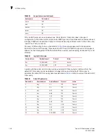
SCC policy states are shown in 

Table 30

.

Virtual Fabric considerations: In a logical fabric environment the SCC policy enforcement is not 
done on the logical ISL. For a logical ISL-based switch, the SCC policy enforcement is considered as 
the reference and the logical ISL is formed if the SCC enforcement passes on the extended ISL. The 
following functionality changes:

A logical switch supports an SCC policy. You can configure and distribute an SCC policy on a 
logical switch.

SCC enforcement is performed on a ISL based on the SCC policy present on the logical switch.

For more information on Virtual Fabrics, refer to 

Chapter 10, “Managing Virtual Fabrics”

.

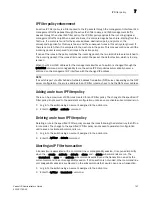
Creating an SCC policy

1. Connect to the switch and log in using an account assigned to the admin role.

2. Enter the secPolicyCreate “SCC_POLICY” command.

3. Save or activate the new policy by entering either the secPolicySave or the secPolicyActivate 

command.

If neither of these commands is entered, the changes are lost when the session is logged out. 

Example  of creating an SCC policy

For example, to create an SCC policy that allows switches that have domain IDs 2 and 4 to join 
the fabric:

switch:admin> 

secpolicycreate "SCC_POLICY", "2;4"

SCC_POLICY has been created
switch:admin> 

secpolicysave

TABLE 30

SCC policy states

Policy state

SCC policy enforcement

No active policy

All switches can connect to the switch with the specified policy.

Active policy that has no members

All neighboring switches are segmented.

Active policy that has members

The neighboring switches not specified in the SCC policy are 
segmented.

Summary of Contents for 53-1001763-02

Page 1: ...53 1001763 02 13 September 2010 Fabric OS Administrator s Guide Supporting Fabric OS v6 4 0 ...

Page 2: ...en source software is included in Brocade products view the licensing terms applicable to the open source software and obtain a copy of the programming source code please visit http www brocade com support oscd Brocade Communications Systems Incorporated Document History Corporate and Latin American Headquarters Brocade Communications Systems Inc 130 Holger Way San Jose CA 95134 Tel 1 408 333 8000...

Page 3: ...008 Fabric OS Administrator s Guide 53 1000598 03 Added Fabric OS v6 1 0 features Added support for new hardware platforms Brocade 5300 5100 and 300 12 March 2008 Fabric OS Administrator s Guide 53 1000598 04 Updated document to streamline content No new hardware or Fabric OS features 18 July 2008 Fabric OS Administrator s Guide 53 1001185 01 Added Fabric OS v 6 2 0 software features and support f...

Page 4: ...iv Fabric OS Administrator s Guide 53 1001763 02 ...

Page 5: ... 1 Understanding Fibre Channel Services In this chapter 3 Fibre Channel services overview 3 The Management Server 4 Platform services 4 Platform services in a Virtual Fabric 5 Enabling platform services 5 Disabling platform services 5 Management server database 5 Displaying the management server ACL 6 Adding a member to the ACL 6 Deleting a member from the ACL 7 Viewing the contents of the managem...

Page 6: ... 20 Virtual Fabrics and the Ethernet interface 20 Displaying the network interface settings 21 Static Ethernet addresses 22 DHCP activation 23 IPv6 autoconfiguration 24 Date and time settings 25 Setting the date and time 25 Time zone settings 26 Network time protocol 27 Domain IDs 28 Displaying the domain IDs 29 Setting the domain ID 30 Switch names 30 Customizing the switch name 30 Chassis names ...

Page 7: ...n blade compatibility 46 FX8 24 compatibility notes 48 Enabling and disabling blades 48 Enabling blades 48 Disabling blades 50 Blade swapping 50 Swapping blades 51 Swapping blades 52 Power management 53 Powering off a port blade 53 Powering on a port blade 53 Equipment status 54 Checking switch operation 54 Verifying High Availability features directors and enterprise class platforms only 54 Verif...

Page 8: ...in order frame delivery across topology changes 78 Restoring out of order frame delivery across topology changes78 Lossless Dynamic Load Sharing on ports 79 Lossless core 80 Configuring Lossless Dynamic Load Sharing 80 Lossless Dynamic Load Sharing in Virtual Fabrics 80 Frame Redirection 81 Creating a frame redirect zone 82 Deleting a frame redirect zone 82 Viewing redirect zones 82 Chapter 5 Mana...

Page 9: ...he RADIUS server 102 The RADIUS server 105 LDAP configuration and Microsoft Active Directory 111 Authentication servers on the switch 114 Configuring local authentication as backup 115 Chapter 6 Configuring Protocols In this chapter 117 Security protocols 117 Secure Copy 118 Setting up SCP for configUploads and downloads 119 Secure Shell protocol 119 SSH public key authentication 120 Secure Socket...

Page 10: ...39 DCC policies 140 DCC policy restrictions 141 Creating a DCC policy 141 Deleting a DCC policy 142 SCC policies 143 Creating an SCC policy 143 Authentication policy for fabric elements 144 E_Port authentication 145 Device authentication policy 147 AUTH policy restrictions 147 Authentication protocols 148 Secret key pairs for DH CHAP 149 FCAP configuration overview 150 Fabric wide distribution of ...

Page 11: ...nfiguration file in interactive mode 179 Configuration file restoration 180 Restrictions 180 Configuration download without disabling a switch 182 Configurations across a fabric 184 Downloading a configuration file from one switch to another same model switch 184 Security considerations 184 Configuration management for Virtual Fabrics 184 Uploading a configuration file from a switch with Virtual F...

Page 12: ...load 207 Chapter 10 Managing Virtual Fabrics In this chapter 209 Virtual Fabrics overview 209 Logical switch overview 210 Default logical switch 210 Logical switches and fabric IDs 212 Port assignment in logical switches 212 Logical switches and connected devices 213 Logical fabric overview 214 Logical fabric and ISLs 215 Logical fabric and ISL sharing 216 Management model for logical switches 219...

Page 13: ...rations 242 Zoning enforcement 242 Considerations for zoning architecture 243 Best practices for zoning 244 Broadcast zones 244 Broadcast zones and Admin Domains 244 Broadcast zones and FC FC routing 245 High availability considerations with broadcast zones 246 Loop devices and broadcast zones 246 Broadcast zones and default zoning 246 Zone aliases 246 Creating an alias 246 Adding members to an al...

Page 14: ...tation and zoning 263 Security and zoning 263 Zone merging scenarios 264 Chapter 12 Traffic Isolation Zoning In this chapter 267 Traffic Isolation Zoning overview 267 TI zone failover 268 FSPF routing rules and traffic isolation 270 Enhanced TI zones 272 Traffic Isolation Zoning over FC routers 273 TI within an edge fabric 274 TI within a backbone fabric 275 Limitations of TI zones over FC routers...

Page 15: ...ic mode configuration restrictions 301 McDATA Open Fabric mode configuration restrictions 302 Interoperability support for logical switches 302 Switch configurations for interoperability 303 Enabling McDATA Open Fabric mode 303 Enabling McDATA Fabric mode 304 Enabling Brocade Native mode 305 Zone management in interoperable fabrics 306 Zoning restrictions 306 Zone name restrictions 307 Zoning mode...

Page 16: ...nvironment 323 Coordinated Hot Code Load 324 Bypassing the Coordinated HCL check on firmware download324 Coordinated HCL on switches firmware downloads 325 Upgrade and downgrade considerations for HCL for interoperability 325 McDATA aware features 325 McDATA unaware features 326 M EOS feature limitations in mixed fabrics 328 Supported hardware in an interoperable environment 329 Supported features...

Page 17: ...nt AD context 357 Displaying an Admin Domain configuration 358 Switching to a different Admin Domain context 358 Admin Domain interactions with other Fabric OS features 359 Admin Domains zones and zone databases 360 Admin Domains and LSAN zones 362 Configuration upload and download in an AD context 362 Section II Licensed Features Chapter 16 Administering Licensing In this chapter 365 Licensing ov...

Page 18: ...ask for an end to end monitor 387 Deleting end to end monitors 388 Frame monitoring 389 Creating frame types to be monitored 390 Deleting frame types 391 Adding frame monitors to a port 391 Removing frame monitors from a port 391 Saving frame monitor configuration 391 Displaying frame monitors 392 Clearing frame monitor counters 392 ISL performance monitoring 393 Top Talker monitors 393 Adding a T...

Page 19: ...c prioritization over FC routers 415 Disabling QoS 416 Bottleneck detection 416 Supported configurations for bottleneck detection 417 How bottlenecks are reported 417 Limitations of bottleneck detection 417 High availability considerations for bottleneck detection 417 Upgrade and downgrade considerations for bottleneck detection418 Trunking considerations for bottleneck detection 418 Virtual Fabri...

Page 20: ...441 Long distance fabrics overview 441 Extended Fabrics device limitations 442 Long distance link modes 442 Configuring an extended ISL 443 Enabling long distance when connecting to TDM devices 444 Buffer credit management 445 Buffer to Buffer flow control 445 Optimal buffer credit allocation 446 Fibre Channel gigabit values reference definition 447 Allocating buffer credits based on full size fra...

Page 21: ...d FCR 477 Zone definition and naming 477 LSAN zones and fabric to fabric communications 478 Controlling device communication with the LSAN 478 Setting the maximum LSAN count 480 Configuring backbone fabrics for interconnectivity 481 HA and downgrade considerations for LSAN zones 481 LSAN zone policies using LSAN tagging 481 LSAN zone binding 485 Proxy PID configuration 489 Fabric parameter conside...

Page 22: ...agement interface507 Setting the IP address for the GE Inband Management interface507 Adding an Inband Management route on the CP 507 Deleting an Inband Management route 508 Viewing Inband Management IP addresses and routes 508 FIPS 509 Examples of supported configurations 509 Configuring a Management Station on the same subnet 509 Configuring a Management Station on different subnets 510 Appendix...

Page 23: ... the switch for FIPS 527 Overview of steps 527 Enabling FIPS mode 528 Disabling FIPS mode 529 Zeroizing for FIPS 530 Displaying FIPS configuration 530 Appendix E Hexadecimal Hexadecimal overview 531 Example conversion of the hexadecimal triplet Ox616000 531 Index ...

Page 24: ...xxiv Fabric OS Administrator s Guide 53 1001763 02 ...

Page 25: ...guration 166 Figure 20 Switch before and after enabling Virtual Fabrics 211 Figure 21 Switch before and after creating logical switches 211 Figure 22 Fabric IDs assigned to logical switches 212 Figure 23 Assigning ports to logical switches 213 Figure 24 Logical switches connected to devices and non Virtual Fabric switch 214 Figure 25 Logical switches in a single chassis belong to separate fabrics ...

Page 26: ...ined Admin Domains AD1 and AD2 354 Figure 57 AD0 with three zones 354 Figure 58 Setting end to end monitors on a port 386 Figure 59 Proper placement of end to end performance monitors 387 Figure 60 Mask positions for end to end monitors 388 Figure 61 QoS traffic prioritization 407 Figure 62 QoS with E_Ports enabled 408 Figure 63 Traffic prioritization in a logical fabric 409 Figure 64 Distribution...

Page 27: ...Fabric OS Administrator s Guide xxvii 53 1001763 02 Figure 79 Inband Management process 506 Figure 80 Management Station on same subnet 509 Figure 81 Management Station on a different subnet 511 ...

Page 28: ...xxviii Fabric OS Administrator s Guide 53 1001763 02 ...

Page 29: ... of simultaneous sessions 87 Table 14 Default local user accounts 88 Table 15 Authentication configuration options 100 Table 16 Syntax for VSA based account roles 102 Table 17 dictionary brocade file entries 103 Table 18 Secure protocol support 117 Table 19 Items needed to deploy secure protocols 118 Table 20 Main security scenarios 118 Table 21 SSL certificate files 123 Table 22 Blocked listener ...

Page 30: ...ons of ID domain offsets in IM2 300 Table 55 Internal representations of ID domain offsets in IM3 300 Table 56 Fabric OS switch authentication types 312 Table 57 Fabric OS mode descriptions 312 Table 58 DH group types 312 Table 59 Device authentication mode 313 Table 60 Switch authentication policy when all secrets are correct 313 Table 61 Switch authentication policy Fabric OS switch with incorre...

Page 31: ...trunking considerations 435 Table 90 Address identifier 438 Table 91 Fibre Channel data frames 447 Table 92 Buffer credits 451 Table 93 Configurable distances for Extended Fabrics 452 Table 94 Supported platforms and VF mode for masterless EX_Port trunking 475 Table 95 LSAN information stored in each FC router with and without LSAN zone binding 486 Table 96 Fabric OS and M EOSc interoperability co...

Page 32: ...xxxii Fabric OS Administrator s Guide 53 1001763 02 ...

Page 33: ...vanced Configuration Tasks provides advanced connection and configuration procedures Chapter 4 Routing Traffic provides information and procedures for using switch routing features Chapter 5 Managing User Accounts provides information and procedures on managing authentication and user accounts for the switch management channel Chapter 6 Configuring Protocols provides procedures for basic password ...

Page 34: ... of the Brocade Adaptive Networking suite of tools including Traffic Isolation QoS Ingress Rate Limiting and QoS SID DID Traffic Prioritization Chapter 19 Managing Trunking Connections provides procedures for use of the Brocade ISL Trunking licensed feature Chapter 20 Managing Long Distance Fabrics provides procedures for use of the Brocade Extended Fabrics licensed feature Chapter 21 Using the FC...

Page 35: ...s Brocade VA 40FC switch Information on device login behavior 10 bit addressing mode enhancements WWN based PID assignment enhancements NPIV enhancements Blade compatibility Loss Dynamic Load Sharing enhancements FCAP authentication enhancements Port indexing enhancements Bottleneck detection enhancements Information that was deleted Managing iSCSI Gateway Service which provides procedures for cre...

Page 36: ...n which a command is case sensitive Command syntax conventions Command syntax in this manual follows these conventions Notes cautions and warnings The following notices and statements are used in this manual They are listed below in order of increasing severity of potential hazards NOTE A note provides a tip guidance or advice emphasizes important information or provides a reference to related inf...

Page 37: ... www snia org education dictionary Notice to the reader This document may contain references to the trademarks of the following corporations These trademarks are the properties of their respective companies and corporations These references are made for informational purposes only Additional information This section lists additional Brocade and industry specific documentation that you might find h...

Page 38: ...ormation about the Fibre Channel industry visit the Fibre Channel Industry Association Web site http www fibrechannel org Getting technical help Contact your switch support supplier for hardware firmware and software support including product repairs and part ordering To expedite your call have the following information available 1 General Information Switch model Switch operating system version E...

Page 39: ... If you cannot use the wwn command because the switch is inoperable you can get the WWN from the same place as the serial number except for the Brocade DCX enterprise class platform For the Brocade DCX enterprise class platform access the numbers on the WWN cards by removing the Brocade logo plate at the top of the nonport side of the chassis For the Brocade 5424 embedded switch Provide the licens...

Page 40: ...xl Fabric OS Administrator s Guide 53 1001763 02 ...

Page 41: ...nced Configuration Tasks Chapter 4 Routing Traffic Chapter 5 Managing User Accounts Chapter 6 Configuring Protocols Chapter 7 Configuring Security Policies Chapter 8 Maintaining the Switch Configuration File Chapter 9 Installing and Maintaining Firmware Chapter 10 Managing Virtual Fabrics Chapter 11 Administering Advanced Zoning Chapter 12 Traffic Isolation Zoning Chapter 13 Administering NPIV Cha...

Page 42: ...2 Fabric OS Administrator s Guide 53 1001763 02 ...

Page 43: ...The Fabric Login server assigns a fabric address This allows a fabric node to communicate with services on the switch or other nodes in the fabric The fabric address assigned to a nodes is a 24 bit address 0x000000 containing three 3 byte long nodes Reading from left to right the first node 0x000000 represents the domain ID the second node 0x000000 the port area number of the port where the node i...

Page 44: ...ames identifying switches can be registered with the management server The management server provides several advantages for managing a Fibre Channel fabric It is accessed by an external Fibre Channel node at the well known address FFFFFAh so an application can access information about the entire fabric management with minimal knowledge of the existing configuration It is replicated on every Broca...

Page 45: ...e the next step will fail 3 Enter the msplMgmtActivate command switch admin msplmgmtactivate Request to activate MS Platform Service in progress Completed activating MS Platform Service in the fabric Disabling platform services 1 Connect to the switch and log in using an account assigned to the admin role 2 Enter the msplMgmtDeactivate command 3 Enter y to confirm the deactivation switch admin msp...

Page 46: ...dd member based on its Port Node WWN 3 Delete member based on its Port Node WWN select 0 3 1 0 done Adding a member to the ACL 1 Connect to the switch and log in using an account assigned to the admin role 2 Enter the msConfigure command The command becomes interactive 3 At the select prompt enter 2 to add a member based on its port node WWN 4 At the Port Node WWN prompt enter the WWN of the host ...

Page 47: ...rt Node WWN 3 Delete member based on its Port Node WWN select 0 3 1 0 done Update the FLASH yes y no n yes y Successfully saved the MS ACL to the flash Deleting a member from the ACL 1 Connect to the switch and log in as admin 2 Enter the msConfigure command The command becomes interactive 3 At the select prompt enter 3 to delete a member based on its port node WWN 4 At the Port Node WWN prompt en...

Page 48: ...in role 2 Enter the msPlatShow command Example of viewing the contents of the management server platform database switch admin msplatshow Platform Name 9 first obj Platform Type 5 GATEWAY Number of Associated M A 1 35 http java sun com products plugin Number of Associated Node Names 1 Associated Node Names 10 00 00 60 69 20 15 71 Platform Name 10 second obj Platform Type 7 HOST_BUS_ADAPTER Number ...

Page 49: ...tch admin mstdenable Request to enable MS Topology Discovery Service in progress MS Topology Discovery enabled locally switch admin mstdenable ALL Request to enable MS Topology Discovery Service in progress MS Topology Discovery enabled locally MS Topology Discovery Enable Operation Complete Disabling topology discovery 1 Connect to the switch and log in as admin 2 Enter the appropriate following ...

Page 50: ...e fabric such as a zoning change or a change in the state of a device to which this device has access the device will receive a Registered State Change Notification RSCN Registration A device exchanges registration information with the Name Server Query Devices query the Name Server for information about the device it can access Principal switch In a fabric with multiple switches and one inter swi...

Page 51: ...all unidentified or uninitiated ports are listed as U_Ports L_ FL_Port A loop or fabric loop port connects loop devices L_Ports are associated with private loop devices and FL_Ports are associated with public loop devices G_Port A generic port acts as a transition port for non loop fabric capable devices E_Port An expansion port is assigned to ISL links to expand your fabric by connecting it to ot...

Page 52: ...Name Server commands refer to the Fabric OS Command Reference RSCN causes An Registered State Change Notification RSCN is a notification frame that is sent to devices that are zoned together and are registered to receive a State Change Notification SCN The RSCN is responsible for notifying all devices of fabric changes The following general list of actions can cause an RSCN to be sent through your...

Page 53: ...ty daemon logs error detection reporting handling and presentation of data into a format readable by you and management tools rpcd Remote Procedure Call daemon used by the API Fabric Access API and SMI S snmpd Simple Network Management Protocol daemon traced Trace daemon provides trace entry date time translation to Trace Device at startup and when date time changed by command Maintains the trace ...

Page 54: ...14 Fabric OS Administrator s Guide 53 1001763 02 High availability of daemon processes 1 ...

Page 55: ...ing a SAN using the CLI you can also use the following methods to configure a SAN Web Tools For Web Tools procedures see the Web Tools Administrator s Guide Data Center Fabric Manager DCFM For DCFM procedures see the Data Center Fabric Manager Professional User Manual or Data Center Fabric Manager Enterprise User Manual depending on the version you have A third party application using the API For ...

Page 56: ... RBAC role you need to run a command review the section Role Based Access Control RBAC on page 84 NOTE When command examples in this guide show user input enclosed in quotation marks the quotation marks are required Console sessions using the serial port Note the following behaviors for serial connections Some procedures require that you connect through the serial port for example setting the IP a...

Page 57: ...sions are active if you do your next attempt to log in fails To recover gain access to the switch by one of these methods You can use Web Tools to perform a fast boot When the switch comes up the Telnet quota is cleared For instructions on performing a fast boot with Web Tools see the Web Tools Administrator s Guide If you have the required privileges you can connect through the serial port log in...

Page 58: ...lp command a list of all user level commands that can be executed is displayed The same rule applies to the admin securityAdmin and the switchAdmin roles 1 Connect to the switch and log in using an account assigned to the admin role 2 Enter the help more command with no specific command and all commands will be displayed The more argument displays the commands one page at a time Or you can enter h...

Page 59: ...cters the period and the underscore _ They are case sensitive and they are not displayed when you enter them on the command line Record the passwords exactly as entered and store them in a secure place because recovering passwords requires significant effort and fabric downtime Although the root and factory accounts are not meant for general use change their passwords if prompted to do so and save...

Page 60: ... the serial port to maintain your session through the change You must connect through the serial port to set the Ethernet IP address if the Ethernet network interface is not configured already Refer Connecting to Fabric OS through the serial port on page 16 for details Virtual Fabrics and the Ethernet interface On the Brocade 48000 DCX and DCX 4S the single chassis IP address and subnet mask are a...

Page 61: ...4 IPFC address for virtual fabric ID 45 13 1 2 4 20 Slot 7 eth0 11 1 2 4 24 Gateway 11 1 2 1 Backplane IP address of CP0 10 0 0 5 Backplane IP address of CP1 10 0 0 6 IPv6 Autoconfiguration Enabled Yes Local IPv6 Addresses sw 0 stateless fd00 60 69bc 70 260 69ff fe00 2 64 preferred sw 0 stateless fec0 60 69bc 70 260 69ff fe00 2 64 preferred cp 0 stateless fd00 60 69bc 70 260 69ff fe00 197 64 prefe...

Page 62: ...work interface 1 Connect to the switch and log in using an account assigned to the admin role 2 Perform the appropriate action based on whether you have a switch or enterprise class platform If you are setting the IP address for a switch enter the ipAddrSet command If you are setting the IP address for an enterprise class platform enter the ipAddrSet command specifying either CP0 or CP1 You must s...

Page 63: ...ass identifier is the string BROCADE followed by the SWBD model number of the platform For example the vendor class identifier for a request from a Brocade 5300 is BROCADESWBD64 NOTE The client conforms to the latest IETF Draft Standard RFCs for IPv4 IPv6 and DHCP Enabling DHCP Connect the DHCP enabled switch to the network power on the switch and the switch automatically obtains the Ethernet IP a...

Page 64: ... disable it by entering off Example of disabling DHCP switch admin ipaddrset Ethernet IP Address 10 1 2 3 Ethernet Subnetmask 255 255 255 0 Fibre Channel IP Address 220 220 220 2 Fibre Channel Subnetmask 255 255 0 0 Gateway IP Address 10 1 2 1 DHCP On off IPv6 autoconfiguration IPv6 can assign multiple IP addresses to each network interface Each interface is configured with a link local address in...

Page 65: ...r any static IPv6 addresses have been configured Setting IPv6 autoconfiguration 1 Connect to the switch and log in using an account assigned to the admin role 2 Take the appropriate following action based on whether you want to enable or disable IPv6 autoconfiguration Enter the ipAddrSet ipv6 auto command to enable IPv6 autoconfiguration for all managed entities on the target platform Enter the ip...

Page 66: ...o the prior time zone format For more information about the tsTimeZone command refer to the Fabric OS Command Reference When you set the time zone for a switch you can perform the following tasks Display all of the time zones supported in the firmware Set the time zone based on a country and city combination or based on a time zone ID l such as PST The time zone setting has the following character...

Page 67: ...nect to the switch and log in using an account assigned to the admin role and with the chassis role permission 2 Enter the tsTimeZone interactive command You are prompted to select a general location Please identify a location so that time zone rules can be set correctly 3 Enter the appropriate number or press Ctrl D to quit 4 At the prompt select a country location 5 At the prompt enter the appro...

Page 68: ...r if the active NTP server fails The principal or primary FCS switch synchronizes its time with the NTP server every 64 seconds 1 Connect to the switch and log in using an account assigned to the admin role 2 Enter the tsClockServer command switch admin tsclockserver ntp1 ntp2 In this syntax ntp1 is the IP address or DNS name of the first NTP server which the switch must be able to access The seco...

Page 69: ...fc02 10 00 00 60 69 e0 01 46 10 3 220 1 0 0 0 0 ras001 3 fffc03 10 00 00 60 69 e0 01 47 10 3 220 2 0 0 0 0 ras002 5 fffc05 10 00 00 05 1e 34 01 bd 10 3 220 5 0 0 0 0 ras005 fec0 60 69bc 63 205 1eff fe34 1bd 6 fffc06 10 00 00 05 1e 34 02 3e 10 3 220 6 0 0 0 0 ras006 7 fffc07 10 00 00 05 1e 34 02 0c 10 3 220 7 0 0 0 0 ras007 10 fffc0a 10 00 00 05 1e 39 e4 5a 10 3 220 10 0 0 0 0 ras010 15 fffc0f 10 0...

Page 70: ... by customized switch names that are unique and meaningful Switch names can be from 1 to 30 characters long All switch names must begin with a letter and can contain letters numbers or the underscore character It is not necessary to use quotation marks NOTE Changing the switch name causes a domain address format RSCN to be issued and may be disruptive to the fabric Customizing the switch name 1 Co...

Page 71: ...s and switch initialization routines have finished You can disable and re enable it as necessary Disabling a switch 1 Connect to the switch and log in using an account assigned to the admin role 2 Enter the switchDisable command All Fibre Channel ports on the switch are taken offline If the switch was part of a fabric the fabric is reconfigured Enabling a switch 1 Connect to the switch and log in ...

Page 72: ...runlevel 0 INIT Sending processes the TERM signal Unmounting all filesystems The system is halted flushing ide devices hda Power down 5 Power off the switch Powering off a Brocade enterprise class platform 1 From the active CP in a dual CP platform enter the sysShutdown command NOTE When the sysShutdown command is issued on the active CP the active CP the standby CP and any AP blades are all shut ...

Page 73: ...nnection To minimize port logins power off all devices before connecting them to the switch When powering the devices back on wait for each device to complete the fabric login before powering on the next one For devices that cannot be powered off first use the portDisable command to disable the port on the switch connect the device and then use the portEnable command to enable the port Switch conn...

Page 74: ...34 Fabric OS Administrator s Guide 53 1001763 02 Basic connections 2 ...

Page 75: ...g it into a different port as part of fabric maintenance or changing the domain ID of a switch which might be necessary when merging fabrics or changing compatibility mode settings Some device drivers use the PID to map logical disk drives to physical Fibre Channel counterparts Most drivers can either change PID mappings dynamically also called dynamic PID binding or use the WWN of the Fibre Chann...

Page 76: ... default partition With fixed addressing mode enabled each port has a fixed address assigned by the system based on the port number This address does not change unless you choose to swap the address using the portSwap command 10 bit addressing mode This is the default mode for all the logical switches created in the Brocade DCX and DCX 4S enterprise class platforms This addressing scheme is flexib...

Page 77: ...ogical switch WWN based PID assignment WWN based PID assignment is disabled by default When the feature is enabled bindings are created dynamically as new devices log in they automatically enter the WWN based PID database The bindings exist until you explicitly unbind the mappings through the CLI or change to a different addressing mode If there are any existing devices when you enable the feature...

Page 78: ...ID across reboots and AL_PAs assigned for the device do not depend on the order in which the devices come up Refer to Chapter 13 Administering NPIV for more information on NPIV Enabling automatic PID assignment NOTE To activate the WWN based PID assignment you do not need to disable the switch 1 Connect to the switch and log in using an account assigned to the admin role 2 Enter the configure comm...

Page 79: ... Data Center Backbone Hardware Reference Manual respectively The different blades that can be inserted into a chassis are described as follows Control processor blades CPs contain communication ports for system management and are used for low level platform wide tasks In the Brocade 48000 CPs are used for intra platform switching Core blades in the Brocade DCX CORE8 and DCX 4S CR4S 8 are used for ...

Page 80: ...on the right set of ports FC10 6 Ports are numbered from 0 through 5 from bottom to top FC4 16IP Fibre Channel ports are numbered from 0 through 7 from bottom to top There are also 8 GbE ports numbered ge0 ge7 from bottom to top Going from bottom to top the 8 FC ports appear on the bottom followed by the 8 GbE ports at the top FA4 18 Fibre Channel ports are numbered from 0 through 15 from bottom t...

Page 81: ...port 1 is 1 and so forth For 32 port blades FC4 32 FC8 32 the numbering is contiguous up to port 15 from port 16 the numbering is still contiguous but starts with 128 For example port 15 in slot 1 has a port number and area ID of 15 port 16 has a port number and area ID of 128 port 17 has a port number and area ID of 129 For 48 port blades FC4 48 FC8 48 the numbering is the same as for 32 port bla...

Page 82: ...port The device can then be plugged into the new port without the need to reboot the device Use the following procedure to swap the port area IDs of two physical switch ports In order to swap port area IDs the port swap feature must be enabled and both switch ports must be disabled The swapped area IDs for the two ports remain persistent across reboots power cycles and failovers Brocade 48000 and ...

Page 83: ... disabled enter the command portCfgPersistentEnable portnumber or portCfgPersistentEnable slotnumber portnumber If you change port configurations during a switch failover the ports may become disabled To bring the ports online re issue the portEnable command after the failover is complete Disabling a port 1 Connect to the switch and log in using an account assigned to the admin role 2 Enter the ap...

Page 84: ...The third generation CP blade provided with the Brocade 48000 This CP supports 1 2 4 8 and 10 Gbps port speeds as well as 16 32 and 48 port blades Brocade DCX and DCX 4S control processor blade CP8 50 The CP blade provided with the Brocade DCX This CP supports 1 2 4 8 and 10 Gbps port speeds as well as 16 32 48 and 64 port blades Note These blades are interchangeable between the Brocade DCX and DC...

Page 85: ...patible only with the Brocade 48000 CP blades using chassis configuration option 5 and the Brocade DCX and DCX 4S CP blades Fibre Channel Router blade FR4 18i 24 A 16 port Fibre Channel routing and FCIP blade that also has 2 GbE ports and is compatible only with the Brocade 48000 using chassis configuration option 5 and the Brocade DCX and DCX 4S CP blades iSCSI Bridge blade FC4 16IP 31 An iSCSI b...

Page 86: ...m have only one type of CP blade installed and that each CP primary and secondary partition maintains the same firmware version For more information on maintaining firmware in your enterprise class platform refer to Chapter 9 Installing and Maintaining Firmware Core blades Core blades provide intra chassis switching and ICL connectivity between DCX platforms The Brocade DCX supports two CORE8 core...

Page 87: ...ic OS v6 3 0 Fabric OS v6 4 0 DCX DCX 4S DCX DCX 4S DCX DCX 4S FR4 18i1 1 On the Brocade 48000 the blade can co exist with an FC4 16IP but the iSCSI devices are not exported and imported for FC routing services The iSCSI functionality over FCIP is not supported but the FCIP link is the same as other FC E_Ports This is not restricted by software 8 4 8 4 8 4 FA4 182 2 The hardware limit is enforced ...

Page 88: ... FX8 24 and vice versa without rebooting or power cycling the chassis will fault the blade with reason code 91 However after blade removal if you reboot or power cycle the chassis inserting the other blade type is allowed The data paths in both blades are interoperable between FC ports FR4 18i FC ports can stream data over FX8 24 GbE ports and vice versa The FX8 24 blade cannot co exist with the F...

Page 89: ...e ports use the previous configuration and come up enabled If you do not want to use the previous configuration you must clear the configuration information remove the blade and then reseat the blade If a previously configured FR4 18i blade is removed and an FC4 48 FC8 16 FC8 32 FC8 48 or FC10 6 blade is plugged in then other than the port s EX_Port configuration all the remaining port configurati...

Page 90: ...e Fabric OS then validates each command before actually implementing the command on the enterprise class platform If an error is encountered then blade swap quits without disrupting traffic flowing through the blades If an unforeseen error does occur during the bladeSwap command an entry will be made into the RASlog and all ports that have been swapped as part of the blade swap operation will be s...

Page 91: ...ication to application etc Port Count Both blades must support the same number of front ports For example 16 ports to 16 ports 32 ports to 32 ports 48 ports to 48 ports and so on Availability The ports on the destination blade must be available for the swap operation and not attached to any other devices 3 Port preparation The process of preparing ports for a swap operation includes basic operatio...

Page 92: ...al switches as long as they are carved the same way If slot 1 and slot 2 ports 0 7 are all in the same logical switch then blade swapping slot 1 to slot 2 will work The entire blade does not need to be in the same partition FIGURE 4 Blade swap with Virtual Fabrics after the swap Swapping blades 1 Connect to the director and log in using an account assigned to the admin role 2 Enter the bladeSwap c...

Page 93: ...owered up in the reverse order During the initial power up of a chassis or using the slotPowerOn command or the insertion of a blade the available power is compared to required power before power is applied to the blade NOTE Some FRUs in the chassis may use significant power yet cannot be powered off through software For example a missing blower FRU may change the power computation enough to affec...

Page 94: ...3 Enter the haShow command to verify HA is enabled the heartbeat is up and that the HA state is synchronized between the active and standby CP blades 4 Enter the fanShow to display the current status and speed of each fan in the system Refer to the hardware reference manual of your system to determine the appropriate values 5 Enter the psShow to display the current status of the switch power suppl...

Page 95: ...y AP BLADE The blade is the FR4 18i blade UNKNOWN The blade is not present or its type is not recognized ID Displays the hardware ID of the blade type See Table 4 on page 44 for a list of blades and their corresponding IDs Model Name Displays the model name of the blade Status Displays the status of the blade DIAG RUNNING POST1 The blade is present powered on and running the post initialization po...

Page 96: ...eature allows you to keep a record of specific changes that may not be considered switch events but may provide useful information The output from the track changes feature is dumped to the system messages log for the switch Use the errDump or errShow command to view the log Items in the log created from the Track changes feature are labeled TRCK Trackable changes are Successful login Unsuccessful...

Page 97: ...h to MARGINAL or DOWN For example if the FaultyPorts DOWN parameter is set to 3 the status of the switch will change if three ports fail Only one policy parameter needs to pass the MARGINAL or DOWN threshold to change the overall status of the switch For more information about setting policy parameters see the Fabric Watch Administrator s Guide 1 Connect to the switch and log in using an account a...

Page 98: ...n Marginal PowerSupplies 3 0 Temperatures 2 1 Fans 2 1 WWN 0 1 CP 0 1 Blade 0 1 CoreBlade 0 1 Flash 0 1 MarginalPorts 112 44 FaultyPorts 112 44 MissingSFPs 0 0 Note that the value 0 for a parameter means that it is NOT used in the calculation In addition if the range of settable values in the prompt is 0 0 the policy parameter is NOT applicable to the switch Simply hit the Return key The minimum n...

Page 99: ...stem message log The filtered events are streamed chronologically and sent to the system message log on an external host in the specified audit message format This ensures that they can be easily distinguished from other system message log events that occur in the network Then at some regular interval of your choosing you can review the audit events to look for unexpected changes Before you config...

Page 100: ...tive domain of the entity that generated the event Refer to the Fabric OS Message Reference for details on message formats For more information on setting up the system error log daemon refer to the Fabric OS Troubleshooting and Diagnostics Guide Verifying host syslog prior to configuring the audit log Audit logging assumes that your syslog is operational and running Before configuring an audit lo...

Page 101: ...ent logging based on the classes configured in step 2 switch admin auditcfg enable Audit filter is enabled To disable an audit event configuration enter the auditCfg disable command 4 Enter the auditCfg show command to view the filter configuration and confirm that the correct event classes are being audited and the correct filter state appears enabled or disabled switch admin auditcfg show Audit ...

Page 102: ...62 Fabric OS Administrator s Guide 53 1001763 02 Audit log configuration 3 ...

Page 103: ...stination network There are two kinds of routing protocols on intranet networks Distance Vector and Link State Distance Vector is based on hop count This is the number of switches that a frame passes through to get from the source switch to the destination switch Link State is based on a metric value based on a cost The cost could be based on bandwidth line speed or round trip time With the link s...

Page 104: ... switches in the fabric by adding the cost of all links traversed by the path and chooses the path that minimizes the costs This collection of the link states including costs of all the switches in the fabric constitutes the topology database or link state database Once established FSPF programs the hardware routing tables for all active ports on the switch FSPF is not involved in frame switching ...

Page 105: ...nel frame to perform what is known as cut through routing A frame may begin to emerge from the output port before it has been entirely received by the input port The entire frame does not need to be buffered in the switch If the destination domain ID is different than the source domain ID then the switch consults the FSPF route table to identify which local E_Port provides the Fabric Shortest Path...

Page 106: ... to existing fabric You can connect new switches to existing switches and this expands your fabric Figure 6 shows a new switch being added into an existing fabric The thicker red line is the newly formed ISL When connecting two switches together you need to verify that the following parameters are different Domain ID Switch name Chassis name You must also verify the following fabric parameters are...

Page 107: ...d When a device logs into a fabric it typically requests anywhere from two to sixteen buffer credits from the switch depending on device type driver version and configuration This determines the maximum number of frames the port may transmit before receiving an acknowledgement from the receiving device For more information on how to set the buffer to buffer credits on an extended link refer to Cha...

Page 108: ...ble in Fabric OS QoS allows the prioritization of data traffic based on the SID DID of each frame Through the use of QoS zones traffic can be divided into three priorities high medium and low The seven data VC channels VC8 14 are used to multiplex data frames based upon QoS Zones when congestion occurs For more information on QoS zones refer to Chapter 18 Optimizing Fabric Behavior ...

Page 109: ...establishing point to point E_Port connectivity between two Fibre Channel switches that are separated by a network with a protocol such as IP or SONET Except for link initialization gateways are transparent to switches the gateway simply provides E_Port connectivity from one switch to another Figure 9 shows two separate SANs A 1 and A 2 merged together using a gateway ...

Page 110: ...es are followed All switches in the fabric are using the core PID format as described in Configuring a link through a gateway on page 70 The switches connected to both sides of the gateway are included when determining switch count maximums Extended links those created using the Extended Fabrics licensed feature are not supported through gateway links Configuring a link through a gateway 1 Connect...

Page 111: ... proprietary connectors instead of traditional SFPs When two Brocade Backbones are interconnected by ICLs each chassis still requires a unique domain and is managed as a separate switch On the Brocade DCX there are two ICL connectors at ports ICL0 and ICL1 on each core blade each aggregating a set of 16 ports Thus each core blade provides 32 ICL ports and there are 64 ICL ports available for the e...

Page 112: ...ameters associated with ICL ports are static and all portCfg commands are blocked from changing any of the ICL port parameters The only management associated with ICL ports and cables is monitoring the status of the LEDs on the ICL ports and any maintenance if the ATTENTION LED is blinking yellow For additional information about the LED status for blades and ports see the Brocade DCX Hardware Inst...

Page 113: ...and default switch The triangular topology requirement still needs to be met for each fabric individually The present restriction on ICL being part of only logical switches with Allow XISL Use attribute off still applies Routing policies By default all routing protocols place their routes into a routing table You can control the routes that a protocol places into each table and the routes from tha...

Page 114: ...d Fibre Channel originator exchange ID OXID optimizing path utilization for the best performance Thus every exchange can take a different path through the fabric Exchange based routing requires the use of the Dynamic Load Sharing DLS feature when this policy is in effect you cannot disable the DLS feature Exchange based routing is also known as Dynamic Path Selection DPS DPS is where exchanges or ...

Page 115: ...ffic going through both directions at the same time There is a reduction of the effect of slow devices on the overall switch performance It is recommended that the default AP Shared Link Policy be used for most environments Also it is recommended that you design a SAN that localizes Host to Target traffic by reducing the amount of traffic through the router Two additional AP policies are supported...

Page 116: ... constantly adjust to changing network conditions or it may be static so that data packets always follow a predetermined path Dynamic Load Sharing The exchange based routing policy depends on the Fabric OS Dynamic Load Sharing feature DLS for dynamic routing path selection When using the exchange based routing policy DLS is enabled by default and cannot be disabled In other words you cannot enable...

Page 117: ...in dlsreset switch admin dlsshow DLS is not set Static route assignment A static route can be assigned only when the active routing policy is port based routing When exchange based routing is active you cannot assign static routes Static routes are supported only on the Brocade 4100 and 5000 platforms Static routes are not supported on the Brocade 300 4900 5410 5424 5450 5460 5470 5480 5100 5300 5...

Page 118: ...routing policy In a stable fabric frames are always delivered in order even when the traffic between switches is shared among multiple paths However when topology changes occur in the fabric for example if a link goes down traffic is rerouted around the failure and some frames could be delivered out of order Most destination devices tolerate out of order delivery but some do not By default out of ...

Page 119: ... takes effect if DLS is enabled Lossless DLS can be enabled on fabric topology in order to have zero frame drops during rebalance operations If the end device also requires the order of frames to be maintained during the rebalance operation then IOD needs to be enabled However this combination of Lossless DLS and IOD is supported only in specific topologies such as in a FICON environment You can d...

Page 120: ...ion The path between an FC10 6 FA4 18 and FR4 18i blade and an FX8 24 blade or vice versa will experience I O disruption because the FC10 6 FA4 18 and FR4 18i blades do not support this feature Configuring Lossless Dynamic Load Sharing You configure Lossless DLS switch or chassis wide by using the dlsSet command to specify that no frames are dropped while rebalancing or rerouting traffic 1 Connect...

Page 121: ... logical switches that require Lossless DLS only using supported blades For example do not use blades that support IOD but do not support Lossless DLS For more information on Virtual Fabrics and chassis level permissions see the Managing Virtual Fabrics chapter NOTE Downgrading from Fabric OS v6 2 0 is not supported if Lossless DLS is enabled If you have Lossless DLS is enabled but DLS IOD and por...

Page 122: ...fined configuration Example of creating a frame redirect zone The following example creates an RD Zone given a host 10 10 10 10 10 10 10 10 target 20 20 20 20 20 20 20 20 VI 30 30 30 30 30 30 30 30 and VT 40 40 40 40 40 40 40 40 switch admin zone rdcreate 10 10 10 10 10 10 10 10 20 20 20 20 20 20 20 20 30 30 30 30 30 30 30 30 40 40 40 40 40 40 40 40 restartable noFCR Deleting a frame redirect zone...

Page 123: ...logged in to by default The home Admin Domain must be a member of the user s Admin Domain list Role Determines functional access levels within the bounds of the user s current Admin Domain Virtual Fabric list Specifies the Virtual Fabric a user account is allowed to log in to Home Virtual Fabric Specifies the Virtual Fabric that the user is logged in to by default The home Virtual Fabric must be a...

Page 124: ...level of access you have on that switch and in the fabric The chassis role permission is not a role like the other role types but a permission that is applied to a user account You can use the userConfig command to add this permission to a user account For clarity this permission has been added to Table 10 which outlines the Fabric OS predefined roles Admin Domain considerations Legacy users with ...

Page 125: ...nge and delete objects on the system such as running userConfig change username r rolename to change a user s role OM Observe and Modify The user can run commands using both observe and modify options if a role has modify permissions it almost always has observe N None The user is not allowed to run commands in a given category TABLE 12 RBAC permissions matrix Category Role permission Admin Basic ...

Page 126: ...I OM O OM O N O O O License OM O OM OM O OM O O LDAP OM N N N OM OM N N Local User Environment OM OM OM OM OM OM OM OM Logging OM O OM OM OM OM O O Management Access Configuration OM O OM OM N OM O N Management Server OM O OM OM N OM O O Name Server OM O OM O N OM O O Nx_Port Management OM O OM OM N OM O N Physical Computer System O O O O O O O O PKI OM O O O OM O O N Port Mirroring OM N N N N N N...

Page 127: ...M O OM OM OM OM O O Switch Management OM O OM OM O OM O O Switch Management IP Configuration OM O OM OM OM OM O N Switch Port Configuration OM OM OM OM O OM O O Switch Port Management OM OM OM OM O OM O O Topology OM O OM O N O O N USB Management OM N N N OM N N N User Management OM N N N OM N N N WWN Card OM N OM OM N OM O N Zoning OM O OM O O O O OM 1 Only with the chassis role permission added ...

Page 128: ...t that is a subset of the administrator Displaying account information 1 Connect to the switch and log in using an account assigned to the admin role 2 Enter the appropriate show operands for the account information you want to display userConfig show a to show all account information for a logical switch userConfig show username to show account information for the specified account userConfig sho...

Page 129: ...r the userConfig change command Local account passwords The following rules apply to changing passwords Users can change their own passwords Only users with Admin roles can change the password for another account When changing an Admin account password you must provide the current password An admin with ADlist 0 10 or LFlist 1 10 cannot change the password on an admin user or any role with an ADli...

Page 130: ...itches has logical switches defined Distributing the local user database When distributing the local user database all user defined accounts residing in the receiving switches are logged out of any active sessions 1 Connect to the switch and log in using an account assigned to the admin role 2 Enter the distribute p PWD d command NOTE If Virtual Fabrics mode is enabled and there are logical switch...

Page 131: ...default passwords Password strength policy The password strength policy is enforced across all user accounts and enforces a set of format rules to which new passwords must adhere The password strength policy is enforced only when a new password is defined The total of the other password strength policy parameters lowercase uppercase digits and punctuation must be less than or equal to the value of...

Page 132: ...a password strength policy The following example shows a password strength policy that requires passwords to contain at least 3 uppercase characters 4 lowercase characters and 2 numeric digits the minimum length of the password is 9 characters passwdcfg set uppercase 3 lowercase 4 digits 2 minlength 9 Password history policy The password history policy prevents users from recycling recently used p...

Page 133: ...er to zero disables password expiration Warning Specifies the number of days prior to password expiration that a warning about password expiration is displayed Warning values range from 0 to 999 The default value is 0 days NOTE When MaxPasswordAge is set to a non zero value MinPasswordAge and Warning must be set to a value that is less than or equal to MaxPasswordAge Account lockout policy The acc...

Page 134: ... duration begins with the first login attempt after the LockoutThreshold has been reached Subsequent failed login attempts do not extend the lockout period Enabling the admin lockout policy 1 Log in to the switch using an account that is an Admin role or securityAdmin role 2 Enter the passwdCfg enableadminlockout command Unlocking an account 1 Log in to the switch using an account that is an Admin...

Page 135: ...e switch until the switch is rebooted Perform this procedure during a planned downtime Setting the boot PROM password for a switch with a recovery string This procedure applies to the following switch models Brocade 300 4100 4900 5000 5410 5424 5450 5460 5470 5480 5100 5300 7500 7500E 7600 7800 and 8000 switches If your switch is not listed please contact your switch support provider for instructi...

Page 136: ... and DCX 4S enterprise class platforms 1 Connect to the serial port interface on the standby CP blade as described in Connecting to Fabric OS through the serial port on page 16 2 Connect to the active CP blade by serial or Telnet and enter the haDisable command to prevent failover during the remaining steps 3 Reboot the standby CP blade by sliding the On Off switch on the ejector handle of the sta...

Page 137: ...blade by serial or Telnet and enter the haEnable command to restore high availability Although you can set the boot PROM password without also setting the recovery string it is strongly recommended that you set both the password and the string as described in Setting the boot PROM password for a switch with a recovery string on page 95 If your site procedures dictate that you must set the boot PRO...

Page 138: ... active now standby CP blade to minimize disruption to the fabric 1 Determine the active CP blade by opening a Telnet session to either CP blade connecting as admin and entering the haShow command 2 Connect to the active CP blade by serial or Telnet and enter the haDisable command to prevent failover during the remaining steps 3 Create a serial connection to the standby CP blade as described in Co...

Page 139: ...configured to try both RADIUS or LDAP and local switch authentication When configured to use either RADIUS or LDAP the switch acts as a network access server NAS and RADIUS or LDAP client The switch sends all authentication authorization and accounting AAA service requests to the RADIUS or LDAP server The RADIUS or LDAP server receives the request validates the request and sends its response back ...

Page 140: ...bric OS mechanisms for changing switch passwords remain functional however such changes affect only the involved switches locally They do not propagate to the RADIUS or LDAP server nor do they affect any account on the RADIUS or LDAP server When RADIUS or LDAP is set up for a fabric that contains a mix of switches with and without RADIUS or LDAP support the way a switch authenticates users depends...

Page 141: ...trative Domain is assigned then the user is assigned to the default Admin Domain AD0 authspec radius local backup Authenticates management connections against any RADIUS databases If RADIUS fails because the service is not available it then authenticates against the local user database The backup option directs the service to try the secondary authentication database only if the primary authentica...

Page 142: ...al switch user accounts and passwords remain functional when the switch is configured to use RADIUS Changes made to the local switch database do not propagate to the RADIUS server nor do the changes affect any account on the RADIUS server TABLE 16 Syntax for VSA based account roles Item Value Description Type 26 1 octet Length 7 or higher 1 octet calculated by the server Vendor ID 1588 4 octet Bro...

Page 143: ...alled dictionary brocade After you have completed the dictionary file define the role for the user in a configuration file For example to grant the user jsmith the Admin role you would add the following statement to the configuration file swladmin Auth Type Local User Password myPassword Brocade Auth Role admin Brocade AVPairs1 HomeLF 70 Brocade AVPairs2 LFRoleList admin 2 4 8 70 80 128 ChassisRol...

Page 144: ...ltiple occurrences of the same Admin Domain number are ignored HomeLF is the designated home Virtual Fabric for the account The valid values are between 1 to 128 and chassis context The first valid HomeLF key value pair is accepted by the switch additional HomeLF key value pairs are ignored LFRoleList is a comma separated list of Virtual Fabric ID numbers to which this account is a member Valid nu...

Page 145: ...in the RADIUS server configuration User accounts should be set up by their true network wide identity rather than by the account names created on a Fabric OS switch Along with each account name the administrator must assign appropriate switch access roles To manage a fabric these roles can be User Admin and SecurityAdmin Configuring RADIUS server support with Linux The following procedures work fo...

Page 146: ...ADIUS The user will log in using the role specified with Brocade Auth Role The valid roles include Root Admin SwitchAdmin ZoneAdmin SecurityAdmin BasicSwitchAdmin FabricAdmin Operator and User You must use quotation marks around password and role Example of adding a user name to the RADIUS authentication For example to set up an account called JohnDoe with the Admin role with a password expiry dat...

Page 147: ...iusd Configuring RADIUS server support with Windows 2000 The instructions for setting up RADIUS on a Windows 2000 server are listed here for your convenience but are not guaranteed to be accurate for your network environment Always check with your system administrator before proceeding with setup NOTE All instructions involving Microsoft Windows 2000 can be obtained from www microsoft com or your ...

Page 148: ...ote Access Policies folder then select New Remote Access Policy from the pop up window A remote access policy must be created for each Brocade login role Root Admin Factory SwitchAdmin and User for which you want to use RADIUS Apply this policy to the user groups that you already created c In the Vendor Specific Attribute Information window enter the vendor code value 1588 Click the Yes It conform...

Page 149: ...to the RSA RADIUS server a Add the following data to the vendor ini file vendor product Brocade dictionary brocade ignore ports no port number usage per port type help id 2000 b Create a brocade dct file that needs to be added into the dictiona dcm file located in the following path C Program Files RSA Security RSA RADIUS Service Figure 14 on page 110 shows what the brocade dct file should look li...

Page 150: ... of this file Use the Radius specification attributes in lieu of the Brocade one radius dct MACRO Brocade VSA t s 26 vid 1588 type1 t len1 2 data s ATTRIBUTE Brocade Auth Role Brocade VSA 1 string r ATTRIBUTE Brocade Passwd ExpiryDate Brocade VSA 6 string r ATTRIBUTE Brocade Passwd WarnPeriod Brocade VSA 7 integer r brocade dct Brocade Dictionary dictiona dcm Generic Radius radius dct Specific Imp...

Page 151: ... of the groups has the same name as the Brocade role name Among those groups one group name must match with either the Brocade role or be mapped to a switch role in the Brocade switch A user can be part of any Organizational Unit OU Active Directory LDAP 2000 2003 and 2003 is supported Roles for Brocade specific users can be added through the Microsoft Management Console Groups created in Active D...

Page 152: ...r To create a user in Active Directory refer to www microsoft com or Microsoft documentation There are no special attributes to set You can use a fully qualified name for logging in for example you can log in as user domain com Creating a group To create a group in Active Directory refer to www microsoft com or Microsoft documentation You will need to verify that the group has the following attrib...

Page 153: ...e the first value in the adlist Admin Domain list If a user has no values assigned in the adlist attribute then the homeAD 0 will be the default administrative domain for the user If you are using Virtual Fabrics enter the value of the logical fabric separated by an semi colon into the Value field Example for adding Virtual Fabrics HomeLF 10 LFRoleList admin 128 10 ChassisRole admin In this exampl...

Page 154: ...guration is in effect This configuration is persistent after an HA failover The RADIUS or LDAP servers are contacted in the order they are listed starting from the top of the list and moving to the bottom Adding a RADIUS or LDAP server to the switch configuration 1 Connect to the switch and log in using an account assigned to the admin role 2 Enter the aaaConfig add command At least one RADIUS or ...

Page 155: ...able local authentication so that the switch can take over authentication locally if the RADIUS or LDAP servers fail to respond because of power outage or network problems Example of enabling local authentication enter the following command for RADIUS switch admin aaaconfig authspec radius local backup Example for LDAP switch admin aaaconfig authspec ldap local backup For details about this comman...

Page 156: ...116 Fabric OS Administrator s Guide 53 1001763 02 The authentication model using RADIUS and LDAP 5 ...

Page 157: ...BLE 18 Secure protocol support Protocol Description HTTPS HTTPS is a Uniform Resource Identifier scheme used to indicate a secure HTTP connection Web Tools supports the use of hypertext transfer protocol over secure socket layer HTTPS IPsec Internet Protocol Security IPsec is a framework of open standards for providing confidentiality authentication and integrity for IP data transmitted over untru...

Page 158: ...nable SSL Supports SSLv3 128 bit encryption by default TABLE 19 Items needed to deploy secure protocols Protocol Host side Switch side SSHv2 Secure shell client None HTTPS No requirement on host side except a browser that supports HTTPS Switch IP certificate for SSL SCP SSH daemon SCP server None SNMPv1 SNMPv2 SNMPv3 None None TABLE 20 Main security scenarios Fabric Management interfaces Comments ...

Page 159: ...ing login The SSH package contains a daemon sshd which runs on the switch The daemon supports a wide variety of encryption algorithms such as Blowfish Cipher block chaining CBC and Advanced Encryption Standard AES NOTE To maintain a secure network you should avoid using Telnet or any other unprotected application when you are working on the switch The File Transfer Protocol FTP is also not secure ...

Page 160: ...ey pair for an outgoing connection and delete public and private keys After the allowed user is changed all the public keys related to the old allowed user are lost Configuring SSH authentication Incoming authentication is used when the remote host needs to authenticate to the switch Outgoing authentication is used when the switch needs to authenticate to a server or remote host more commonly used...

Page 161: ...ted successfully 6 Generate a key pair for switch to host outgoing authentication by logging in to the switch as the allowed user and entering the sshUtil genkey command You may enter a passphrase for additional security Example of generating a key pair on the switch switch alloweduser sshutil genkey Enter passphrase empty for no passphrase Enter same passphrase again Key pair generated successful...

Page 162: ...suing CA If you change a switch IP address or FQDN after activating an associated certificate you may have to obtain and install a new certificate Check with the CA to verify this possibility and plan these types of changes accordingly Browser and Java support Fabric OS supports the following Web browsers for SSL connections Internet Explorer v7 0 Microsoft Windows Mozilla Firefox v2 0 Solaris and...

Page 163: ...e Authority 5 On each switch install the certificate Once the certificate is loaded on the switch HTTPS starts automatically 6 If necessary install the root certificate to the browser on the management workstation 7 Add the root certificate to the Java Plug in keystore on the management workstation Certificate authorities To ease maintenance and allow secure out of band communication between switc...

Page 164: ...mation Example of generating a CSR Country Name 2 letter code eg US US State or Province Name full name eg California California Locality Name eg city name San Jose Organization Name eg company name Brocade Organizational Unit Name eg department name Eng Common Name Fully qualified Domain Name or IP address 192 1 2 3 Generating CSR file name is 192 1 2 3 csr Done Your CA may require specific codes...

Page 165: ...ncluding the BEGIN and END lines into the area provided in the request form then follow the instructions to complete and send the request It may take several days to receive the certificates If the certificates arrive by e mail save them to an FTP server If the CA provides access to the certificates on an FTP server make note of the path name and make sure you have a login name and password on the...

Page 166: ...ist to see if the root certificate is listed For example its name may have the form nameRoot crt Take the appropriate following action based on whether you find the certificate If the certificate is listed you do not need to install it You can skip the rest of this procedure If the certificate is not listed click Import 5 Browse to the certificate location and select the certificate For example se...

Page 167: ...nt accesses MIB information about a device and makes it available to a network management station You can manipulate information of your choice by trapping MIB elements using the Fabric OS command line interface CLI Web Tools or DCFM The SNMP access control list ACL provides a way for the administrator to restrict SNMP get set trap and inform operations to certain hosts and IP addresses This is us...

Page 168: ...local switch database SNMPv3 users whose names do not match with any of the existing Fabric OS local users have a default RBAC role of admin with the SNMPv3 user access control of read write Their SNMPv3 user logs in with an access control of read only Both user types will have the default switch as their home Virtual Fabrics The contextName field should have the format VF xxx where xxx is the act...

Page 169: ...ions loading instructions and information about using the Brocade SNMP agent see the Fabric OS MIB Reference Telnet protocol Telnet is enabled by default To prevent passing clear text passwords over the network when connecting to the switch you can block the Telnet protocol using an IP Filter policy For more information on IP Filter policies refer to IP Filter policy on page 153 ATTENTION Before b...

Page 170: ... policy should be displayed as defined switch admin ipfilter show Name BlockTelnet Type ipv4 State defined Rule Source IP Protocol Dest Port Action 1 any tcp 23 deny 2 any tcp 22 permit 3 any tcp 22 permit 4 any tcp 897 permit 5 any tcp 898 permit 6 any tcp 111 permit 7 any tcp 80 permit 8 any tcp 443 permit 9 any udp 161 permit 10 any udp 111 permit 11 any udp 123 permit 12 any tcp 600 1023 permi...

Page 171: ...d listener applications Listener application Brocade 48000 director and Brocade DCX enterprise class platforms Brocade 300 4100 4900 5000 5410 5424 5450 5460 5470 5480 5100 5300 5424 7500 7500E 7600 7800 8000 and VA 40FC switches FA4 18 FC4 16 FC4 16IP FC4 32 FC4 48 FC8 16 FC8 32 FC8 48 FC10 6 FCOE10 24 FR4 18i FS8 18 and FX8 24 blades chargen Disabled Disabled echo Disabled Disabled daytime Disab...

Page 172: ... the fabric All switches in the fabric can be accessed through a serial port Zoning No zoning is enabled TABLE 24 Port information Port Type Common use Comment 22 TCP SSH SCP 23 TCP Telnet Use the ipfilter command to block the port 80 TCP HTTP Use the ipfilter command to block the port 111 UDP sunrpc This port is used by Platform API Use the ipfilter command to block the port 123 UDP NTP 161 UDP S...

Page 173: ...ed to restrict which Fibre Channel device ports can connect to which Fibre Channel switch ports Switch connection control SCC policy Used to restrict which switches can join with a switch NOTE Run all commands in this chapter by logging in to Administrative Domain AD 255 with the suggested role If Administrative Domains have not been implemented log in to AD0 How the ACL policies are stored The po...

Page 174: ...embers are specified by device port WWN switch WWN domain IDs or switch names depending on the policy The valid methods for specifying policy members are listed in Table 25 ACL policy management All policy modifications are temporarily stored in volatile memory until those changes are saved or activated You can create multiple sessions to the switch from one or more hosts It is recommended you mak...

Page 175: ...and This saves the changes to the active policy set and activates all policy changes since the last time the command was issued You cannot activate policies on an individual basis all changes to the entire policy set are activated by the command Until a secPolicySave or secPolicyActivate command is issued all policy changes are in volatile memory only and are lost upon rebooting 1 Connect to the s...

Page 176: ...LICY_abc 11 22 33 44 55 66 77 aa 11 22 33 44 55 66 77 bb 3 1 3 Removing a member from an ACL policy As soon as a policy has been activated the aspect of the fabric managed by that policy is enforced 1 Connect to the switch and log in using an account assigned to the admin role 2 Enter the secPolicyRemove command 3 To implement the change immediately enter the secPolicyActivate command Example of r...

Page 177: ...istributed across the fabric only the Primary FCS switch can perform certain operations Operations that affect fabric wide configuration are allowed only from the Primary FCS switch Backup and non FCS switches cannot perform security zoning and AD operations that affect the fabric configuration The following error message is returned if a backup or non FCS switch tries to perform these operations ...

Page 178: ...s a switch with domain ID 2 to become a primary FCS and domain ID 4 to become a backup FCS switch admin secpolicycreate FCS_POLICY 2 4 FCS_POLICY has been created 3 To save or activate the new policy enter either the secPolicySave or the secPolicyActivate command Once the policy has been activated you can distribute the policy TABLE 27 FCS switch operations Allowed on FCS switches Allowed on all s...

Page 179: ...Name 1Yes 10 00 00 60 69 10 02 181 switch5 2No 10 00 00 60 69 00 00 5a2 switch60 3No 10 00 00 60 69 00 00 133 switch73 Please enter position you d like to move from 1 3 1 2 Please enter position you d like to move to 1 3 1 3 ____________________________________________________ DEFINED POLICY SET FCS_POLICY PosPrimaryWWN DId swName __________________________________________________ 1Yes 10 00 00 60...

Page 180: ... will be accepted and distribution may be initiated using the distribute p command Setting the configuration parameter to reject indicates the policy distribution is rejected and the switch may not distribute the policy The default value for the distribution configuration parameter is accept which means the switch accepts all database distributions and is able to initiate a distribute operation fo...

Page 181: ... including the prefix DCC_POLICY_ Device ports must be specified by port WWN Switch ports can be identified by the switch WWN domain ID or switch name followed by the port or area number To specify an allowed connection enter the device port WWN a semicolon and the switch port identification The following methods of specifying an allowed connection are possible deviceportWWN switchWWN port or area...

Page 182: ...rts of switch domain 2 and all currently connected devices of switch domain 2 switch admin secpolicycreate DCC_POLICY_storage 22 33 44 55 66 77 11 bb 2 DCC_POLICY_storage has been created To create the DCC policy DCC_POLICY_abc that includes device 33 44 55 66 77 11 22 cc and ports 1 through 6 and port 9 of switch domain 3 switch admin secpolicycreate DCC_POLICY_abc 33 44 55 66 77 11 22 cc 3 1 6 9...

Page 183: ...functionality changes A logical switch supports an SCC policy You can configure and distribute an SCC policy on a logical switch SCC enforcement is performed on a ISL based on the SCC policy present on the logical switch For more information on Virtual Fabrics refer to Chapter 10 Managing Virtual Fabrics Creating an SCC policy 1 Connect to the switch and log in using an account assigned to the adm...

Page 184: ...tch with Fabric OS v6 2 0 or later to use DH CHAP for device authentication When you configure DH CHAP authentication you also must define a pair of shared secrets known to both switches as a secret key pair Figure 16 illustrates how the secrets are configured A secret key pair consists of a local secret and a peer secret The local secret uniquely identifies the local switch The peer secret unique...

Page 185: ...rting authentication on all E_Ports on the local switch if the policy is changed to ON or ACTIVE and clearing the authentication if the policy is changed to OFF The authentication configurations will be effective only on subsequent E_ and F_Port initialization ATTENTION A secret key pair has to be installed prior to changing the policy For more information on setting up secret key pairs refer to S...

Page 186: ...cy is set to ACTIVE Re authenticating E_Ports Use the command authUtil to re initiate the authentication on selected ports It provides flexibility to initiate authentication for specified E_Ports a set of E_Ports or all E_Ports on the switch This command does not work on loop NPIV and FICON devices The command authUtil can re initiate authentication only if the device was previously authenticated ...

Page 187: ... the AUTH_NEGOTIATE is completed all ELS and CT frames except the AUTH_NEGOTIATE ELS frame are blocked by the switch During this time the Fibre Channel driver rejects all other ELS frames The F_Port does not form until the AUTH_NEGOTIATE is completed It is the HBA s responsibility to send an Authentication Negotiation ELS frame after receiving the FLOGI accept frame with the FC SP bit set Virtual ...

Page 188: ...for a switch Run the authUtil command on the switch you want to view or change Below are the different options to specify which DH group you want to use 00 DH Null option 01 1024 bit key 02 1280 bit key 03 1536 bit key 04 2048 bit key Viewing the current authentication parameter settings for a switch 1 Log in to the switch using an account assigned to the admin role 2 Enter the authUtil show Examp...

Page 189: ...is not set up for a link authentication fails The Authentication Failed reason code 05h error will be reported and logged The minimum length of a shared secret is 8 bytes and the maximum length is 40 bytes NOTE When setting a secret key pair note that you are entering the shared secrets in plain text Use a secure channel for example SSH or the serial console to connect to the switch on which you a...

Page 190: ...name Leave blank when done 10 20 30 40 50 60 70 80 Enter peer secret hidden Re enter peer secret hidden Enter local secret hidden Re enter local secret hidden Enter WWN Domain or switch name Leave blank when done 10 20 30 40 50 60 70 81 Enter peer secret hidden Re enter peer secret hidden Enter local secret hidden Re enter local secret hidden Enter WWN Domain or switch name Leave blank when done c...

Page 191: ... key the CSR and the passphrase 1 Log in to the switch using an account assigned to the admin role 2 Enter the secCertUtil generate fcapall keysize command on the local switch switch admin seccertutil generate fcapall keysize 1024 WARNING About to create FCAP ARE YOU SURE yes y no n no y Installing Private Key and Csr Switch key pair and CSR generated 3 Repeat step 2 on the remote switch Exporting...

Page 192: ...must be installed prior to installing the switch certificate 1 Log in to the switch using an account assigned to the admin role 2 Enter the secCertUtil import fcapcacert command switch admin seccertutil import fcapswcert Select protocol ftp or scp scp Enter IP address 10 1 2 3 Enter remote directory myHome jdoe OPENSSL Enter certificate name must have crt or cer pem or psk suffix 01 pem Enter Logi...

Page 193: ...cy for each IP type can be activated on the affected management IP interfaces Audit messages will be generated for any changes to the IP Filter policies The rules in the IP Filter policy are examined one at a time until the end of the list of rules For performance reasons the most important rules must be specified at the top On a chassis system changes to persistent IP Filter policies are automati...

Page 194: ...icy name is optional for this subcommand If the policy name is given the IP Filter policy in the temporary buffer is saved if the policy name is not given all IP Filter policies in the temporary buffer are saved Only the CLI session that owns the updated temporary buffer may run this command Modification to an active policy cannot be saved without being applied Hence the save subcommand is blocked...

Page 195: ...ches any IPv4 address In addition the keyword any is supported to represent any IPv4 address For an IPv6 filter policy the source address has to be a 128 bit IPv6 address in a format acceptable in RFC 3513 The group prefix has to be a CIDR block prefix representation For example 12AB 0 0 CD30 64 represents a 64 bit IPv6 prefix starting from the most significant bit In addition the keyword any is s...

Page 196: ...d A switch with Fabric OS v6 2 0 or later will have a default IP Filter policy for IPv4 and IPv6 The default IP Filter policy cannot be deleted or changed When an alternative IP Filter policy is activated the default IP Filter policy becomes deactivated Table 34 lists the rules of the default IP Filter policy snmp 161 ssh 22 sunrpc 111 telnet 23 www 80 TABLE 33 Implicit IP Filter rules Source addr...

Page 197: ...f a switch is part of a LAN behind a Network Address Translation NAT server depending on the NAT server configuration the source address in an IP Filter rule may have to be the NAT server address Adding a rule to an IP Filter policy There can be a maximum of 256 rules created for an IP Filter policy The change to the specified IP Filter policy is not saved to the persistent configuration until a s...

Page 198: ...havior The ACL policy database is managed as follows Switch database distribution setting Controls whether or not the switch accepts or rejects databases distributed from other switches in the fabric The distribute command sends the database from one switch to another overwriting the target switch database with the distributed one To send or receive a database the setting must be accept For config...

Page 199: ...olicy Absent default Tolerant Strict Reject Database is protected it cannot be overwritten May not match other databases in the fabric Invalid configuration 1 1 An error is returned indicating that the distribution setting must be accept before you can set the fabric wide consistency policy Invalid configuration 1 Accept default Database is not protected the database can be overwritten If the swit...

Page 200: ...e distribution settings on page 159 The fabric must have a tolerant or no absent fabric wide consistency policy see Fabric wide enforcement on page 160 If the fabric wide consistency policy for a database is strict the database cannot be manually distributed When you set a strict fabric wide consistency policy for a database the distribution mechanism is automatically invoked whenever the database...

Page 201: ...abric wide consistency policy 1 Connect to the switch and log in using an account assigned to the admin role 2 Enter the fddCfg showall command Example shows policies for a fabric where no consistency policy is defined switch admin fddcfg showall Local Switch Configuration for all Databases DATABASE Accept Reject SCC accept DCC accept PWD accept FCS accept AUTH accept IPFILTER accept Fabric Wide C...

Page 202: ...bwideset command to resolve the fabric wide consistency policy conflicts Use the distribute command to explicitly resolve conflicting ACL policies When a switch is joined to a fabric with a strict SCC or DCC fabric wide consistency policy the joining switch must have a matching fabric wide consistency policy If the strict SCC or DCC fabric wide consistency policies do not match the switch cannot j...

Page 203: ...on matching strict policy and the merge fails and the ports are disabled Table 39 on page 164 shows merges that are not supported TABLE 38 Merging fabrics with matching fabric wide consistency policies Fabric wide consistency policy Fabric A ACL policies Fabric B ACL policies Merge results Database copied None None None Succeeds No ACL policies copied None SCC DCC Succeeds No ACL policies copied T...

Page 204: ...l IP networks through the use of cryptographic security services The goal of IPsec is to provide the following capabilities Authentication Ensures that the sending and receiving end users and devices are known and trusted by one another Data Integrity Confirms that the data received was in fact the data transmitted Data Confidentiality Protects the user data being transmitted such as utilizing enc...

Page 205: ...n use to implement an IPsec tunnel between two devices You can configure other scenarios as nested combinations of these configurations Endpoint to Endpoint Transport or Tunnel In this scenario both endpoints of the IP connection implement IPsec as required of hosts in RFC4301 The transport mode is commonly used with no inner IP header If there is an inner IP header the inner addresses will be the...

Page 206: ...tunnel all of its traffic back through the corporate network in order to take advantage of protection provided by a corporate firewall against Internet based attacks In either case the protected endpoint will want an IP address associated with the security gateway so that packets returned to it will go to the security gateway and be tunneled back FIGURE 19 Endpoint to gateway tunnel configuration ...

Page 207: ...rbitrary 32 bit value contained in IPsec protocol headers AH or ESP and an IPsec SA is unidirectional Because most communication is peer to peer or client to server two SAs must be present to secure traffic in both directions An SA specifies the IPsec protocol AH or ESP the algorithms used for encryption and authentication and the expiration definitions used in security associations of the traffic...

Page 208: ...cryption and authentication algorithms to be used in security associations when IKE is used as the key management protocol IPsec can protect either the entire IP datagram or only the upper layer protocols The appropriate modes are called tunnel mode and transport mode In tunnel mode the IP datagram is fully encapsulated by a new IP datagram using the IPsec protocol In transport mode only the paylo...

Page 209: ...utomatic keyed connections The LINUX setKey command can be used for manually keyed connections which means that all parameters needed for the setup of the connection are provided by you Based on which protocol algorithm and key used for the creation of the security associations the switch populates the security association database SAD accordingly Pre shared keys A pre shared key has the psk exten...

Page 210: ...lgorithm to be used on the tunnel Refer to Table 41 on page 168 to determine which algorithm to use in conjunction with a specific authentication protocol 2 Determine the type of keys to be used on the tunnel If you are using CA signed keys you must generate them prior to setting up your tunnels 3 Enable IPsec a Connect to the switch and log in using an account assigned to the admin role b Enter t...

Page 211: ...g add policy ips selector t SELECTOR OUT d out l 10 33 74 13 r 10 33 69 132 transform TRANSFORM01 switch admin ipsecconfig add policy ips selector t SELECTOR IN d in l 10 33 69 132 r 10 33 74 13 t transform TRANSFORM01 10 Verify traffic is protected a Initiate a telnet SSH or ping session from the two switches b Verify that IP traffic is encapsulated c Monitor IPsec SAs created using IKE for above...

Page 212: ...etime in time units switch admin ipsecconfig add policy ips sa proposal t IPSEC AH lttime 280000 sa AH01 6 Import the pre shared key file using the secCertUtil command The file name should have a psk extension For more information on importing the pre shared key file refer to Installing a switch certificate on page 125 7 Configure an IKE policy for the remote peer switch admin ipsecconfig add poli...

Page 213: ...command with the operands specified to display the outbound and inbound SAs in the kernel SADB Use the ipSecConfig show policy ips sa a command with the specified operands to display all IPsec SA policies Use the ipSecConfig show policy ips sa proposal a command with the specified operands to display IPsec proposals Use the ipSecConfig show policy ips transform a command with the specified operand...

Page 214: ...174 Fabric OS Administrator s Guide 53 1001763 02 Management interface security 7 ...

Page 215: ...puter server for emergency reference NOTE For information about AD enabled switches refer to Chapter 15 Managing Administrative Domains For more information about troubleshooting configuration file uploads and downloads refer to the Fabric OS Troubleshooting and Diagnostics Guide There are two ways to view configuration settings for a switch in a Brocade fabric Issue the configShow all command To ...

Page 216: ...itch information CAUTION If you have Virtual Fabrics enabled you must follow the procedure in Configuration management for Virtual Fabrics on page 184 to restore the logical switches Example of a configuration file Configuration upload Information Configuration Format 2 0 date Thu Apr 2 21 28 52 2009 FOS version v6 3 0 0 Number of LS 2 Chassis Configuration Begin fcRouting Chassis Configuration Li...

Page 217: ...ing Defined Security policies Active Security policies iSCSI cryptoDev FICU SAVED FILES Banner End Switch Configuration End 0 date Thu Apr 2 21 28 52 2009 Switch Configuration Begin 1 SwitchName switch_2 Fabric ID 1 Boot Parameters Configuration Bottleneck Configuration Zoning Defined Security policies Active Security policies iSCSI cryptoDev FICU SAVED FILES Banner End Switch Configuration End 1 ...

Page 218: ...irtual Fabric mode disabled and there are additional sections corresponding to each additionally defined logical switch instance on a switch with Virtual Fabric mode enabled These are the switch specific data that affect only that logical switch behavior The following components are in the switch section of the configuration file Boot parameters Configuration Bottleneck configuration FCOE configur...

Page 219: ...mmand becomes interactive and you are prompted for the required information 4 Store a soft copy of the switch configuration information in a safe place for future reference NOTE The configuration file is printable but you may want to see how many pages will be printed before you send it to the printer Example of configUpload on a switch without Admin Domains switch admin configupload Protocol scp ...

Page 220: ...anagement supports configDownload with Fabric OS v6 1 x or v6 2 0 configuration files Configuration files from a system running Fabric OS v6 2 0 are not backward compatible and cannot be downloaded to a Fabric OS v6 1 0 or earlier system Configuration files downloaded from a system running Fabric OS v6 2 0 to a system running v6 3 0 and to a system running Fabric OS v6 3 0 to a system running v6 4...

Page 221: ...enable each switch individually once the configuration download has completed Non Virtual Fabric configuration files downloaded to a Virtual Fabric system will only have configuration applied to the default switch If there are multiple logical switches created in a Virtual Fabric enabled system there could be some issues if there are ports that belong to the default switch in a Virtual Fabric disa...

Page 222: ...ot create logical switches if they do not exist Restoring a configuration CAUTION Using the SFID parameter erases all configuration information on the logical switch Use this parameter only when the logical switch has no configuration information you want to save 1 Verify that the FTP service is running on the server where the backup configuration file is located 2 Connect to the switch and log in...

Page 223: ... hidden configDownload complete Example of configDownload with Admin Domains switch AD5 admin configdownload Protocol scp or ftp ftp Server Name or IP Address host 10 1 2 3 User Name user UserFoo Path Filename home dir config txt pub configurations config txt CAUTION This command is used to download a backed up configuration for a specific switch If using a file from a different switch this file s...

Page 224: ...to another same model switch 1 Configure one switch 2 Use the configUpload command to save the configuration information Refer to Configuration file backup on page 178 for more information 3 Run configDefault on each of the target switches and then use the configDownload command to download the configuration file to each of the target switches Refer to Configuration file restoration on page 180 fo...

Page 225: ...X_80 FID128 admin configupload vf Protocol scp ftp local ftp Server Name or IP Address host 10 1 2 3 User Name user anonymous Path Filename home dir config txt configUpload complete VF config parameters are uploaded 2009 07 20 09 13 40 LOG 1000 225 SLOT 7 CHASSIS INFO BrocadeDCX Previous message repeated 7 time s 2009 07 20 10 27 14 CONF 1001 226 SLOT 7 FID 128 INFO DCX_80 configUpload completed s...

Page 226: ...nfiguration s for any logical switch s that are setup in the new VF configuration Do you want to continue y n y output truncated Restrictions The following restrictions should be observed when using the configUpload or configDownload commands when Virtual Fabrics is enabled The vf option is incompatible with the fid sfid or all options Any attempt to combine it with any of the other three will fai...

Page 227: ...guide for FC port setting tables The tables can be used to record configuration information for the various blades TABLE 43 Brocade configuration and connection Brocade configuration settings IP address Gateway address Chassis configuration option Management connections Serial cable tag Ethernet cable tag Configuration information Domain ID Switch name Ethernet IP address Ethernet subnet mask Tota...

Page 228: ...188 Fabric OS Administrator s Guide 53 1001763 02 Brocade configuration form 8 ...

Page 229: ... extra processors and specialized ports Brocade FR4 18i and FC4 16IP FA4 18 FCOE10 24 and FX8 24 CP blades have a control processor CP used to control the entire switch they can be inserted only into slots 5 and 6 on the Brocade 48000 slots 6 and 7 on the Brocade DCX and slots 4 and 5 on the Brocade DCX 4S CORE8 and CR4S 8 core blades provide ICL functionality between two Brocade DCX Backbones COR...

Page 230: ... to traffic flowing through the enterprise class platform This operation depends on HA status on the enterprise class platform If the platform does not support HA you can still upgrade the CPs one at a time If you are using a Brocade 48000 or a Brocade DCX or DCX 4S enterprise class platform with one or more AP blades The Fabric OS automatically detects mismatches between the active CP firmware an...

Page 231: ...rs when two CPs in an enterprise class platform are synchronized This state provides redundancy and a non disruptive firmware download In order for a firmware download to successfully occur the two CPs in an enterprise class platform must be in sync If the CPs have mixed versions when you enter the firmwareDownload command the CPs may not be in HA sync In this case you need to enter the firmwareDo...

Page 232: ...rading from Fabric OS v6 3 0 to v6 4 0 is supported but upgrading from Fabric OS v6 2 0 or a previous release directly to v6 4 0 is not In other words upgrading a switch from Fabric OS v6 2 0 to v6 4 0 is a two step process first upgrade to v6 3 0 and then upgrade to v6 4 0 If you are running a pre Fabric OS v6 2 0 you must upgrade to v6 2 0 then to v6 3 0 and finally to v6 4 0 3 Perform a configU...

Page 233: ...e contracts and for partners on the Brocade Web site at http www brocade com At the Brocade Web site click Brocade Connect log in and follow the instructions to register and download firmware Partners with authorized accounts can use the Brocade Partner Network You must decompress the firmware before you can use the firmwareDownload command to update the firmware on your equipment Use the UNIX tar...

Page 234: ...to the secondary partition The system performs a high availability reboot haReboot After the haReboot the former secondary partition is the primary partition The system replicates the firmware from the primary to the secondary partition Software application SA software is upgraded only when firmwareDownload is issued with the a an SA option Refer to the application s manual for further information...

Page 235: ...irmware if necessary before proceeding with upgrading this switch See Connected switches on page 192 for details 6 Enter the firmwareDownload command and respond to the prompts NOTE If DNS is enabled and a server name instead of a server IP address is specified in the command line firmwareDownload determines whether IPv4 or IPv6 should be used To be able to mention the FTP server by name you must ...

Page 236: ...rom different versions of v6 2 0 such as patch releases If you are downgrading from v6 2 0 to v6 1 x you must enter the firmwareDownload s command as described in Test and restore firmware on switches on page 203 This is not necessary when downgrading from Fabric OS v6 3 0 to v6 2 0 or from Fabric OS v6 4 0 to v6 3 0 During the upgrade process the director fails over to its standby CP blade and th...

Page 237: ...oad command automatically upgrades both the active and standby CP on the Brocade 48000 director It also automatically upgrades both the active and the standby CP and all co CPs on the CP blades in the Brocade DCX and DCX 4S Backbones It automatically upgrades all AP blades in the Brocade 48000 the Brocade DCX and DCX 4S platforms using auto leveling 1 Verify that the Ethernet interfaces located on...

Page 238: ... version of the firmware regardless of which version is older Autoleveling downloads firmware to the AP blade swaps partitions reboots the blade and copies the new firmware from the primary partition to the secondary partition If you have multiple AP blades they are updated simultaneously however the downloads can occur at different rates Autoleveling takes place in parallel with the firmware down...

Page 239: ...nal firmware image is relocated successfully 4 Mon Mar 22 04 35 30 2010 Slot 7 CP1 active Firmware has been downloaded to the secondary partition of the switch 5 Mon Mar 22 04 37 24 2010 Slot 7 CP1 standby The firmware commit operation has started This may take up to 10 minutes 6 Mon Mar 22 04 41 59 2010 Slot 7 CP1 standby The commit operation has completed successfully 7 Mon Mar 22 04 41 59 2010 ...

Page 240: ...ownload command downloads the specified firmware image from the USB device When specifying a path to a firmware image in the USB device you can only specify the relative path to firmware or the absolute path Enabling USB 1 Log in to the switch using an account assigned to the admin role 2 Enter the usbStorage e command Viewing the USB file system 1 Log in to the switch using an account assigned to...

Page 241: ...to the switch After it is downloaded it can be used to validate the firmware to be downloaded next time when you run the firmwareDownload command The public key file on the switch contains only one public key It is only able to validate firmware signed using one corresponding private key If the private key changes in future releases you need to change the public key on the switch by one of the fol...

Page 242: ...braries on the filesystem to be validated before Fabric OS modules are launched This is to make sure these files have not been changed after they are installed When firmware RPM packages are installed during firmwareDownload the MD5 checksums of the firmware files are stored in the RPM database on the filesystem The checksums go through all of the files in the RPM database Every file compares its ...

Page 243: ...d files preserving directory structures The firmware is in the form of RPM packages with names defined in a plist file that contains specific firmware information and the names of packages of the firmware to be downloaded 4 Connect to the switch and log in as admin 5 Enter the firmwareShow command to view the current firmware 6 Enter the firmwareDownload s command to update the firmware and respon...

Page 244: ... have the original firmware Note that it takes several minutes to complete the commit operation b Wait five minutes to ensure that all processes have completed and the switch is fully up and operational c Log in to the switch Enter the firmwareShow command and verify that both partitions on the switch have the original firmware Test and restore firmware on enterprise class platforms This procedure...

Page 245: ...t will take a minute or two for the standby CP to reboot and synchronize with the active CP CAUTION If you are downgrading from Fabric OS v6 2 0 to v6 1 0 your CPs will not gain synchronization and this will be a disruptive firmware download Refer to Table 44 on page 191 for more information on synchronization states c Enter the firmwareShow command to confirm that the primary partition of the sta...

Page 246: ...ndby CP enter the firmwareCommit command to update the secondary partition with new firmware It takes several minutes to complete the commit operation Do not do anything on the enterprise class platform while this operation is in process 11 Perform a commit on the active CP a From the current enterprise class platform session on the active CP enter the firmwareShow command and confirm that only th...

Page 247: ...the blade firmware is basically restored Your system is now restored to the original partitions on both CPs Make sure that servers using the fabric can access their storage devices If you want to upgrade an enterprise class platform with only one CP in it follow the procedures in Test and restore firmware on switches on page 203 Note however that upgrading an enterprise class platform with only on...

Page 248: ...an only run this command on the active CP When downloading Fabric OS the event logs in the two CPs are synchronized This command can be run from either CP nsShow Displays all devices directly connected to the switch that have logged into the name server Make sure the number of attached devices after the firmware download is exactly the same as the number of attached devices prior to the firmware d...

Page 249: ... switch 228 Adding and removing ports on a logical switch 229 Displaying logical switch configuration 230 Changing the fabric ID of a logical switch 230 Changing a logical switch to a base switch 231 Configuring a logical switch to use XISLs 232 Changing the context to a different logical fabric 233 Creating a logical fabric using XISLs 234 Virtual Fabrics overview Virtual Fabrics is an architectu...

Page 250: ...rtual Fabrics feature Logical switch overview Traditionally each switch and all the ports in the switch act as a single Fibre Channel switch FC switch that participates in a single fabric The logical switch feature allows you to divide a physical chassis into multiple fabric elements Each of these fabric elements is referred to as a logical switch Each logical switch functions as an independent se...

Page 251: ...ue to belong to the default logical switch until you explicitly move them to other logical switches The default logical switch always exists You can add and delete other logical switches but you cannot delete the default logical switch unless you disable Virtual Fabrics FIGURE 21 Switch before and after creating logical switches Before enabling Virtual Fabrics After enabling Virtual Fabrics Physic...

Page 252: ... change this value later NOTE Each logical switch is assigned one and only one FID The FID identifies the logical fabric to which the logical switch belongs FIGURE 22 Fabric IDs assigned to logical switches Port assignment in logical switches Initially all ports belong to the default logical switch When you create additional logical switches they are empty and you must assign ports to those logica...

Page 253: ...cal switch can have as many ports as are available in the chassis In Figure 23 the chassis has 10 ports You could assign all 10 ports to a single logical switch such as Logical switch 2 if you did this however then no ports would be available for Logical switches 3 and 4 You can move only F_Ports and E_Ports from one logical switch to another If you want to configure a different type of port such ...

Page 254: ...hes in a single chassis belong to separate fabrics If you want to allow device sharing across fabrics in a Virtual Fabrics environment see FC FC Routing and Virtual Fabrics on page 492 Logical fabric overview A logical fabric is a fabric that contains at least one logical switch The four fabrics shown in Figure 24 and Figure 25 are logical fabrics because they each have at least one logical switch...

Page 255: ... logical representation of the configuration in Figure 26 FIGURE 27 Logical switches connected to form logical fabrics The ISLs between the logical switches are dedicated ISLs because they carry traffic only for a single logical fabric In Figure 26 Fabric 128 has two switches the default logical switches but they cannot communicate with each other because they have no ISLs between them and they ca...

Page 256: ...etween different logical fabrics A base switch can be configured for the preferred domain ID just like a non Virtual Fabrics switch You can have only one base switch in a physical chassis A base switch can be connected to other base switches through a special ISL called a shared ISL or extended ISL XISL An extended ISL is an ISL that connects base switches The XISL is used to share traffic among d...

Page 257: ...ical switches To be able to use the XISL the logical switches must be configured to allow XISL use By default they are configured to do so you can change this setting however using the procedure described in Configuring a logical switch to use XISLs on page 232 NOTE The default logical switch in the Brocade DCX or DCX 4S cannot use XISLs You can also connect logical switches using a combination of...

Page 258: ...e broken and the logical switches cannot communicate with each other unless they are connected by a physical ISL Logical ports As shown in Figure 30 logical ISLs are formed to connect logical switches A logical port represents the ports at each end of a logical ISL A logical port is a software construct only and does not correspond to any physical port Most port commands are not supported on logic...

Page 259: ...anagement determining which accounts can access which logical switches FRU management slotShow Firmware management one firmware applies to all logical switches firmware upgrade HA failover Logical switch operations These are operations that are limited to the logical switch such as displaying or changing port states Logical switch operations include all operations that are not covered in the chass...

Page 260: ...ed logical switch with FID 15 switch FID128 admin switch FID15 admin See Managing User Accounts on page 83 for information about creating user accounts and assigning FIDs to user accounts Supported platforms for Virtual Fabrics Virtual Fabrics is supported on the following platforms Brocade 5100 Brocade 5300 Brocade VA 40FC in Native mode only Brocade DCX Brocade DCX 4S Some restrictions apply to ...

Page 261: ...ult logical switch cannot be designated as the base switch Virtual Fabrics interaction with other Fabric OS features Table 46 lists some of the Fabric OS features and considerations that apply when using Virtual Fabrics TABLE 45 Blade and port types supported on logical switches Blade type Default logical switch User defined logical switch Base switch FC8 16 FC8 32 FC8 48 Yes F E Yes F E Yes E EX ...

Page 262: ...reside in a base switch You cannot attach EX_Ports to a logical switch that has XISL use enabled You must use ISLs to connect the logical switches in an edge fabric Only 8 Gbps ports are allowed to be used as FC router EX_Ports with the exception of VEX_Ports on the FR4 18i blade See Chapter 21 Using the FC FC Routing Service for more information about Virtual Fabrics and FC FC routing FICON Up to...

Page 263: ...ns on moving ports The following are restrictions on moving ports among logical switches FC ports cannot be moved if any one of the following features is enabled Long distance QoS Fport buffers Fport trunking Before moving VE_Ports you must remove the VE_Port tunnel configuration VE_Ports on the FX8 24 blade can be moved to any logical switch independent of the location of the physical GE port Ena...

Page 264: ...d Ethernet Switch Service Service not supported on this Platform switch admin fosconfig enable vf WARNING This is a disruptive operation that requires a reboot to take effect All EX ports will be disabled upon reboot Would you like to continue Y N y VF has been enabled Your system is being rebooted Disabling Virtual Fabrics mode When you disable VF mode the following occurs The CPs are rebooted If...

Page 265: ...tch service provider to determine if you need to use this procedure You need to run this procedure only once on each chassis after you enable Virtual Fabrics but before you create logical switches The configuration settings are then preserved across reboots and firmware upgrades and downgrades 1 Connect to the physical chassis and log in using an account assigned to the admin role with the chassis...

Page 266: ...here fabricID is the fabric ID of the logical switch you just created 4 Disable the logical switch switchdisable 5 Configure the switch attributes including assigning a unique domain ID configure 6 Enable the logical switch switchenable 7 Assign ports to the logical switch as described in Adding and removing ports on a logical switch on page 229 Example The following example creates a logical swit...

Page 267: ... account assigned to the admin role 2 Enter one of the following commands To execute a command in a different logical switch context fosexec fid fabricID c command To execute the command on all logical switches fosexec fid all c command Example 1 Executing the switchShow command in a different logical switch context sw0 FID128 admin fosexec fid 4 c switchshow switchshow on FID 4 switchName switch_...

Page 268: ... switch NOTE If you are in the context of the logical switch you want to delete you are automatically logged out when the fabric ID changes To avoid being logged out make sure you are in the context of a different logical switch from the one you are deleting 1 Connect to the physical chassis and log in using an account assigned to the admin role 2 Remove all ports from the logical switch as descri...

Page 269: ...orts associated with those ICLs must be assigned to the base switch If you are deploying ICLs to connect to default switches that is XISL use is not allowed then the ICL ports should be assigned or left in the default logical switch 1 Connect to the physical chassis and log in using an account assigned to the admin role 2 Enter the following command to move ports from one logical switch to another...

Page 270: ...28 128 Changing the fabric ID of a logical switch The following procedure describes how you can change the fabric ID of an existing logical switch The fabric ID indicates in which fabric the logical switch participates By changing the fabric ID you are moving the logical switch from one fabric to another Changing the fabric ID requires permission for chassis management operations You cannot change...

Page 271: ...he fabric ID of the logical switch you want to change to a base switch 3 Configure the switch to not allow XISL use as described in Configuring a logical switch to use XISLs on page 232 4 Enter the following command to change the logical switch to a base switch lscfg change fabricID base force where fabricID is the fabric ID of the logical switch whose attributes you want to change Specify the for...

Page 272: ...ble your switches when ready switch_25 FID7 admin switchenable Setting up IP addresses for a Virtual Fabric NOTE IPv6 is not supported when setting the IPFC interface for Virtual Fabrics 1 Connect to the switch and log in using an account assigned to the admin role 2 Enter the ipAddrSet ls command 3 Enter the network information in dotted decimal notation for the Ethernet IPv4 address with a CIDR ...

Page 273: ... the switchShow command and check the value of the Allow XISL Use parameter 4 Disable the logical switch switchdisable 5 Enter the following command configure 6 Enter y after the Fabric Parameters prompt Fabric parameters yes y no n no y 7 Enter y at the Allow XISL Use prompt to allow XISL use enter n at the prompt to disallow XISL use Allow XISL Use yes y no n y 8 Respond to the remaining prompts...

Page 274: ...e switch For the example shown in Figure 31 you would create a base switch with fabric ID 8 d Assign ports to the base switch as described in Adding and removing ports on a logical switch on page 229 e Repeat step a through step d in all chassis that are to participate in the logical fabric 2 Physically connect ports in the base switches to form XISLs 3 Enable all of the base switches This forms t...

Page 275: ...fault newly created logical switches are configured to allow XISL use f Repeat step a through step e in all chassis that are to participate in the logical fabric using the same fabric ID whenever two switches need to be part of a single logical fabric 5 Enable all logical switches by entering the following command on each logical switch that you created in step 4 the base switches are already enab...

Page 276: ...236 Fabric OS Administrator s Guide 53 1001763 02 Creating a logical fabric using XISLs 10 ...

Page 277: ...her These are regular or normal zones Unless otherwise specified all references to zones in this chapter refer to these regular zones Broadcast zones Control which devices receive broadcast frames A broadcast zone restricts broadcast packets to only those devices that are members of the broadcast zone See Broadcast zones on page 244 for more information Frame redirection zones Re route frames betw...

Page 278: ... not included in a zone configuration are inaccessible to other devices in the fabric Zones can be configured dynamically They can vary in size depending on the number of fabric connected devices and devices can belong to more than one zone Because zone members can access only other members of the same zone a device not included in a zone is not available to members of that zone When using a mixed...

Page 279: ...he storage port for a list of available LUNs and their properties The storage system compares the WWN of the requesting HBA to the defined zone list and returns the LUNs assigned to the WWN Other LUNs on the storage port are not made available to the server Host based Host based zoning can implement WWN or LUN masking Fabric based Fabric switches implement fabric based zoning in which the zone mem...

Page 280: ...pplication suite could disrupt a major server such as a Web server disrupting a data warehouse server Zoning by application can also result in a zone with a large number of members meaning that more notifications such as registered state change notifications RSCNs or errors go out to a larger group than necessary Operating system Zoning by operating system has issues similar to zoning by applicati...

Page 281: ...d only by World Wide Name WWNs or aliases of WWNs They can be node or port versions of the WWN Mixed zoning A zone containing members specified by a combination of domain port or domain index or aliases and WWNs or aliases of WWNs In any scheme you can identify zone objects using aliases Zone aliases A zone alias is a name assigned to a device or a group of devices By creating an alias you can ass...

Page 282: ...uration The effective configuration is removed from flash memory When you disable the effective configuration the Advanced Zoning feature is disabled on the fabric and all devices within the fabric can communicate with all other devices unless you previously set up a default zone as described in Default zoning mode on page 252 This does not mean that the zoning database is deleted however only tha...

Page 283: ...hould wait several minutes between commands TABLE 50 Considerations for zoning architecture Item Description Type of zoning enforcement frame or session based If security is a priority frame based hardware enforcement is recommended Use of aliases The use of aliases is optional with zoning Using aliases requires structure when defining zones Aliases aid administrators of zoned fabrics in understan...

Page 284: ...of the broadcast packet Devices that are not members of the broadcast zone can send broadcast packets even though they cannot receive them A broadcast zone can have domain port WWN and alias members Broadcast zones do not function in the same way as other zones A broadcast zone does not allow access within its members in any way If you want to allow or restrict access between any devices you must ...

Page 285: ...cludes member devices 2 1 3 1 and 4 1 Even though 2 1 is a member of AD1 it is not a member of AD2 and so is not added to the consolidated broadcast zone Device 3 1 is added to the consolidated broadcast zone because of its membership in the AD2 broadcast zone When a switch receives a broadcast packet it forwards the packet only to those devices which are zoned with the sender and are also part of...

Page 286: ...the fabric can communicate with all other devices No Access Devices in the fabric cannot access any other device in the fabric If a broadcast zone is active even if it is the only zone in the effective configuration the default zone setting is not in effect If the effective configuration has only a broadcast zone then the configuration appears as a No Access configuration To change this configurat...

Page 287: ...d configuration The cfgSave command ends and commits the current zoning transaction buffer to nonvolatile memory If a transaction is open on a different switch in the fabric when this command is run the transaction on the other switch is automatically aborted A message displays on the other switches to indicate that the transaction was aborted Example switch admin aliadd array1 1 2 switch admin al...

Page 288: ...ransaction is open on a different switch in the fabric when this command is run the transaction on the other switch is automatically aborted A message displays on the other switches to indicate that the transaction was aborted Example switch admin alidelete array1 switch admin cfgsave You are about to save the Defined zoning configuration This action will only save the changes on the Defined confi...

Page 289: ...Example switch admin zonecreate greenzone 2 32 2 33 2 34 4 4 switch admin zonecreate bluezone 21 00 00 20 37 0c 66 23 4 3 switch admin zonecreate broadcast 1 2 2 33 2 34 switch admin cfgsave You are about to save the Defined zoning configuration This action will only save the changes on the Defined configuration Any changes made on the Effective configuration will not take effect until it is re en...

Page 290: ...e broadcast 2 34 switch admin cfgsave You are about to save the Defined zoning configuration This action will only save the changes on the Defined configuration Any changes made on the Effective configuration will not take effect until it is re enabled Do you want to save Defined zoning configuration only yes y no n no y Deleting a zone 1 Connect to the switch and log in as admin 2 Enter the zoneD...

Page 291: ...on cfg USA_cfg Purple_zone White_zone Blue_zone zone Blue_zone 1 1 array1 1 2 array2 zone Purple_zone 1 0 loop1 zone White_zone 1 3 1 4 alias array1 21 00 00 20 37 0c 76 8c 21 00 00 20 37 0c 71 02 alias array2 21 00 00 20 37 0c 76 22 21 00 00 20 37 0c 76 28 alias loop1 21 00 00 20 37 0c 76 85 21 00 00 20 37 0c 71 df 3 Enter the zone validate command to list all zone members that are not part of th...

Page 292: ...itch model The default setting is All Access Typically when you disable the zoning configuration in a large fabric with thousands of devices the name server indicates to all hosts that they can communicate with each other In fact each host can receive an enormous list of PIDs and ultimately cause other hosts to run out of memory or crash To ensure that all devices in a fabric do not see each other...

Page 293: ... in as admin 2 Enter the defZone show command NOTE If you perform a firmware download of an older release then the current default zone access state will appear as it did prior to the download For example if the default zoning mode was No Access before the download it will remain as No Access afterward Zoning database size The maximum size of a zone database is the upper limit for the defined conf...

Page 294: ...ersion of the Fabric OS see Zoning database size on page 253 If you create or make changes to a zone configuration you must enable the configuration for the changes to take effect Creating a zoning configuration 1 Connect to the switch and log in as admin 2 Enter the cfgCreate command using the following syntax cfgcreate cfgname member member 3 Enter the cfgSave command to save the change to the d...

Page 295: ...If a transaction is open on a different switch in the fabric when this command is run the transaction on the other switch is automatically aborted A message displays on the other switches to indicate that the transaction was aborted Example switch admin cfgremove NEW_cfg purplezone switch admin cfgsave You are about to save the Defined zoning configuration This action will only save the changes on...

Page 296: ...on is open on a different switch in the fabric when this procedure is run the transaction on the other switch is automatically aborted A message displays on the other switches to indicate that the transaction was aborted 1 Connect to the switch and log in as admin 2 Enter the cfgdisable command using the following syntax cfgdisable 3 Enter y at the prompt Example switch admin cfgdisable You are ab...

Page 297: ... then all zone configuration information both defined and effective displays If there is an outstanding transaction then the newly edited zone configuration that has not yet been saved is displayed If there are no outstanding transactions then the committed zone configuration displays 1 Connect to the switch and log in as admin 2 Enter the cfgShow command with no operands Example switch admin cfgs...

Page 298: ...one 1 0 21 00 00 20 37 0c 76 85 21 00 00 20 37 0c 71 df Clearing all zone configurations 1 Connect to the switch and log in as admin 2 Enter the cfgClear command to clear all zone information in the transaction buffer ATTENTION Be careful using the cfgClear command because it deletes the defined configuration switch admin cfgclear The Clear All action will clear all Aliases Zones FA Zones and conf...

Page 299: ... that zone configuration names are case sensitive blank spaces are ignored and it works in any Admin Domain other than AD255 switch admin zone copy Test1 US_Test1 4 Enter the cfgShow command to verify the new zone object is present switch admin cfgshow Test cfg Test1 Blue_zone cfg Test_cfg Purple_zone Blue_zone switch admin cfgShow US_Test1 cfg US_Test1 Blue_zone 5 If you want the change preserved...

Page 300: ...e member yes y no n no yes 4 Enter yes at the prompt 5 Enter the cfgShow command to verify the deleted zone object is no longer present 6 If you want the change preserved when the switch reboots enter the cfgSave command to save it to nonvolatile flash memory 7 Enter the cfgEnable command for the appropriate zone configuration to make the change effective Renaming a zone object 1 Connect to the sw...

Page 301: ...the fabric it automatically takes on the zone configuration information from the fabric You can verify the zoning configuration on the switch using the procedure described in Viewing the configuration in the effective zone database on page 258 If you are adding a switch that is already configured for zoning clear the zone configuration on that switch before connecting it to the zoned fabric See Cl...

Page 302: ...he content and order of the members are important Objects in adjacent configurations If a zoning object appears in an adjacent defined configuration but not in the local defined configuration the zoning object is added to the local defined configuration The modified zone database must fit in the nonvolatile memory area allotted for the zone database Local configuration modification If a local defi...

Page 303: ...e fabric segments into two separate fabrics Each new fabric retains the same zone configuration If the connections between two fabrics are replaced and no changes have been made to the zone configuration in either of the two fabrics then the two fabrics merge back into one single fabric If any changes that cause a conflict have been made to either zone configuration then the fabrics might segment ...

Page 304: ...uration defined cfg1 zone1 ali1 ali2 effective cfg1 defined cfg1 zone1 ali1 ali2 effective none Configuration from Switch A to propagate throughout the fabric The configuration is enabled after the merge in the fabric Switch A and Switch B have the same defined configuration Neither have an enabled configuration defined cfg1 zone1 ali1 ali2 effective none defined cfg1 zone1 ali1 ali2 effective non...

Page 305: ...t content mismatch Same alias name same content different order defined cfg1 ali1 A B C effective irrelevant defined cfg1 ali1 B C A effective irrelevant Fabric segments due to Zone Conflict content mismatch Same name different types effective zone1 MARKETING effective cfg1 MARKETING Fabric segments due to Zone Conflict type mismatch Same name different types effective zone1 MARKETING effective al...

Page 306: ...one allaccess defzone allaccess Clean merge defzone configuration is allaccess in the fabric Same default zone access mode settings defzone noaccess defzone noaccess Clean merge defzone configuration is noaccess in the fabric Effective zone configuration No effective configuration defzone allaccess effective cfg2 Clean merge effective zone configuration from Switch B propagates to fabric Effective...

Page 307: ...of interswitch traffic by creating a dedicated path for traffic flowing from a specific set of source ports N_Ports For example you might use Traffic Isolation Zoning for the following scenarios To dedicate an ISL to high priority host to target traffic To force high volume low priority traffic onto a given ISL to limit the effect on the fabric of this high traffic pattern To ensure that requests ...

Page 308: ...zone command to create and manage TI zones Refer to the Fabric OS Command Reference for details about the zone command TI zone failover A TI zone can have failover enabled or disabled Disable failover if you want to guarantee that TI zone traffic uses only the dedicated path and that no other traffic can use the dedicated path Enable failover if you want traffic to have alternate routes if either ...

Page 309: ...inear fabric configurations such as that shown in Figure 34 on page 268 Ensure that there are non dedicated paths through the fabric for all devices that are not in a TI zone If you create a TI zone with just E_Ports failover must be enabled If failover is disabled the specified ISLs will not be able to route any traffic If the path between devices in a TI zone is broken no inter switch RSCNs are ...

Page 310: ...icated ISL between Domain 1 and 3 Disabling failover does not affect local connectivity For example in Figure 35 the initiator and target on Domain 1 are not in the same TI zone If failover is disabled the initiator and target on Domain 1 maintain connectivity as long as they are in the same regular zone It is recommended that the insistent Domain ID feature be enabled if a switch changes its acti...

Page 311: ... Dedicated path is the only shortest path In Figure 37 on page 271 a dedicated path between Domain 1 and Domain 4 exists but is not the shortest path In this situation if failover is enabled the TI zone traffic uses the shortest path even though the E_Ports are not in the TI zone If failover is disabled the TI zone traffic stops until the dedicated path is configured to be the shortest path FIGURE...

Page 312: ...o or more devices on the same remote domain Figure 39 on page 273 shows two enhanced TI zones that are configured incorrectly If the TI zones are configured with failover disabled some traffic will be dropped If the TI zones are configured with failover enabled all traffic will go through but half of the traffic will be routed incorrectly according to the TI zone definitions This example contains ...

Page 313: ...raffic to traverse the same VE_Port tunnel across the metaSAN To ensure that the request and response traverse the same VE_Port tunnel you must set up Traffic Isolation zones in the edge and backbone fabrics Set up a TI zone in an edge fabric to guarantee that traffic from a specific device in that edge fabric is routed through a particular EX_Port or VEX_Port Set up a TI zone in the backbone fabr...

Page 314: ...e edge fabrics must be running Fabric OS v6 1 0 or later TI within an edge fabric A TI zone within an edge fabric is used to route traffic between a real device and a proxy device through a particular EX_Port For example in Figure 41 you can set up a TI zone to ensure that traffic between Host 1 and the proxy target is routed through EX_Port 9 FIGURE 41 TI zone in an edge fabric Edge fabric 1 Edge...

Page 315: ... up a TI zone within the backbone fabric TI within a backbone fabric A TI zone within a backbone fabric is used to route traffic within the backbone fabric through a particular ISL For example in Figure 42 a TI zone is set up in the backbone fabric to ensure that traffic between EX_Ports 1 1 and 2 1 is routed through VE_Ports 1 4 and 2 7 FIGURE 42 TI zone in a backbone fabric TI zones within the b...

Page 316: ... mode for TI zones in the backbone fabric can be enabled or disabled TI over FCR is not supported with FC Fast Write General rules for TI zones Note the following general rules for TI zones A TI zone must include E_Ports and N_Ports that form a complete end to end route from initiator to target When an E_Port is a member of a TI zone that E_Port cannot have its indexed swapped with another port A ...

Page 317: ... ports must belong to switches that run Fabric OS v6 1 0 or later For the FC8 64 blade in the Brocade DCX ports 48 63 can be in a TI zone only if all switches in that TI zone are running Fabric OS v6 4 0 or later Ports 48 63 can still be in a failover path for TI traffic The Brocade DCX 4S does not have this limitation TI Zoning has limited support for FICON FCIP in McDATA Fabric Mode interopmode ...

Page 318: ...nnot merge a downlevel switch into a fabric containing enhanced TI zones and you cannot merge a switch with enhanced TI zones defined into a fabric containing switches that do not support ETIZ NOTE FC router domains and EOS switches are excluded from the ETIZ platform restrictions You can create enhanced TI zones with these switches in the fabric Trunking with TI zones Note the following if you im...

Page 319: ...ion that a given port can appear in only one TI zone Best practice Do not use ports that are shared across Admin Domains in a TI zone Virtual Fabric considerations for Traffic Isolation Zoning This section describes how TI zones work with Virtual Fabrics See Chapter 10 Managing Virtual Fabrics for information about the Virtual Fabrics feature including logical switches and logical fabrics TI zones...

Page 320: ...ing and activating a base fabric TI zone that consists of ports 10 12 14 and 16 You must also include ports 3 and 8 because they belong to logical switches participating in the logical fabric For the TI zone it is as though ports 3 and 8 belong to Domains 1 and 2 respectively FIGURE 46 Creating a TI zone in a base fabric Dedicated Path Chassis 1 Chassis 2 XISL XISL XISL XISL Domain 8 Domain 7 Base...

Page 321: ...es with the target in FID 3 over the EX_Ports in the base switches FIGURE 47 Example configuration for TI zones over FC routers in logical fabrics Figure 48 shows a logical representation of the configuration in Figure 47 This SAN is similar to that shown in Figure 40 on page 274 and you would set up the TI zones in the same way as described in Traffic Isolation Zoning over FC routers on page 273 ...

Page 322: ... fabric on page 284 When you create a TI zone you can enable or disable failover mode By default failover mode is enabled If you want to change the failover mode after you create the zone see Modifying TI zones on page 284 If you are creating a TI zone with failover disabled note the following Ensure that the E_Ports of the TI zone correspond to valid paths otherwise the route might be missing for...

Page 323: ...tch admin zone create t ti o dn bluezone p 1 1 2 4 1 8 2 6 To create a TI zone in the edge fabric with failover enabled and the state set to activated default settings switch admin zone create t ti bluezone p 1 1 1 8 2 1 3 1 To create a TI zone in the backbone fabric with failover enabled and the state set to activated default settings switch admin zone create t ti backbonezone p 10 00 00 04 1f 03...

Page 324: ...add ports to an existing TI zone change the failover option or both You can also activate or deactivate the TI zone Using the zone remove command you can remove ports from existing TI zones If you remove the last member of a TI zone the TI zone is deleted After you modify the TI zone you must enable the current effective configuration to enforce the changes ATTENTION If failover is disabled do not...

Page 325: ... changes are not enforced until you enter the cfgEnable command Changing the state of a TI zone You can change the state of a TI zone to activated or deactivated Changing the state does not activate or deactivate the zone After you change the state of the TI zone you must enable the current effective configuration to enforce the change The TI zone must exist before you can change its state 1 Conne...

Page 326: ...lete bluezone Remember that your changes are not enforced until you enter the cfgEnable command Displaying TI zones Use the zone show command to display information about TI zones This command displays the following information for each zone zone name E_Port members N_Port members configured status the latest status which may or may not have been activated by cfgEnable enabled status the status th...

Page 327: ...bled Setting up TI over FCR sample procedure The following example shows how to set up TI zones over FCR to provide a dedicated path shown in Figure 49 In this example three TI zones are created one in each of the edge fabrics and one in the backbone fabric The combination of these three TI zones creates a dedicated path for traffic between Host 1 in edge fabric 1 and Targets 1 and 2 in edge fabri...

Page 328: ...fcr_fd_1 4 fffc04 10 00 00 60 69 80 1d bc 10 32 72 4 0 0 0 0 E1switch 6 fffc06 50 00 51 e3 95 48 9f a0 0 0 0 0 0 0 0 0 fcr_xd_6_9 The Fabric has 3 switches b Enter the following commands to create and display a TI zone E1switch admin zone create t ti TI_Zone1 p 4 8 4 5 1 1 6 1 E1switch admin zone show Defined TI zone configuration TI Zone Name TI_Zone1 Port List 4 8 4 5 1 1 6 1 Status Activated Fa...

Page 329: ...nd enforce the TI zones E2switch admin cfgactvshow Effective configuration cfg cfg_TI zone lsan_t_i_TI_Zone1 10 00 00 00 00 00 02 00 00 10 00 00 00 00 00 03 00 00 10 00 00 00 00 00 08 00 00 E2switch admin cfgenable cfg_TI You are about to enable a new zoning configuration This action will replace the old zoning configuration with the current configuration selected If the update includes changes to...

Page 330: ... 00 00 00 00 03 00 00 10 00 00 00 00 00 08 00 00 BB_DCX_1 admin cfgenable cfg_TI You are about to enable a new zoning configuration This action will replace the old zoning configuration with the current configuration selected If the update includes changes to one or more traffic isolation zones the update may result in localized disruption to traffic on ports associated with the traffic isolation ...

Page 331: ...abric in other words multiple virtual devices emulated by NPIV appear no different than regular devices connected to a non NPIV port The same zoning rules apply to NPIV devices as non NPIV devices Zones can be defined by domain port notation by WWN zoning or both To perform zoning to the granularity of the virtual N_Port IDs you must use WWN based zoning If you are using domain port zoning for an ...

Page 332: ...mode Fixed addressing mode is the default addressing mode used in all platforms that do not have Virtual Fabrics enabled When Virtual Fabrics is enabled on the Brocade DCX and DCX 4S fixed addressing mode is used only on the default partition The number of NPIV devices supported on shared area ports 48 port blades is reduced to 64 from 128 when Virtual Fabrics mode is enabled 10 bit addressing mod...

Page 333: ...command during a scheduled maintenance 1 Connect to the switch and log in using an account assigned to the admin role 2 Enter the portDisable command 3 Enter the portCfgNPIVPort setloginlimit command with the port number and the number of logins per port 4 Press Enter 5 Enter the portEnable command to enable the port Example of setting the login limit switch admin portcfgnpivport setloginlimit 1 1...

Page 334: ...IV cannot be enabled or disabled on these ports The login limit can be set on these ports provided you disable and enable the ports using the fcoe disable and fcoe enable commands 1 Connect to the switch and log in using an account assigned to the admin role 2 To enable or disable NPIV on a port enter the portCfgNPIVPort command with either the enable or disable option The following example shows ...

Page 335: ...ort and identifies the number of virtual N_Ports behind it Following is sample output from the switchShow command switch admin switchshow switchName switch switchType 66 1 switchState Online switchMode Native switchRole Principal switchDomain 1 switchId fffc01 switchWwn 10 00 00 05 1e 82 3c 2a zoning OFF switchBeacon OFF FC Router OFF FC Router BB Fabric ID 128 Area Port Media Speed State Proto 0 ...

Page 336: ...t 0 Invalid_word 0 Rx_flushed 0 Invalid_crc 0 Tx_unavail 0 Delim_err 0 Free_buffer 0 Address_err 1458 Overrun 0 Lr_in 15 Suspended 0 Lr_out 17 Parity_err 0 Ols_in 16 2_parity_err 0 Ols_out 15 CMI_bus_err 0 Viewing virtual PID login information Use the portLoginShow command to display the login information for the virtual PIDs of a port Following is sample output from the portLoginShow command swit...

Page 337: ... version change restrictions in an interoperable environment 323 Coordinated Hot Code Load 324 McDATA aware features 325 McDATA unaware features 326 Supported hardware in an interoperable environment 329 Supported features in an interoperable environment 331 Unsupported features in an interoperable environment 334 Interoperability overview A mixed fabric is one with Fabric OS switches and McDATA E...

Page 338: ...or either temporary or permanent fabric interoperability you can implement the following connectivity solutions Direct E_Port connectivity Use direct E_Port connections when a SAN already has Fabric OS and M EOS switches and you want to create a single fabric Direct E_Port connectivity enables the exchange of fabric parameters allowing switches to merge into one fabric with one principal switch wi...

Page 339: ...he default domain ID mode or in a domain ID offset mode with the same domain ID offset This can be an interopmode or an offset mode range When switches attempt to join with a non matching domain ID offset they will segment A Fabric OS switch that is online and is joined to another fabric that contains a switch with an out of range domain ID will also segment Using the interopMode enable mcdata ope...

Page 340: ...in ID offset In IM 2 You only need to enter a decimal number in the 1 31 range when configuring a Domain ID in default mode In IM 3 The Domain ID is always in the range of 97 127 or 1 31 plus the default Domain ID Offset of 0x60 96 For example the Domain ID of 5 would be configured as 101 101 96 5 TABLE 54 Internal representations of ID domain offsets in IM2 Domain Offset Domain ID PID Area affect...

Page 341: ...layed in hexadecimal in switch show For instructions to convert decimal numbers to hexadecimal refer to Appendix E Hexadecimal 1 Connect to the switch and log in using an account assigned to the admin role 2 Enter the interopmode enable command for your interop mode 3 Choose the domain ID offset for your fabric ATTENTION The switch automatically sets itself online once the domain ID offset has bee...

Page 342: ... as 1 31 devices see the domains as 97 127 Domain index zoning or default zoning or Safezoning are not supported McDATA SANtegrity feature is not supported for FICON Zone activations and zoning management are not supported except when using DFCM 10 3 or later Using DCFM 10 3 or later a zone can be activated and deactivated as long as there is an EOSc switch in the fabric The Defined Database is no...

Page 343: ...ode is turned on the OUI portion of the switch WWN is no longer replaced with a McDATA OUI The Brocade OUI is used However upgrading from Fabric OS 5 2 1_NI to Fabric OS v6 0 0 or later will be non disruptive preserving the McDATA OUI and the given interopMode Unless the switch is taken offline and the interopMode is changed or the OUI is changed with the configure command the McDATA OUI is preser...

Page 344: ...set Will Be Changed and switch will be Enabled Do you want to continue yes y no n no y 6 Repeat step 2 through step 5 on each Fabric OS switch in the fabric 7 After enabling McDATA Open Fabric mode on all switches physically connect the legacy M EOS switches to the Fabric OS fabric one at a time Enabling McDATA Fabric mode When McDATA Fabric mode is enabled the OUI portion of the switch WWN is no ...

Page 345: ...ative mode all configuration parameters return to their default states and can be modified using the configure command The existing preferred configuration must be changed to a value within the user domain ID range specified for the mode before changing to Brocade Native mode is allowed If the preferred domain ID is not in this range the mode conversion changes the domain ID to 1 NOTE McDATA switc...

Page 346: ...ries switches Zoning restrictions Before creating or configuring a zone note the following zoning characteristics and requirements for McDATA Fabric and McDATA Open Fabric modes There are four zoning limits that must be met Maximum Number of Zones 2047 1 for the default zone Maximum Number of Members per Zone 4096 Maximum Number of Unique Zone Members per Zone Set 4096 Maximum Zone Set Definition ...

Page 347: ...are active then devices connected to the switch are unable to communicate Default zoning mode The default zoning mode controls device access if zoning is not implemented or if there is no effective zone configuration It adds devices not explicitly zoned to a default catch all zone in M EOS fabrics When a device is added to a configured zone it is automatically removed from the default zone Default...

Page 348: ...he fabric merge and zone merge are completed safe zoning may be re enabled Setting the safe zone mode on a stand alone switch 1 Connect to the switch and log in using an account assigned to the admin role 2 Enter the switchDisable command 3 Enter the interopMode command switch admin interopmode enable safezone safezoning McDATA mode has been enabled Setting the safe zone mode fabric wide 1 Connect...

Page 349: ...opied to the Defined Database When the Defined Database is updated the changes are pushed to all switches in the fabric as a cfgSave operation Uploading and downloading a configuration file from Fabric OS v6 2 0 to Fabric OS v6 4 0 is allowed however downloading a configuration file from Fabric OS v6 4 0 to Fabric OS v6 2 0 is not allowed The configuration file download triggers the fabric mode ch...

Page 350: ...t Offline Re Key feature for switches running M EOS NOTE There are no limitations on fabric configurations other than the normal McDATA Open Fabric mode fabric limitations Hosts and targets can be both attached to McDATA switches or spread among switches running Fabric OS and switches running M EOS For information on frame redirect zones see in Chapter 4 Routing Traffic Traffic Isolation zones in ...

Page 351: ...icy SCC Access Control List ACL McDATA Fabric mode supports the EFMD which supports FICON cascading security requirements When you enable Fabric Binding only the switches that are currently in the fabric are included in the binding list that is sent out A Fabric Binding check is performed each time a link is initialized to ensure that the switches can connect If this check fails on either switch t...

Page 352: ...ons Fabric OS authentication modes M EOS support M EOS switch explanation Passive Yes The Fabric OS switch participates in the authentication policy initiated by the M EOS switch but does not initiate authentication Active Yes During switch initialization authentication is initiated on all E_Ports but the port is not disabled if the connecting M EOS switch does not support authentication for examp...

Page 353: ...tion in Passive mode This is why a Yes in Table 60 indicates two way authentication TABLE 59 Device authentication mode Fabric OS authentication mode M EOS support M EOS switch explanation Off N A Not used for E_Port authentication Passive N A Not used for E_Port authentication TABLE 60 Switch authentication policy when all secrets are correct Fabric OS Passive Active On Off M EOS On Yes Connected...

Page 354: ... OS switch generates the reject it will disable the Fabric OS port When the M EOS switch generates the reject it will go to an invalid attachment state No E_Port does not connect Authentication Rejected When the Fabric OS switch generates the reject it will disable the Fabric OS port When the M EOS switch generates the reject it will go to an invalid attachment state No E_Port does not connect Aut...

Page 355: ...Active On Off M EOS On No E_Port does not connect Authentication Rejected When the Fabric OS switch generates the reject it disables the Fabric OS port When the M EOS switch generates the reject it goes to an invalid attachment state No E_Port does not connect Authentication Rejected When the Fabric OS switch generates the reject it disables the Fabric OS port When the M EOS switch generates the r...

Page 356: ...e authentication function of EX_Ports they remain in Passive mode If you connect an M EOS switch in On mode to an EX_Port set to McDATA Open Fabric mode or McDATA Fabric mode authentication should work the same as connecting an M EOS switch to a Fabric OS switch in Passive mode The authenticated connection is successful if the M EOS switch has the correct secret for the Fabric OS switch and the Fa...

Page 357: ...to VE_Port authentication policy with correct switch secret Fabric OS switch VE_ to VE_Port Passive Active On Off Passive Yes Connected without any authentication Fabric builds normally Yes Connected with two way authentication both sides of the connection perform Authentication Fabric builds normally Yes Connected with two way authentication both sides of the connection perform Authentication Fab...

Page 358: ...ic OS port When the M EOS switch generates the reject it goes to an invalid attachment state Off Yes Connected without any authentication Fabric builds normally No E_Port does not connect Authentication Rejected When the Fabric OS switch generates the reject it disables the Fabric OS port When the M EOS switch generates the reject it goes to an invalid attachment state No E_Port does not connect A...

Page 359: ...hment state Yes Connected without any authentication Fabric builds normally Active No E_Port does not connect Authentication Rejected When the Fabric OS switch generates the reject it disables the Fabric OS port When the M EOS switch generates the reject it goes to an invalid attachment state No E_Port does not connect Authentication Rejected When the Fabric OS switch generates the reject it disab...

Page 360: ...tachment state No E_Port does not connect Authentication Rejected When the Fabric OS switch generates the reject it disables the Fabric OS port When the M EOS switch generates the reject it goes to an invalid attachment state No E_Port does not connect Authentication Rejected When the Fabric OS switch generates the reject it disables the Fabric OS port When the M EOS switch generates the reject it...

Page 361: ...t disables itself NOTE After a Fabric Binding check failure between a McDATA E_Port and an EX_Port the current M EOS implementation requires you to disable the M EOS port and then re enable it before the link can come up again Enabling just the EX_Port does not always allow the link to come up again Fabric OS switch VEX_Port to VE_Port Passive Active On Off Passive Yes Connected without any authen...

Page 362: ... domain ID and WWN entry If you downgrade to a Fabric OS version that does not support SANtegrity interoperability without first disabling Fabric Binding the ports will segment upon subsequent initialization When an FC router is attached through an EX_Port to an edge fabric it creates a translate domain in the fabric corresponding to the remote edge fabrics with active logical storage area network...

Page 363: ...remote CUP operations on two or more switches or backbone platforms where the switches are connected as a single Fabric through an E_Port If the channel times out before getting a response from the CUP you can set the value to specify when the channel should time out All switches in the fabric must have interopmode set to 2 NOTE Logical switches can be configured for FICON CUP on the 48 port blade...

Page 364: ...firmware on switches in interoperable fabrics it automatically starts the Coordinated HCL The firmwareDownload command checks whether all switches in the fabric support Coordinated HCL If Coordinated HCL is supported the firmwareDownload operation proceeds and displays the normal message If Coordinated HCL is not supported the firmwareDownload operation fails and prompts you to use the o option to...

Page 365: ...ty McDATA aware features If a feature is McDATA aware that is aware of the McDATA environment some actions may be possible fabric wide If a feature is M EOS unaware some actions cannot be taken Table 68 describes McDATA aware features TABLE 68 McDATA aware features Feature Behavior ASIC The header of FC frames uses the SID and DID according to the domain offset setting Brocade management interface...

Page 366: ...with domain value 1 will have a default PID of 0x61AAPP Zone activation In McDATA Fabric mode zone activations can be performed from any switch In McDATA Open Fabric mode zone activations can be performed from an M Series management tool such as the Brocade Data Center Fabric Manager DFCM management tool TABLE 68 McDATA aware Continued features Feature Behavior TABLE 69 McDATA unaware features Fea...

Page 367: ...ode Yes IP over FC Yes Works on a local Fabric OS switch Broadcast frames are sent to F_Ports only there is no forwarding of broadcast frames to E_Ports License Yes Log tracking Yes Long distance fabrics Yes The configure command displays the number of buffer credits Management server Yes FICON Management Server supported in McDATA Fabric mode Manufacturing diagnostics Yes N_Port ID Virtualization...

Page 368: ... as in the standard Fabric OS SAN that is not merged There are no limitations for NPIV support in an M EOS Fabric 1 0 mode fabric Speed negotiation Yes syslog daemon Yes QoS No Trunking Frame level ISL Trunking from Fabric OS to Fabric OS Yes McDATA Fabric mode only Frame level ISL Trunking from Fabric OS to M EOS No Load balancing from Fabric OS to Fabric OS using DLS or DPS Yes Load balancing fr...

Page 369: ...he following Domain ID offset configuration is used by M EOS switches in assigning the first byte of the PID for attached end devices McDATA Fabric mode supports a domain ID range from 1 to 31 and McDATA Open Fabric mode supports a domain ID range of 97 127 the starting offset of this range of domain IDs can be modified The offset value which changes the range in a multiple of 31 is added to the a...

Page 370: ...Yes Yes Yes Brocade DCX Backbone FC8 16 32 48 641 Yes Yes Yes 10G Yes Yes Yes FC4 16IP Yes Yes Yes FR4 18i Yes Yes Yes FA4 18 Yes Yes Yes FS8 18 Yes Yes Yes FX8 24 No Yes Yes Brocade DCX 4S FC8 16 32 48 641 Yes Yes Yes FC10 6 Yes Yes Yes FR4 18i Yes Yes Yes FA4 18 Yes Yes Yes FS8 18 Yes Yes Yes FX8 24 No Yes Yes Switches and Appliances Brocade 300 Yes Yes Yes Brocade 4100 No No No Brocade 4900 Yes...

Page 371: ... Yes Yes M6064 Yes Yes Yes M EOS Switches 4300 Yes Yes Yes 4400 Yes Yes Yes 4500 Yes Yes Yes 4700 Yes Yes Yes 3032 Yes Yes Yes 3232 Yes Yes Yes 3216 Yes Yes Yes Note The M1620 and M2460 are no longer supported as part of a mixed fabric and there is no support for routing with these two platforms Also there is no support for Qlogic blades 1 The FC8 64 blade is only supported in Fabric OS v6 4 0 TAB...

Page 372: ...enTrunking E EX_Port Authentication Yes Yes Yes Yes Extended Fabrics Yes Yes Not on FCR Yes Yes Not on FCR Fabric OS Coordinated HCL with FCR Yes Yes Yes Yes Fabric Watch Yes Yes Yes Yes FC10 6 to FC10 6 ISL Yes Yes Yes Yes FCIP VE_Ports Yes Yes Yes Yes FCR Fabric Binding route to M EOS fabric with Fabric binding Yes Yes Yes Yes FICON Management Server Cascading Yes Yes Yes Yes FICON MIHPTO Yes No...

Page 373: ...n with Layer 2 Fabric Binding No In Virtual Fabrics ACL policies such as DCC SCC and FCS can be configured on per logical switch basis Yes Only supported in conjunction with Layer 2 Fabric Binding No In Virtual Fabrics ACL policies such as DCC SCC and FCS can be configured on per logical switch basis Traffic Isolation zones Yes Yes Yes Yes VE to VEX Port Yes Yes Yes Yes Virtual Channels VC RDY Yes...

Page 374: ...llowing optional features are not supported in McDATA Fabric and McDATA Open Fabric modes and cannot be installed on any Fabric OS switch in the fabric Administrative Domains Quickloop and QuickLoop Zoning Timer Server function Open E_Port Broadcast Zoning Management Server service and FDMI Alias Server Platform services Top Talkers Advanced Performance Monitoring ...

Page 375: ...devices in a particular department in the same Admin Domain for ease of managing those devices If you have remote sites you could put the resources in the remote site in an Admin Domain and assign the remote site administrator to manage those resources Admin Domains and Virtual Fabrics are mutually exclusive and are not supported at the same time on a switch Do not confuse Admin Domains with zones...

Page 376: ... users get a filtered view of this fabric depending on which Admin Domain they are in As shown in Figure 52 users can see all switches and E_Ports in the fabric regardless of their Admin Domain however the switch ports and end devices are filtered based on Admin Domain membership FIGURE 52 Filtered fabric views when using Admin Domains AD2 AD1 ...

Page 377: ...ne up to 254 ADs AD1 AD254 in the AD database however it is recommended that no more than 16 active Admin Domains run concurrently More than 16 active Admin Domains might cause performance degradation and unpredictable system behavior Requirements for Admin Domains Implementing Admin Domains in a fabric has the following requirements Admin Domains are not supported on the Brocade 8000 The Brocade ...

Page 378: ...are special system defined Admin Domains AD0 and AD255 always exist and cannot be deleted or renamed They are reserved for use in creation and management of Admin Domains AD0 AD0 is a system defined Admin Domain that contains all online devices switch ports and switches that are not assigned to any user defined Admin Domain AD0 also contains members that you explicitly added similar to user define...

Page 379: ...d DeviceA to AD2 then DeviceA is deleted from the AD0 implicit membership list but is not deleted from the AD0 explicit membership list If you then remove DeviceA from AD2 DeviceA is added back to the AD0 implicit membership list assuming DeviceA is not in any other Admin Domain When a new device is added to the fabric it automatically becomes an implicit member of AD0 until it is explicitly added...

Page 380: ...an later switch to a different Admin Domain see Switching to a different Admin Domain context on page 358 for instructions For default accounts such as admin and user the home Admin Domain defaults to AD0 and cannot be changed The Admin Domain list for the default admin account is 0 255 which gives this account automatic access to any Admin Domain as soon as the domain is created and makes this ac...

Page 381: ... member does not automatically grant usage of corresponding domain index members in the zone configuration If you specify a device WWN member in the Admin Domain member list zone enforcement ignores zones with the corresponding port the port to which the device is connected member usage Switch port members Switch port members are defined by switch domain index and have the following properties A s...

Page 382: ...e WWN of the switch is saved in the Admin Domain If you change the domain ID of the switch the Admin Domain ownership of the switch is not changed Admin Domains and switch WWN Admin Domains are treated as fabrics Because switches cannot belong to more than one fabric switch WWNs are converted so that they appear as unique entities in different Admin Domains fabrics This WWN conversion is done only...

Page 383: ...AA 5 syntax the device WWNs and domain IDs remain the same FIGURE 55 Filtered fabric views showing converted switch WWNs Fabric Visible to AD3 User Fabric Visible to AD4 User WWN 10 00 00 00 c8 3a fe a2 WWN 10 00 00 00 c2 37 2b a3 Domain ID 2 WWN 50 00 52 e0 63 46 e9 04 WWN 10 00 00 00 c2 37 2b a3 Domain ID 2 WWN 50 00 52 e0 63 46 e9 03 Domain ID 1 WWN 50 00 51 f0 52 36 f9 03 WWN 10 00 00 00 c7 2b...

Page 384: ...currently in effect Defined configuration The Admin Domain configuration that is saved in flash memory There might be differences between the effective configuration and the defined configuration Transaction buffer The Admin Domain configuration that is in the current transaction buffer and has not yet been saved or canceled How you end the transaction determines the disposition of the Admin Domai...

Page 385: ...umber The Admin Domain name cannot exceed 63 characters and can contain alphabetic and numeric characters The only special character allowed is an underscore _ When you create an Admin Domain you must specify at least one member switch switch port or device You cannot create an empty Admin Domain For more information about these member types see Admin Domain member types on page 341 A newly create...

Page 386: ...d switch WWN switch AD255 admin ad create blue_ad d 100 5 1 3 21 00 00 e0 8b 05 4d 05 s 97 10 00 00 60 69 80 59 13 User assignments to Admin Domains After you create an Admin Domain you can specify one or more user accounts as the valid accounts who can use that Admin Domain User accounts have the following characteristics with regard to Admin Domains A user account can only have a single role You...

Page 387: ...in userconfig add ad2admin r admin h 2 a 1 2 Assigning Admin Domains to an existing user account 1 Connect to the switch and log in as admin 2 Enter the userConfig addad command using the a option to provide access to Admin Domains and the h option to specify the home Admin Domain userconfig addad username h home_AD a AD_list Example The following example assigns Admin Domain green_ad2 to the exis...

Page 388: ...been successfully deleted Activating an Admin Domain An Admin Domain can be in either an active or inactive state When you create an Admin Domain it is automatically in the active state 1 Connect to the switch and log in as admin 2 Switch to the AD255 context if you are not already in that context ad select 255 3 Enter the ad activate option The activate option prompts for confirmation ad activate...

Page 389: ...To save the Admin Domain definition enter ad save To save the Admin Domain definition and directly apply the definition to the fabric enter ad apply All active user sessions associated with the Admin Domain are terminated The deactivate option does not disable ports Example The following example deactivates Admin Domain AD_B4 switch AD255 admin ad deactivate AD_B4 You are about to deactivate an AD...

Page 390: ...n to specify switch members ad remove ad_id d dev_list s switch_list Removing the last member element of an Admin Domain deletes the Admin Domain 4 Enter the appropriate command based on whether you want to save or activate the Admin Domain definition To save the Admin Domain definition enter ad save To save the Admin Domain definition and directly apply the definition to the fabric enter ad apply...

Page 391: ...Connect to the switch and log in as admin 2 Switch to the Admin Domain that you want to delete ad select ad_id 3 Enter the appropriate command to clear the zone database under the Admin Domain you want to delete To remove the effective configuration enter cfgdisable To remove the defined configuration enter cfgclear To save the changes to nonvolatile memory enter cfgsave 4 Switch to the AD255 cont...

Page 392: ... for confirmation before triggering the deletion of all Admin Domains 5 Enter the ad apply command to save the Admin Domain definition and directly apply the definitions to the fabric Example switch AD255 admin ad clear You are about to delete all ADs definitions This operations will fail if zone configurations exists in AD1 AD254 Do you want to clear all admin domains yes y no n no y switch AD255...

Page 393: ... definition and directly apply the definitions to the fabric ad apply All user defined Admin Domains have now been removed but all device communication that was allowed with the original Admin Domain configuration is still permitted in the context of AD0 Example The following example assumes the configuration shown in Figure 56 on page 354 Three Admin Domains AD0 plus two user defined Admin Domain...

Page 394: ...show Zone CFG Info for AD_ID 0 AD Name AD0 State Active Defined configuration cfg AD0_cfg AD0_RedZone zone AD0_RedZone 10 00 00 00 01 00 00 00 10 00 00 00 02 00 00 00 Effective configuration cfg AD0_cfg zone AD0_RedZone 10 00 00 00 01 00 00 00 10 00 00 00 02 00 00 00 Zone CFG Info for AD_ID 1 AD Name AD1 State Active Defined configuration cfg AD1_cfg AD1_BlueZone zone AD1_BlueZone 10 00 00 00 02 0...

Page 395: ... more traffic isolation zones the update may result in localized disruption to traffic on ports associated with the traffic isolation zone changes Do you want to enable AD0_cfg configuration yes y no n no y zone config AD0_cfg is in effect Updating flash sw0 admin ad select 255 sw0 AD255 admin ad add AD0 d 10 00 00 00 03 00 00 00 10 00 00 00 04 00 00 00 10 00 00 00 05 00 00 00 sw0 AD255 admin ad a...

Page 396: ...Admin Domain configuration stored in the persistent memory defined configuration 2 to display the currently enforced Admin Domain configuration effective configuration Example The following example validates the member list of Admin Domain 10 in the current transaction buffer switch AD255 admin ad validate 10 m 0 Current AD Number 255 AD Name AD255 Transaction buffer configuration AD Number 2 AD N...

Page 397: ...s met RASLog and SYSlog output is not filtered based on AD membership See the Fabric OS Command Reference for more detailed information about command syntax and usage and to understand how existing commands behave in an AD context Executing a command in a different AD context You can execute a command in an Admin Domain that is different from your current AD context The Admin Domain must be one th...

Page 398: ...ontext all Admin Domain configuration from the transaction buffer defined configuration and effective configuration is displayed unless you use the m option ad show ad_id m mode where ad_id is the Admin Domain for which you want to display information and mode is one of the following 0 to display the Admin Domain configuration in the current transaction buffer 1 to display the Admin Domain configu...

Page 399: ...ser session tunneling across switches A user logged into a switch can control only the local switch ports as specified in the Admin Domain When the fabric is in secure mode the following applies There is no support for ACL configuration under each Administrative Domain ACL configuration commands are allowed only in AD0 and AD255 None of the policy configurations are validated with AD membership Ta...

Page 400: ...the FICON AD Device Connection Control DCC and Switch Connection Control SCC policies are supported only in AD0 and AD255 because ACL configurations are supported only in AD0 and AD255 iSCSI iSCSI operations are supported only in AD0 Management applications Management interfaces that access the fabric without a user s credentials continue to get the physical fabric view Examples include SNMPV1 Web...

Page 401: ...ore information If the administrative domain feature is not active AD1 AD254 are not configured and no explicit members are added to AD0 AD0 supports both allaccess and noaccess default zone modes Admin Domains introduce two types of zone database nomenclature and behavior Root zone database If you do not use Admin Domains there is only one zone database This legacy zone database is known as the r...

Page 402: ...Admin Domain If the switch is a member of the Admin Domain all switch configuration parameters are saved and the zone database for that Admin Domain is also saved Table 76 lists the sections in the configuration file and the Admin Domain contexts in which you can upload and download these sections See Chapter 8 Maintaining the Switch Configuration File for additional information about uploading an...

Page 403: ...y licensed Brocade Fabric OS features and includes the following chapters Chapter 16 Administering Licensing Chapter 17 Monitoring Fabric Performance Chapter 18 Optimizing Fabric Behavior Chapter 19 Managing Trunking Connections Chapter 20 Managing Long Distance Fabrics Chapter 21 Using the FC FC Routing Service ...

Page 404: ...364 Fabric OS Administrator s Guide 53 1001763 02 ...

Page 405: ...re provided on a per product and per feature basis Each switch within a fabric needs its own licensing NOTE To preserve licenses on your switch perform a configUpload prior to upgrading or downgrading your Fabric OS If you downgrade your Fabric OS to an earlier version some licenses associated with specific features of Fabric OS may not work Licences can be associated with a feature version If a f...

Page 406: ...S SID DID Prioritization and Ingress Rate Limiting features are the first components of this license option and are fully available on all 8 Gbps platforms Advanced Extension License This license enables two advanced extension features FCIP Trunking and Adaptive Rate Limiting The FCIP Trunking feature allows multiple up to 4 IP source and destination address pairs defined as FCIP Circuits using mu...

Page 407: ...th on all FS8 18 blades installed in the chassis Enhanced Group Management Enables full management of the 8 Gbps platforms in a datacenter fabric with deeper element management functionality and greater management task aggregation throughout the environment FCoE License Enables Fibre Channel over Ethernet FCoE functionality on the Brocade 8000 switch This license is included by default for the Bro...

Page 408: ...should be installed Adaptive Rate Limiting Advanced Extension Local switch Administrative Domains No license required n a Bottleneck Detection No license required n a Configuration up download No license required Configupload or configdownload is a command and comes with the OS on the switch n a Converged Enhanced Ethernet Requires FCoE base license and POD1 license NOTE These licenses are install...

Page 409: ...h May be required on attached switches Inband Management No license required n a Ingress rate limiting Adaptive Networking Local switch Integrated routing Integrated Routing Local switch Inter chassis link ICL ICL 8 link on the Brocade DCX and DCX 4S ICL 16 link on the Brocade DCX only Local and attached platforms Interoperability No license required n a IPSec No license required n a IPsec for FCI...

Page 410: ...No license required Includes the DCC SCC FCS IP Filter and authentication policies n a SNMP No license required n a Speed 8 Gbps license needed to support 8 Gbps on the Brocade 300 5100 5300 and VA 40FC switches and embedded switches only NOTE This license is installed by default and you should not remove it Local switch SSH public key No license required n a Top Talkers Advanced Performance Monit...

Page 411: ...er the addition or removal of a license the license enforcement is performed on the ICL ports only when the portDisable and portEnable commands are issued on the ports An ICL license must be installed on both Brocade DCX and DCX 4S Backbones forming the ICL connection ICL 16 link license Provides dedicated high bandwidth links between two Brocade DCX chassis without consuming valuable front end ei...

Page 412: ...s you to select the slots the license will enable up to the capacity purchased and to increase the capacity without disrupting slots that already have licensed features running Each slot based key is for a single feature Features utilizing slot based licenses on the FX8 24 blade include 10GbE Advanced Extension and Advanced FICON Acceleration All prior blade features continue to be exclusively cha...

Page 413: ...tain features so that you can experience the feature and its capabilities prior to buying the license Once you have installed the license you are given a time limit to use the feature The following lists the types of licenses that have this feature 10GbE license Advanced Extension Advanced FICON Acceleration license Adaptive Networking Advanced Performance Monitoring Fabric Fabric Watch Extended F...

Page 414: ...nue working while generating warning messages until the switch is either reset or a CP failover occurs at which time the feature will no longer work When an expired license is replaced with a new license permanent or another time based license the warning messages cease if no reset failover has already happened since expiration and if a reset failover has happened the feature will work again This ...

Page 415: ... This expiration of the Universal Time based license key provides a mechanism to discontinue offering of a particular feature Viewing installed licenses 1 Connect to the switch and log in using an account assigned to the admin role 2 Enter the licenseShow command Activating a license The transaction key is case sensitive it must be entered exactly as it appears in the paperpack To lessen the chanc...

Page 416: ...by CP from one enterprise class platform to another then the active CP will propagate its configuration including license keys 1 Connect to the switch and log in using an account assigned to the admin role 2 Activate the license using the licenseAdd command 3 Verify the license was added by entering the licenseShow command The licensed features currently installed on the switch are listed If the f...

Page 417: ... displays No licenses Ports on Demand The Brocade models in the following list can be purchased with the number of licensed ports indicated As your needs increase you can activate unlicensed ports up to a particular maximum by purchasing and installing the optional Ports on Demand licensed product Brocade 300 Can be purchased with eight ports and no E_Port eight ports with full fabric access or 16...

Page 418: ...t the transceivers in the lowest group of inactive port numbers first For example if only 16 ports are currently active and you are installing one Ports on Demand license key make sure to insert the transceivers in ports 16 through 23 If you later install a second license key insert the transceivers in ports 24 through 31 For details on inserting transceivers see the switch s Hardware Reference Ma...

Page 419: ...ine Typically assignments are sequential starting with the lowest port number However variations in the equipment attached to the ports can cause the ports to take different amounts of time to come online This means that the port assignment order is not guaranteed If the switch detects more active links than allowed by the current POD licenses then some ports will not be assigned a POD license Por...

Page 420: ...c Please reboot the switch now for this change to take effect 3 Enter the reboot command to restart the switch switch admin reboot 4 Enter the licensePort show command to verify the switch started the Dynamic POD feature switch admin licenseport show 24 ports are available in this switch Full POD license is installed Dynamic POD method is in use 24 port assignments are provisioned for use in this ...

Page 421: ...specific ports Disabled ports are not candidates for automatic license assignment by the Dynamic POD feature Persistently disable an otherwise viable port to prevent it from coming online and thereby preserve a license assignment for another port Reserving a license for a port assigns a POD license to that port whether the port is online or offline That license will not be available to other ports...

Page 422: ...r Double it creates a vacancy in that port set 1 Connect to the switch and log in using an account assigned to the admin role 2 Enter the switchDisable command to take the switch offline switch admin switchdisable 3 Enter the switchShow command to verify the switch state is offline 4 Enter the licensePort release command to remove the port from the POD license switch admin licenseport release 0 5 ...

Page 423: ...through Web Tools and DCFM See the Web Tools Administrator s Guide and DCFM User s Manual for information about monitoring performance using a graphical interface Advanced Performance Monitor commands are available only to users with the admin or switchAdmin roles Use the perfhelp command to display a list of commands associated with Advanced Performance Monitoring NOTE The command examples in thi...

Page 424: ...ical switch Top Talker and end to end monitors are supported on the default logical switch the base switch and user defined logical switches Frame monitors are not supported on logical ISLs LISLs in user defined logical switches ISL monitors are not supported on any of the platforms listed in Table 82 If you move a port from one logical switch to another the behavior of monitors installed on that ...

Page 425: ...to end performance using the perfMonitorShow command as described in Displaying end to end and ISL monitor counters on page 397 You can clear end to end counters using the perfMonitorClear command as described in Clearing end to end and ISL monitor counters on page 398 End to end monitors The maximum number of end to end monitors supported varies depending on the switch model The Brocade 4100 4900...

Page 426: ...age device connected to domain 17 0x11 switch area ID 30 0x1e AL_PA 0xef on Switch Y FIGURE 58 Setting end to end monitors on a port End to end performance monitoring looks at traffic on SID DID pairs in any direction That is even if the SID is for a remote device the traffic is monitored in both directions the Tx Rx counters are reversed Example of monitoring the traffic from Host A to Dev B Add ...

Page 427: ...t match or 00 the field is ignored The default EE mask value is ff ff ff NOTE Only one mask per port can be set When you set a mask all existing end to end monitors are deleted End to end masks are not supported on the Brocade DCX DCX 4S 300 5100 5300 5410 5424 5450 5480 7800 and VA 40FC models On FC4 48 port blades the upper 32 ports can be addressed only when the area ID and the AL_PA are used t...

Page 428: ...itor If you do not specify which monitor number to delete you are asked if you want to delete all entries Example The following example displays the end to end monitors on port 0 the monitor numbers are listed in the KEY column and deletes monitor number 2 on port 0 switch admin perfmonitorshow class EE 0 There are 4 end to end monitor s defined on port 0 KEY SID DID OWNER_APP TX_COUNT RX_COUNT OW...

Page 429: ...bout using Fabric Watch The maximum number of frame monitors and offsets per port depends on the platform Table 83 shows the maximum number of frame monitors in any combination of standard and user defined frame types and the maximum number of offsets per port The actual number of frame monitors that can be configured on a port depends on the complexity of the frame types For trunked ports the fra...

Page 430: ...not increment The value of the offset must be between 0 and 63 in decimal format Byte 0 indicates the first byte of the Start of Frame SOF byte 4 is the first byte of the frame header and byte 28 is the first byte of the payload Thus only the SOF frame header and first 36 bytes of payload can be selected as part of a filter definition Offset 0 is a special case which can be used to monitor the fir...

Page 431: ...ddmonitor command to add a frame monitor to one or more ports The set of ports to be monitored is automatically saved to the persistent configuration unless you specify the nosave option on this command 3 Example This example adds a standard SCSI frame type monitor to ports 3 through 12 switch admin fmconfig addmonitor SCSI port 3 12 Removing frame monitors from a port 1 Connect to the switch and ...

Page 432: ...FF 0x08 0x28 scsiwrite 12 0xFF 0x08 4 0xFF 0x06 40 0xFF 0x08 0x28 0x0A 0x2A scsirw 12 0xFF 0x08 4 0xFF 0x06 40 0xFF 0x08 0x28 0x0A 0x2A scsi2reserve 12 0xFF 0x08 4 0xFF 0x06 40 0xFF 0x16 0x56 scsi3reserve 12 0xFF 0x08 4 0xFF 0x06 40 0xFF 0x5F 41 0xFF 0x01 ip 12 0xFF 0x05 abts 4 0xFF 0x81 40 0xFF 0x81 12 0xFF 0x0 17 0xFF 0x0 baacc 4 0xff 0x84 12 0xff 0x00 17 0xff 00 This example displays configurat...

Page 433: ... Fabrics considerations ISL monitors are supported only on the default logical switch and not on the base switch or other logical switches Top Talker monitors Top Talker monitors determine the flows SID DID pairs that are the major users of bandwidth after initial stabilization Top Talker monitors measure bandwidth usage data in real time and relative to the port on which the monitor is installed ...

Page 434: ...er monitors identify all possible SID DID flow combinations that are possible on a given port and provides a sorted output of the top talking flows Also if the number of flows exceeds the hardware resources existing end to end monitors fail to get real time data for all of them however Top Talker monitors can monitor all flows for a given E_Port or F_Port Virtual Fabric considerations All logical ...

Page 435: ...Fabric OS 6 1 0 or later the command succeeds however on the remote switches fabric mode fails and a raslog message is displayed on those switches If end to end monitors are present on remote switches running Fabric OS 6 0 x the command succeeds If a new switch joins the fabric you must run the perfTTmon add fabricmode command on the new switch The Top Talker configuration information is not autom...

Page 436: ...n WWN default format perfttmon show dom 1 5 To display the top flows on domain 2 in PID format perfttmon show dom 2 pid Example switch admin perfttmon show dom 2 pid Src_PID Dst_PID MB sec Potential E Ports 0x03f600 0x011300 121 748 2 0 2 2 2 3 0x03f600 0x011300 121 748 3 14 3 15 Deleting a Top Talker monitor on an F_Port 1 Connect to the switch and log in as admin 2 Enter the perfTTmon delete com...

Page 437: ...r ISLs For F_Port trunks end to end masks are allowed only on the F_Port trunk master Unlike the monitors if the master changes the mask does not automatically move to the new master port Brocade 300 platforms support eight frame monitors for trunks The Brocade 4100 4900 5000 5100 5300 5410 5424 5450 5480 7500 7500E 7600 7800 8000 VA 40FC48000 Brocade Encryption Switch Brocade DCX and DCX 4S platf...

Page 438: ... 169 40 6 0x11000 0x21fe0 WEB_TOOLS 0x00000004d0baed41 0x0000000067229e98 192 168 169 40 Example of displaying ISL monitor information on a port switch admin perfMonitorShow class ISL 1 1 Total transmit count for this ISL 1462326 Number of destination domains monitored 3 Number of ports in this ISL 2 Domain 97 110379 Domain 98 13965 Domain 99 1337982 Clearing end to end and ISL monitor counters Yo...

Page 439: ...on settings into nonvolatile memory use the perfCfgSave command switch admin perfcfgsave This will overwrite previously saved Performance Monitoring settings in FLASH Do you want to continue yes y no n no y Please wait Performance monitoring configuration saved in FLASH To restore a saved monitor configuration use the perfCfgRestore command For example to restore the original performance monitor c...

Page 440: ...400 Fabric OS Administrator s Guide 53 1001763 02 Performance data collection 17 ...

Page 441: ...ools and capabilities that enable you to ensure optimized behavior in the SAN Even under the worst congestion conditions the Adaptive Networking features can maximize the fabric behavior and provide necessary bandwidth for high priority mission critical applications and connections The Adaptive Networking suite includes the following features Bottleneck detection The bottleneck detection feature i...

Page 442: ...er priority If the bottleneck detection feature detects a latency bottleneck you can use TI zones or QoS SID DID traffic prioritization to isolate latency device traffic from high priority application traffic If the bottleneck detection feature detects ISL congestion you can use ingress rate limiting to slow down low priority application traffic if it is contributing to the congestion Ingress Rate...

Page 443: ...it command portcfgqos setratelimit slot port ratelimit Example of setting the rate limit on slot 3 port 9 to 4000 Mbps portcfgqos setratelimit 3 9 4000 Disabling ingress rate limiting 1 Connect to the switch and log in as admin 2 Enter the portCfgQos resetratelimit command portcfgqos resetratelimit slot port Example of disabling ingress rate limiting on slot 3 port 9 portcfgqos resetratelimit 3 9 ...

Page 444: ... long distance 8 Gbps ports For long distance 8 Gbps ports you must manually enable QoS after you install the license Trunking considerations before you install the Adaptive Networking license This section applies only to 8 Gbps ports that are not long distance ports If 8 Gbps ports are part of an active trunk group before the Adaptive Networking license is added ISLs are formed without QoS When y...

Page 445: ...This means that QoS is enabled by default on port 19 and disabled on port 24 You need to disable QoS on port 19 switch admin islshow 1 2 300 10 00 00 05 1e 43 00 00 100 DCX sp 8 000G bw 32 000G TRUNK QOS 2 8 3 10 00 00 05 1e 41 8a d5 30 B5300 sp 4 000G bw 16 000G TRUNK 3 19 10 10 00 00 05 1e 41 43 ac 50 B300 sp 8 000G bw 64 000G TRUNK 4 24 12 10 00 00 05 1e 41 42 ad 30 B5300 sp 8 000G bw 16 000G T...

Page 446: ...format of the QoS zone name is as follows For high priority QOSHid_xxxxx For low priority QOSLid_xxxxx where id is a flow identifier that designates a specific virtual channel for the traffic flow and xxxxx is the user defined portion of the name For example the following are valid QoS zone names QOSH3_HighPriorityTraffic QOSL1_LowPriorityZone The switch automatically sets the priority for the hos...

Page 447: ...1 QOSL_Zone3 Members H1 H2 S3 QoS on E_Ports In addition to configuring the hosts and targets in a zone you must also enable QoS on individual E_Ports that might carry traffic between the host and target pairs Path selection between the host target pairs is governed by FSPF rules and is not affected by QoS priorities For example in Figure 62 QoS should be enabled on the encircled E_Ports NOTE By d...

Page 448: ...n E_Ports 3 12 and 3 13 then the traffic from H1 and H2 to S3 would be low priority from the hosts to Domain 3 but would switch to the default medium priority from Domain 3 to the target S3 QoS over FC routers QoS over FCR is QoS traffic prioritization between devices in edge fabrics over an FC router See Chapter 21 Using the FC FC Routing Service for information about FC routers phantom switches ...

Page 449: ...ly D I notation is not supported for QoS over FCR An Adaptive Networking license must be installed on every switch that is in the path between a given configured device pair including the switches in the backbone fabric and both edge fabrics Virtual Fabric considerations for traffic prioritization You can prioritize flows between devices in a logical fabric The priority is retained for traffic goi...

Page 450: ...ing Fabric OS v6 0 0 or later ATTENTION If QoS traffic crosses an ISL for a switch running a firmware version earlier than Fabric OS v6 0 0 the frames are dropped By default all devices are assigned medium priority To be assigned high or low priority hosts and targets must be connected to one of the following Brocade 300 Brocade 5100 Brocade 5300 Brocade 5410 Brocade 5424 Brocade 5450 Brocade 5460...

Page 451: ...tance 8 Gbps ports on which QoS was enabled by default prior to the upgrade NOTE If you already manually enabled QoS on these ports before the upgrade you do not have to manually enable them again after the upgrade Manually enabling QoS on 4 Gbps ports and long distance 8 Gbps ports after upgrade 1 Connect to the switch and log in as admin 2 Display the ISL information using the following command ...

Page 452: ... AN AN AN Fill Word 0 1 0 0 0 0 0 0 0 0 0 0 0 0 0 0 AL_PA Offset 13 Trunk Port ON ON ON ON ON ON ON ON ON ON ON ON ON ON ON ON Long Distance VC Link Init Locked L_Port Locked G_Port Disabled E_Port Locked E_Port ISL R_RDY Mode RSCN Suppressed Persistent Disable ON ON ON LOS TOV enable ON NPIV capability ON ON ON ON ON ON ON ON ON ON ON ON ON ON ON ON NPIV PP Limit 126 176 126 126 126 126 126 126 1...

Page 453: ...ence For example if an effective zone configuration has QOSH_z1 H T and QOSL_z2 H T the traffic flow between H and T will be of low QoS priority Additionally if QOSH_z1 H T overlaps with a domain port zone at the H port the traffic flow between H and T is dropped to medium priority and the H port is marked as a session based zoning port Traffic prioritization is enforced on the egress ports only n...

Page 454: ... channels are allocated using a round robin scheme 3 Enter the cfgAdd command to add the QoS zone to the zone configuration using the following syntax cfgadd cfgname QOSzonename 4 Enter the cfgSave command to save the change to the defined configuration 5 Enter the cfgEnable command for the appropriate zone configuration to make the change effective cfgenable cfgname 6 Enter the portCfgQos command...

Page 455: ...y no n no y Updating flash sw0 admin cfgenable cfg1 You are about to enable a new zoning configuration This action will replace the old zoning configuration with the current configuration selected If the update includes changes to one or more traffic isolation zones the update may result in localized disruption to traffic on ports associated with the traffic isolation zone changes Do you want to e...

Page 456: ...smit frames at the offered rate because the offered rate is greater than the physical data rate of the line For example this condition can be caused by trying to transfer data at 8 Gbps over a 4 Gbps ISL The bottleneck detection feature detects latency and congestion bottlenecks and reports the bottlenecks through RASlog alerts and SNMP traps You can set alert thresholds for the severity and durat...

Page 457: ...he base fabric See Virtual Fabrics considerations for bottleneck detection on page 418 for additional information on using bottleneck detection in VF mode How bottlenecks are reported Bottlenecks are reported through RASlog alerts and SNMP traps You can set alert thresholds for the severity and duration of the bottleneck You can also use a CLI command to display a history of bottleneck conditions ...

Page 458: ...with bottleneck detection on the trunk Virtual Fabrics considerations for bottleneck detection Bottleneck detection is supported in both VF and non VF modes In VF mode if a port on which bottleneck detection is enabled is moved out of a logical switch any per port configurations are retained by the logical switch The per port configuration does not propagate outside of the logical switch If the po...

Page 459: ...tleneck statistics on page 422 3 Repeat step 1 through step 2 on every switch in the fabric NOTE Best practice is to use the default values for the cthresh 0 8 lthresh 0 1 time 300 and qtime 300 parameters If you change the time parameter you should use a setting that is 300 or higher Example of enabling bottleneck detection Preferred use case The following example enables bottleneck detection on ...

Page 460: ...ameters Excluded ports 1 Connect to the switch and log in as admin 2 Enter the bottleneckmon status command to display the details of bottleneck detection configuration for the switch Example switch admin bottleneckmon status Bottleneck detection Enabled Switch wide alerting parameters Alerts Yes Latency threshold for alert 0 100 Congestion threshold for alert 0 800 Averaging time for alert 300 se...

Page 461: ...se ports Note that this example changes the alert settings on ports 2 and 3 even though they are excluded from bottleneck detection switch admin bottleneckmon config noalert 1 switch admin bottleneckmon exclude 2 4 switch admin bottleneckmon config alert lthresh 99 cthresh 9 time 4000 qtime 600 2 3 switch admin bottleneckmon status Bottleneck detection Enabled Switch wide alerting parameters Alert...

Page 462: ...latency bottlenecks only congestion bottlenecks or both combined Display bottleneck statistics for a single port bottleneck statistics for all ports on the switch or a list of ports affected by bottleneck conditions Continuously update the displayed data with fresh data 1 Connect to the switch and log in as admin 2 Enter the bottleneckmon show command Example of displaying the bottleneck history i...

Page 463: ... 0 Disabling bottleneck detection on a switch When you disable bottleneck detection on a switch all bottleneck configuration details are discarded including the list of excluded ports and non default values of alerting parameters 1 Connect to the switch and log in as admin 2 Enter the bottleneckmon disable command to disable bottleneck detection on the switch switch admin bottleneckmon disable ...

Page 464: ...424 Fabric OS Administrator s Guide 53 1001763 02 Disabling bottleneck detection on a switch 18 ...

Page 465: ...reside in the same quad and are running at the same speed EX_Port frame trunking configurations are between an FC router and the edge fabric See EX_Port frame trunking configuration on page 474 for additional information about EX_Port trunking F_Port Masterless trunking configurations are on edge switches running in Access Gateway mode where the trunk ports are F_Ports which are connected as N_Por...

Page 466: ...ps is supported Trunk links can be 2 Gbps 4 Gbps or 8 Gbps depending on the Brocade platform The maximum number of ports per trunk and trunks per switch depends on the Brocade platform There must be a direct connection between participating switches In Fabric OS v6 1 0 and later you can configure EX_Ports to use frame based trunking just like regular E_Ports The EX_Port restrictions are the same a...

Page 467: ...de devices or other switches Trunking groups can be used to resolve ISL oversubscription if the total capability of the trunking group is not exceeded Consider how the addition of a new path will affect existing traffic patterns A trunking group has the same link cost as the master ISL of the group regardless of the number of ISLs in the group This allows slave ISLs to be added or removed without ...

Page 468: ...bric interlinking several edge fabrics Trunking information including bandwidth and throughput for all the trunk groups in a switch Use the portPerfShow command to monitor problem areas where there are congested paths or dropped links to determine if you need to adjust the fabric design by adding removing or reconfiguring ISLs and trunking groups For additional information on the Brocade Advanced ...

Page 469: ...3 4 deskew 67 55 3 10 00 00 05 1e 35 b3 03 4 deskew 16 48 1 10 00 00 05 1e 35 b3 03 4 deskew 15 5 71 22 10 00 00 05 1e 37 12 13 4 deskew 17 MASTER 67 17 10 00 00 05 1e 37 12 13 4 deskew 16 70 20 10 00 00 05 1e 37 12 13 4 deskew 16 69 21 10 00 00 05 1e 37 12 13 4 deskew 16 66 18 10 00 00 05 1e 37 12 13 4 deskew 17 68 23 10 00 00 05 1e 37 12 13 4 deskew 17 64 16 10 00 00 05 1e 37 12 13 4 deskew 15 6...

Page 470: ... installed The Brocade 300 5100 5300 5410 5424 5450 5480 and VA 40FC support long distance modes L0 LE LS and LD The distance supported on each platform depends on the available buffers number of back end ports and number of offline ports In addition to the criteria listed in Criteria for managing trunking connections on page 426 observe the following criteria for trunking over extended fabrics It...

Page 471: ...ts 0 3 in the figure shown below The Brocade 300 5100 5300 5410 5424 5450 5480 8000 and VA 40FC platforms support a trunk group with up to eight ports The trunking groups are based on the user port number with contiguous eight ports as one group such as 0 7 8 15 16 23 and up to the number of ports on the switch FIGURE 65 Trunk group configuration for the Brocade 5100 Prerequisites for F_Port trunk...

Page 472: ...re to be removed from the trunk area 3 Enter the portTrunkArea disable command to remove ports from the trunk area This command does not unassign a TA if its previously assigned Area_ID is the same address identifier Area_ID of the TA unless all the ports in the trunk group are specified to be unassigned switch admin portdisable 0 2 switch admin porttrunkarea disable 0 2 Trunk index 2 disabled for...

Page 473: ...k will be 21 c2 00 05 1e 39 fa f3 F_Port trunks are not allowed on the base switch NOTE A base switch is a logical switch that is used to communicate among different logical switches F_Port trunks enabled on Fabric OS v6 2 0 are non disruptive to Fabric v6 4 0 If F_Port trunking is enabled on some ports in the default switch and you disable Virtual Fabrics all of the F_Port trunking information is...

Page 474: ...rk on M EOS or third party switches Figure 66 shows a switch in AG mode without F_Port masterless trunking Figure 67 shows a switch in AG mode with F_Port masterless trunking FIGURE 66 Switch in Access Gateway mode without F_Port trunking FIGURE 67 Switch in Access Gateway mode with F_Port masterless trunking TABLE 88 PWWN format for F_Port and N_Port trunk ports NAA 2 2f xx nn nn nn nn nn nn 1 Po...

Page 475: ... the edge switch That group is the F_Port masterless trunk The static trunk area you assign must fall within the ASIC s trunk group of the switch or blade starting from port 0 The static trunk area you assign must be one of the port s default areas of the trunk group 10 bit addressing is the default mode for all dynamically created partitions in the Brocade DCX platform Authentication Authenticati...

Page 476: ... the Trunk Area disabled Downgrade You can have trunking on but you must disable the trunk ports before performing a firmware downgrade Note Removing a Trunk Area on ports running traffic is disruptive because you must disable the port to disable the Trunk Area on the port Use caution before assigning a Trunk Area if you need to downgrade to a firmware version earlier than Fabric OS v6 2 0 Fastwri...

Page 477: ...s enabled on a port The port Trunk Area must be disabled first PWWN The entire Trunk Area trunk group shares the same Port WWN within the trunk group The PWWN is the same across the F_Port trunk that has 0x2f or 0x25 as the first byte of the PWWN The TA is part of the PWWN in the format listed in Table 88 on page 434 QoS Not currently supported Routing Routing will route against the F_Port trunk m...

Page 478: ...rt ID also referred to as the Address Identifier Table 90 shows an example of an Address Identifier 1 Connect to the switch and log in using an account assigned to the admin role 2 Enter the portDisable command for each port to be included in the TA 3 Enter the portTrunkArea enable command to enable the Trunk Area for ports 36 39 with index number 37 switch admin porttrunkarea enable 36 39 index 3...

Page 479: ... on a Trunk Area After you assign a Trunk Area the portTrunkArea CLI checks whether there are any active DCC policies on the port with the index TA and then issues a warning to add all the device WWNs to the existing DCC policy with index as TA All DCC policies that refer to an Index that no longer exists will not be in effect 1 Add the WWN of all the devices to the DCC policy against the TA 2 Ent...

Page 480: ...440 Fabric OS Administrator s Guide 53 1001763 02 F_Port masterless trunking 19 ...

Page 481: ...stalling licensed features see Chapter 16 Administering Licensing The Extended Fabrics feature enables the following Fabric interconnectivity over Fibre Channel at longer distances ISLs can use long distance dark fiber connections to transfer data Wave division multiplexing such as DWDM Dense Wave Division Multiplexing CWDM Coarse Wave Division Multiplexing and TDM Time Division Multiplexing can b...

Page 482: ...upported link distance is up to 10 km at 1 Gbps up to 5 km at 2 Gbps up to 2 km at 4 Gbps and up to 1 km at 8 Gbps Static Mode LE LE configures an E_Ports distance greater than 5 km and up to 10 km LE does not require an Extended Fabrics license The baseline for the calculation is one credit per km at 2 Gbps This yields the following values for 10 km 5 credits per port at 1 Gbps 10 credits per por...

Page 483: ...bric wide settings multiplication symbol 4 For 8 Gbps platforms only enter the portCfgFillword command to set ARB as the fill word portcfgfillword slot port mode The mode parameter in this command must be set to 1 if the vc_translation_link_init parameter in the portCfgLongDistance command in the next step is set to 1 5 Enter the portCfgLongDistance command portcfglongdistance slot port distance_l...

Page 484: ... 0 Address_err 0 Overrun 0 Lr_in 0 Suspended 0 Lr_out 0 Parity_err 0 Ols_in 0 2_parity_err 0 Ols_out 0 CMI_bus_err 0 Enabling long distance when connecting to TDM devices Use this procedure when connecting to Time Division Multiplexing TDM devices and your Brocade switch has QoS and buffer credit recovery enabled 1 Connect to the switch and log in using an account assigned to the admin role 2 Disa...

Page 485: ...f the distance measured during port initialization versus the desired distance value For LS distance in kilometers is always the desired distance value Buffer to Buffer flow control Buffer to Buffer BB credit flow control is implemented to limit the amount of data that a port may send based on the number and size of the frames sent from that port Buffer credits represent finite physical port memor...

Page 486: ...100 percent utilization of a 1 Gbps link for 100 km the sending hardware must have enough resources BB credits to keep 106 250 bytes on the link and the receiving hardware must have enough resources to allow the sender to transmit continuously To theoretically achieve 100 percent utilization of a 1 Gbps link for 100 km the required number of BB credits ranges from 49 to 1155 depending on the avera...

Page 487: ...2 148 bytes the additional header bytes will subtract from the data segment size by as much as 64 bytes per frame This is why the maximum data payload size is 2 112 because 2 112 64 2 048 which is 2 kbs of data The final frame after it is constructed is passed through the 8 byte to 10 byte conversion process The following table describes Fibre Channel data frames You can allocate buffer credits ba...

Page 488: ...f QoS is enabled Reserved Buffer for Distance Y X LinkSpeed 2 6 14 If QoS is not enabled Reserved Buffer for Distance Y X LinkSpeed 2 6 Where X the distance determined in step 1 in kilometers LinkSpeed the speed of the link determined in step 2 6 the number of buffer credits reserved for Fabric Services Multicast and Broadcast traffic This is a static number 14 the number of buffer credits reserve...

Page 489: ...te twice the buffer credits or give twice the distance in the long distance LS configuration mode Refer to the Fibre Channel gigabit values reference definition to get an approximation of the calculated number of buffer credits 1 Use the following formula to calculate value for the desired_distance needed for Fabric OS to determine the number of BB credits to allocate desired_distance roundup real...

Page 490: ...buffers You can use the portCfgFPortBuffers command to configure a given port with the specified number of buffers Note that in the sample commands provided in the following procedure 12 buffers are configured for an F_Port 1 Connect to the switch and log in using an account assigned to the admin role 2 Enter the portCfgFPortBuffers command switch admin portcfgfportbuffers enable 2 44 12 To disabl...

Page 491: ... a Brocade 48000 director Additional buffers are available with the Brocade 48000 director because of fewer buffers allocated for back end port connections Implementing extended fabrics between Brocade 2xxx switches and switches running any Fabric OS v6 x is not supported TABLE 92 Buffer credits Switch blade model Total FC ports per switch blade User port group size Unreserved buffers per port gro...

Page 492: ...Switch blade model 1 Gbps 2 Gbps 4 Gbps 8 Gbps 300 972 486 243 121 4100 5000 500 250 100 N A 4900 500 250 100 N A 5100 3388 1694 847 423 5300 588 294 147 73 5410 1164 582 291 145 5 5424 972 486 243 121 5 5450 940 470 235 117 5 5480 972 486 243 121 5 7500 500 250 100 N A 7600 500 250 100 N A 7800 822 410 205 102 VA 40FC 3388 1694 847 423 Brocade Encryption Switch 2784 1392 696 348 FA4 18 500 250 10...

Page 493: ...t is initiated During link reset the frame and credit loss counters are reset without performance degradation This feature is only supported on E_Ports that are configured for long distance and are connected between the following switch or blade models Brocade 300 5100 5300 5410 5424 5450 5480 VA 40FC FC8 16 FC8 32 FC8 48 If a long distance E_Port from one of these supported switches or blades is ...

Page 494: ...454 Fabric OS Administrator s Guide 53 1001763 02 Buffer credit recovery 20 ...

Page 495: ...g FCR between two or more fabrics without merging those fabrics A Fibre Channel router FC router is a switch running the FC FC routing service The FC FC routing service can be simultaneously used as an FC router and as a SAN extension over wide area networks WANs using FCIP FCR supports backbone to edge routing allowing devices in the backbone to communicate with devices on the edge fabric For exa...

Page 496: ...ts for each chassis Fibre Channel routing on the Brocade 5100 5300 VA 40FC 7800 Brocade Encryption Switch and on the 8 Gbps port blades of the Brocade DCX and DCX 4S require an Integrated Routing license See Integrated Routing on page 457 for additional information about the Integrated Routing feature Supported configurations In an edge fabric that contains a mix of administrative domain AD capabl...

Page 497: ...de 7800 Extension Switch Brocade Encryption Switch You do not need a license for EX_Ports on the Brocade 7500 Extension Switch or FR4 18i blade Enabling the Integrated Routing license and capability does not require a switch reboot For the Brocade DCX and DCX 4S if you do not have an Integrated Routing license you cannot use EX_Ports on the 8 Gbps port blades you can however use EX_Ports on the FR...

Page 498: ...ones in two or more edge or backbone fabrics that contain the same devices You can create LSANs that span fabrics These LSANs enable Fibre Channel zones to cross physical SAN boundaries without merging the fabrics while maintaining the access controls of zones An LSAN device can be a physical device meaning that it physically exists in the fabric or it can be a proxy device Figure 69 on page 459 s...

Page 499: ...port ID The port ID is relevant only on the fabric in which the proxy device has been created Fabric ID FID Every EX_Port and VEX_Port uses the fabric ID FID to identify the fabric at the opposite end of the inter fabric link The FID for every edge fabric must be unique from the perspective of each backbone fabric If multiple EX_Ports or multiple VEX_Ports are attached to the same edge fabric they...

Page 500: ...able bandwidth between fabrics and to provide redundancy Figure 70 shows a metaSAN consisting of a host in Edge SAN 1 connected to storage in Edge SAN 2 through a backbone fabric connecting two FC routers FIGURE 70 Edge SANs connected through a backbone fabric Phantom domains A phantom domain is a domain emulated by the Fibre Channel router The FC router can emulate two types of phantom domains fr...

Page 501: ...spondingly imported into the edge SAN reached through Fibre Channel routing Figure 71 illustrates this concept FIGURE 71 MetaSAN with imported devices Routing types The FC FC routing service provides two types of routing Edge to Edge Occurs when devices in one edge fabric communicate with devices in another edge fabric through one or more FC routers Backbone to Edge Occurs when FC routers connect ...

Page 502: ...phantom domains and translate phantom domains A front phantom domain is a domain that is projected from the FC router to the edge fabric There is one front phantom domain from each FC router to an edge fabric regardless of the number of EX_Ports connected from that router to the edge fabric Another FC router connected to the same edge fabric projects a different front phantom domain The second lev...

Page 503: ...rts connecting to Fabric 1 There is one front domain for each FC router that is connected to Fabric 1 Xlate domain 1 and Xlate domain 2 represent Fabrics 2 and 3 respectively No xlate domain is created for Fabric 4 because there are no LSAN devices in Fabric 4 Target 1 Target 2 and Target 3 are proxy devices for Target 1 Target 2 and Target 3 respectively FIGURE 73 EX_Port phantom switch topology ...

Page 504: ...ngle or multiple FC routers with each FC router capable of connecting multiple IFLs to edge fabrics Use the fcrXlateConfig command to display or assign a preferred domain ID to a translate domain or in some scenarios to prevent the creation of an unnecessary xlate domain See the Fabric OS Command Reference for more details about this command Setting up the FC FC routing service To set up the FC FC...

Page 505: ...iguring a Brocade 48000 Brocade DCX or Brocade DCX 4S platform then skip to step 4 switch admin slotshow m Slot Blade Type ID Model Name Status 1 AP BLADE 33 FA4 18 ENABLED 2 AP BLADE 24 FR4 18i ENABLED 3 SW BLADE 37 FC8 16 ENABLED 4 SW BLADE 39 FC10 6 ENABLED 5 CORE BLADE 52 CORE8 ENABLED 6 CP BLADE 50 CP8 ENABLED 7 CP BLADE 50 CP8 ENABLED 8 CORE BLADE 52 CORE8 ENABLED 9 SW BLADE 37 FC8 16 ENABLE...

Page 506: ...your configuration has only one backbone fabric then this task is not required because the backbone fabric ID in this situation defaults to a value of 128 The default backbone fabric ID is 1 if Virtual Fabrics is disabled All switches in a backbone fabric must have the same backbone fabric ID You can configure the backbone fabric ID using the fcrConfigure command The backbone fabric ID must be uni...

Page 507: ...r parameter set cr to skip a parameter Please make sure new Backbone Fabric ID does not conflict with any configured EX Port s Fabric ID Backbone fabric ID 1 128 128 switch admin fosconfig enable fcr FC Router service is enabled switch admin switchenable FCIP tunnel configuration The optional Fibre Channel over IP FCIP Tunneling Service enables you to use tunnels to connect instances of Fibre Chan...

Page 508: ...mmand switch admin portdisable 7 10 You can verify that port 7 has been disabled by issuing the portShow command for the port 2 Configure each port that connects to an edge fabric as an EX_Port or VEX_Port Note the following portCfgVEXPort works only on VE_Ports portCfgEXPort only on the FC ports on the FC router commands work only on ports that are capable of FC FC routing Use the portCfgEXPort o...

Page 509: ...lly attach ISLs from the Fibre Channel router to the edge fabric 7 Enter the portCfgShow command to view ports that are persistently disabled FC ports on the Brocade 7500 and 7800 switches and FR4 18i and FX8 24 blades are configured as persistently disabled by default to avoid inadvertent fabric merges when installing a new FC router switch admin portcfgshow 7 10 Area Number 74 Speed Level AUTO T...

Page 510: ...ation Type None DH Group N A Hash Algorithm N A Edge fabric s primary wwn N A Edge fabric s version stamp N A switch admin_06 portshow 7 10 portName portHealth OFFLINE Authentication None EX_Port Mode Enabled Fabric ID 30 Front Phantom state Not OK Pref Dom ID 160 Fabric params R_A_TOV 0 E_D_TOV 0 PID fmt auto Authentication Type None Hash Algorithm N A DH Group N A Edge fabric s primary wwn N A E...

Page 511: ...abric switch connected to the EX_Ports switch admin fcrfabricshow FCR WWN 10 00 00 05 1e 13 59 00 Dom ID 2 Info 10 32 156 52 1080 8 800 200C 1234 64 fcr_7500 EX_Port FID Neighbor Switch Info WWN enet IP name 7 10 10 00 00 05 1e 34 11 e5 10 32 156 33 7500 1080 8 8FF FE0C 417A 64 4 116 10 00 00 05 1e 37 00 44 10 32 156 34 7500 FCR WWN 10 00 00 05 1e 12 e0 00 Dom ID 100 Info 10 32 156 50 1080 8 60F F...

Page 512: ...nslate xlate domain remain at 10 000 You can use the lsDbShow from the edge fabric to display these link costs Port cost considerations The router port cost has the following considerations Router port sets are defined as follows 0 7 and FCIP Tunnel 16 23 8 15 and FCIP Tunnel 24 31 More than two router port sets can exist in a Brocade 48000 Brocade DCX or Brocade DCX 4S with two FR4 18i blades The...

Page 513: ...e use of any of the following commands see the Fabric OS Command Reference 1 Enter the portDisable command to disable any port on which you want to set the router port cost switch admin portdisable 7 10 2 Enable EX_Port or VEX_Port mode with the portCfgEXPort or portCfgVEXPort command switch admin portcfgexport 7 10 a 1 3 Enter the fcrRouterPortCost command to display the router port cost for each...

Page 514: ...outer port cost of the master port For information about setting up E_Port trunking on an edge fabric see Chapter 19 Managing Trunking Connections in this guide Masterless EX_Port trunking Starting in Fabric OS 6 3 0 EX_Port frame based trunking is masterless This means that if the master port goes offline one of the slave ports automatically becomes the new master port and all of the other slave ...

Page 515: ...to an edge fabric using a mix of trunked and non trunked EX_Ports All will share the same front domain In edge to edge backbone to edge and dual backbone configurations Masterless EX_Port trunking has additional configuration requirements See Masterless EX_Port trunking on page 474 for these additional requirements NOTE QoS and EX_Port trunking can co exist however if some ports in the trunk group...

Page 516: ...e same as for E_Port trunking You initialize trunking on ports with portCfgTrunkPort or switchCfgTrunk and monitor traffic with the portPerfShow command For details about using these commands see Chapter 19 Managing Trunking Connections and individual commands in the Fabric OS Command Reference Displaying EX_Port trunking information 1 Log in as an admin and connect to the switch 2 Enter the switc...

Page 517: ... with other fabrics For example in Figure 70 on page 460 when the zones for Edge SAN 1 are defined you do not need to consider the zones in Edge SAN 2 and vice versa Zones that contain hosts and targets that are shared between the two fabrics need to be explicitly coordinated To share devices between any two fabrics you must create an LSAN zone in both fabrics containing the port WWNs of the devic...

Page 518: ...witch2 Target B has WWN 50 05 07 61 00 49 20 b4 connected to switch2 1 Log in as admin and connect to switch1 2 Enter the nsShow command to list the WWN of the host 10 00 00 00 c9 2b c9 0c NOTE The nsShow output displays both the port WWN and node WWN the port WWN must be used for LSANs switch admin nsshow Type Pid COS PortName NodeName TTL sec N 060f00 2 3 10 00 00 00 c9 2b c9 0c 20 00 00 00 c9 2...

Page 519: ... 00 00 c9 2b c9 0c 50 05 07 61 00 5b 62 ed 50 05 07 61 00 49 20 b4 9 Enter the cfgShow command to verify that the zones are correct switch admin cfgshow Defined configuration zone lsan_zone_fabric2 10 00 00 00 c9 2b c9 0c 50 05 07 61 00 5b 62 ed 50 05 07 61 00 49 20 b4 Effective configuration no configuration in effect 10 Enter the cfgAdd and cfgEnable commands to create and enable the LSAN config...

Page 520: ...ned only the PLOGI is dropped for the remaining frames zoning enforcement takes place in the edge fabrics Setting the maximum LSAN count You can set the maximum number of LSAN zones or LSAN count that can be configured on the edge fabrics By default the maximum LSAN count is set to 3000 You can increase the maximum LSAN count to 5000 without disabling the switch The maximum number of LSAN devices ...

Page 521: ...he active CP introducing a CP with an earlier version of Fabric OS as a standby will cause HA synchronization to fail If the feature is enabled before downgrading to an earlier Fabric OS version you will be asked to go back to the default mode This feature does not have any impact on current HA functionality LSANs will be synchronized as usual after the limit is increased and new LSANs are created...

Page 522: ...setting up paths to the proxy devices might cause some sensitive hosts to time out or fail The Speed tag allows you to speed up the discovery process by importing the devices into the remote edge fabrics when the devices come online regardless of the state of the host This helps sensitive hosts to quickly discover the devices without timing out You set the Speed tag on the FC router and then confi...

Page 523: ...e FC router must be disabled before you configure the Enforce tag Configuring the Speed tag does not require that the FC router be disabled however after configuring the Speed tag you must toggle the host or target port to trigger the fast import process The tag is from 1 to 8 alphanumeric characters You can configure only one Speed tag on an FC router and up to 8 Enforce tags on an FC router The ...

Page 524: ... fcrlsan add speed fasttag2 LSAN tag set successfully Removing an LSAN tag Use the following procedure to remove an LSAN tag This procedure does not remove the LSAN zone it just deactivates the tag so that LSAN zones with this tag in the name now behave as regular LSAN zones You must disable the switch before removing an Enforce LSAN tag You do not need to disable the switch to remove a Speed LSAN...

Page 525: ...vice state database The size of this database limits the number of FC routers and devices you can have With LSAN zone binding each FC router in the backbone fabric stores only the LSAN zone entries of the remote edge fabrics that can access its local edge fabrics The LSAN zone limit supported in the backbone fabric is not limited by the capability of one FC router In addition due to the lower LSAN...

Page 526: ...evices and the backbone fabric can support more FC routers With LSAN zone binding CPU consumption by an FC router is lower TABLE 95 LSAN information stored in each FC router with and without LSAN zone binding WIthout LSAN zone binding With LSAN zone binding FC router 1 FC router 2 FC router 3 FC router 4 FC router 1 FC router 2 FC router 3 FC router 4 LSAN 1 LSAN 2 LSAN 3 LSAN 4 LSAN 1 LSAN 2 LSAN...

Page 527: ...router to other FC routers You must manually configure the LSAN fabric matrix on these FC routers to match the other FC routers in the backbone fabric If you have a dual backbone configuration where two backbone fabrics share edge fabrics the LSAN fabric matrix and FC router matrix settings for the shared edge fabrics must be the same on both backbone fabrics The matrix databases are not automatic...

Page 528: ...nMatrix add lsan 0 0 will erase the entire LSAN fabric matrix settings in the cache The FC router matrix and the LSAN fabric matrix are used together to determine which fabrics can access each other with the LSAN fabric matrix providing more specific binding Setting up LSAN zone binding 1 Log in to the FC router as admin 2 Enter the following command to add a pair of FC routers that can access eac...

Page 529: ...ld PID assignments you can configure it to do so this value remains in the system even if the blade is replaced To minimize disruption to the edge fabrics set the proxy PIDs to the same values used with the old hardware The fcrProxyConfig command displays or sets the persistent configuration of proxy devices Used with the s slot option it can also influence the assignment of the xlate domain port ...

Page 530: ... E_D_TOV and R_A_TOV for an EX_Port or VEX_Port must match those values on other Fabric OS switches You do not need to adjust these parameters for an EX_Port or VEX_Port unless you have adjusted them for the edge fabric The default values for R_A_TOV and E_D_TOV are the recommended values for all but very large fabrics ones requiring four or more hops or high latency fabrics such as ones using lon...

Page 531: ...using the fcrResourceShow command The fcrResourceShow command shows FCR resource limits and usage and includes the following LSAN zones and LSAN devices The information shows the maximum versus the currently used zones and device database entries Each proxy or physical device constitutes an entry If LSAN zones are defined in two edge fabrics they are counted as two and not one One device imported ...

Page 532: ...c is like a backbone fabric If Virtual Fabrics is enabled the following rules apply EX_Ports and VEX_Ports can be configured only on the base switch When you enable Virtual Fabrics the chassis is automatically rebooted When the switch comes up only one default logical switch is present with the default fabric ID FID of 128 All previously configured EX_Ports and VEX_Ports are persistently disabled ...

Page 533: ...guration is not supported Backbone to edge routing is not supported in the base switch See Backbone to edge routing with Virtual Fabrics on page 494 for information about how to configure FC routers to allow backbone to edge routing with Virtual Fabrics If you connect an FC router in legacy mode to a base switch you must set the backbone FID of the FC router to be the same as that of the base swit...

Page 534: ...Backbone to edge routing with Virtual Fabrics Since the base switch does not allow F_Ports you cannot have devices connected to the base switch Logical switch 8 Base switch Fabric ID 8 Logical switch 7 Fabric ID 15 Logical switch 6 Fabric ID 1 Allows XISL use Logical switch 5 Default logical switch Fabric ID 128 Physical chassis 2 Logical switch 4 Base switch Fabric ID 8 E Logical switch 3 Fabric ...

Page 535: ...ions for FC FC routing When you upgrade to Fabric OS v6 4 0 or later EX_Ports remain functional and you can continue to perform all FC router operations on the switch Brocade recommends that you save your FC FC routing configuration using the configUpload command before performing any downgrades For further instructions on downgrading refer to Chapter 9 Installing and Maintaining Firmware How repl...

Page 536: ...9 255 The range of the output ports connected to the xlate domain is 1 128 This range enables the front domain to connect to 127 remote xlate domains 1 Log in to a switch in the edge fabric 2 Enter the lsDbShow command on the edge fabric In the lsDbShow output ports in the range of 129 255 are the output ports on the front domain The following example shows the range of output ports linkCnt 2 flag...

Page 537: ...EOS fabric by using an E_Port without disrupting the existing services All the EX_Port functionality such as fabric isolation and device sharing remains the same as when connecting to an existing Fabric OS fabric NOTE M EOS fabrics are supported only as edge fabrics and are not supported as backbone fabrics Fabric OS interoperates with M EOS edge fabrics in McDATA Fabric Mode and Open Mode and sup...

Page 538: ...share targets with a Fabric OS fabric just connect one Intrepid series port to an FC router EX_Port and the one EX_Port to the Fabric OS edge fabric LSAN zone database binding Increases FCR scalability to support more FC routers in the backbone and support more devices in the metaSAN v6 3 0 Yes Yes v6 4 0 Yes Yes 1 Both Open and McDATA Fabric modes are supported 2 Fabric OS v5 1 0 and M E OSc v4 1...

Page 539: ...nt domain ID that is not within the valid range M EOS understands then in Fibre Channel routing a daemon internally requests a valid domain ID that M EOS understands Unless you change the front domain ID there is no impact The behavior with non Mi10k switches displays the regular switch when configured After the port is properly configured and connected running switchShow on the FC router displays...

Page 540: ...ve McDATA fabric configured in Fabric mode NOTE For additional information on configuring the FC router refer to Chapter 21 Using the FC FC Routing Service 1 To verify the Native McDATA firmware version use the M EOSc show system command 2 To display the front domain on the M EOS fabric use the M EOS showfabric topology command 3 Using the Fabric OS firmwareShow command make sure that Fabric OS v6...

Page 541: ... Chapter 19 Managing Trunking Connections For information on EX_Port Frame trunking setup on the FC router see Configuring EX_Port frame trunking on page 476 9 Capture a SAN profile of the M EOS and Fabric OS SANs identifying the number of devices in each SAN By projecting the total number of devices and switches expected in each fabric when the LSANs are active you can quickly determine the statu...

Page 542: ...tructions to access the documentation 1 Log in to DCFM 2 Create a new LSAN zone as described in the Zoning User Manual The name of the zone must use the LSAN_xxxx naming schema 3 Add devices that are connected to the Fabric OS fabric Use the device WWN when adding devices 4 Add the newly created zone to the currently active zone set 5 Activate the updated zone set Correcting errors if LSAN devices...

Page 543: ...outer for use complete the configuration using the following procedure 1 Physically connect the EX_Port that you configured for the Fabric OS switch to the FC router 2 Log in to the Fabric OS switch as an admin 3 Physically connect the configured FC router EX_Port to the M EOS switch and issue the switchShow command on the Brocade FC router New domains should be visible for each IFL front domain t...

Page 544: ...Shared in Other AD No Switch entry for 4 state rev owner known v410 0xfffc02 Device list count 1 Type Pid COS PortName NodeName N 04f002 3 10 00 00 00 00 03 00 00 10 00 00 00 00 00 03 00 Fabric Port Name 50 06 06 91 23 45 6a 13 Permanent Port Name 10 00 00 00 00 03 00 00 Port Index na Share Area No Device Shared in Other AD No All of the devices from both LSANs should appear in the output If the d...

Page 545: ... the FR4 18i blades It requires having management access to the switch through the management port for initial configuration There must be at least one IP interface configured on the GE port you will use for Inband Management To implement Inband Management on the Brocade 7500 Extension Switch you must have an understanding of implementing IP routes and subnets The GE port that you configure acts a...

Page 546: ...process The NAT IP table is loaded and automatically configured on startup The source address NAT is configured on the Inband Management interfaces to use the address of the CP management interface eth0 The switch automatically uses the IP address of the CP management interface for the source address NAT for the new Inband Management interfaces so no additional configuration is required IP address...

Page 547: ...ch admin portcfg ipif ge0 create 192 168 3 10 255 255 255 0 1500 Setting the IP address for the CP Inband Management interface The portCfg inbandmgmt command stores the IP address of the CP Inband Management interface and routes in the configuration database and updates the current configuration to use these new settings To add the IP address to the internal interface on the CP use the cp option f...

Page 548: ...de 7500 Extension Switches it is recommended you use host specific routes for the Brocade 7500 management destination routes This ensures that the Brocade 7500 Extension Switch is not acting as a full IP router between the various subnets To ensure proper connectivity routes must be added to each hop along the desired path Viewing Inband Management IP routes 1 Connect to the switch and log in as a...

Page 549: ...e the configuration of these devices prior to entering FIPS mode Examples of supported configurations The following examples demonstrate how to set up your Brocade 7500 Extension Switches using two different network scenarios These are only examples and you should substitute the IP addresses used in these examples with the ones given to you by your network administrator These examples use a Linux ...

Page 550: ...d the route on the switch going to the Management Station switch admin portcfg inbandmgmt ge0 routeadd 192 168 3 0 255 255 255 0 4 Configure the routes on the Management Station a Add the route on the Management Station that is going to the 7500 L1 linux route add host 10 1 1 10 gw 192 168 3 10 b Add the route on the Management Station that is going to the 7500 R1 linux route ge0 host 10 1 2 20 gw...

Page 551: ...s for the inbd devices for CP and GE port GE port 0 for this example switch admin portcfg inbandmgmt ge0 ipaddrset cp 192 168 255 1 255 255 255 0 switch admin portcfg inbandmgmt ge0 ipaddrset ge 192 168 255 2 255 255 255 0 b Add the route on the switch going to the Management Station switch admin portcfg inbandmgmt ge0 routeadd 192 168 3 0 255 255 255 0 192 168 1 250 3 Configure the management add...

Page 552: ...to the 7500 R1 management address linux route add host 10 1 2 20 gw 192 168 2 20 b Configure the route going to the Management Station linux route add net 192 168 3 0 24 gw 172 0 1 3 6 Configure the routes on Router C a Configure the route going to the 7500 L1 management address linux route add host 10 1 1 10 gw 172 0 1 1 b Configure the route going to the 7500 R1 management address linux route ad...

Page 553: ...000 director Port on blade Slot 1 Idx area Slot 2 Idx area Slot 3 Idx area Slot 4 Idx area Slot 7 Idx area Slot 8 Idx area Slot 9 Idx area Slot 10 Idx area 47 271 135 287 151 303 167 319 183 335 199 351 215 367 231 383 247 46 270 134 286 150 302 166 318 182 334 198 350 214 366 230 382 246 45 269 133 285 149 301 165 317 181 333 197 349 213 365 229 381 245 44 268 132 284 148 300 164 316 180 332 196 ...

Page 554: ... 178 194 194 210 210 226 226 242 242 17 129 129 145 145 161 161 177 177 193 193 209 209 225 225 241 241 16 128 128 144 144 160 160 176 176 192 192 208 208 224 224 240 240 15 15 15 31 31 47 47 63 63 79 79 95 95 111 111 127 127 14 14 14 30 30 46 46 62 62 78 78 94 94 110 110 126 126 13 13 13 29 29 45 45 61 61 77 77 93 93 109 109 125 125 12 12 12 28 28 44 44 60 60 76 76 92 92 108 108 124 124 11 11 11 ...

Page 555: ... Index PID 63 783 0x0fc0 799 0x1fc0 815 0x2fc0 831 0x3fc0 847 0x4fc0 863 0x5fc0 879 0x6fc0 895 0x7fc0 62 782 0x0ec0 798 0x1ec0 814 0x2ec0 830 0x3ec0 846 0x4ec0 862 0x5ec0 878 0x6ec0 894 0x7ec0 61 781 0x0dc0 797 0x1dc0 813 0x2dc0 829 0x3dc0 845 0x4dc0 861 0x5dc0 877 0x6dc0 893 0x7dc0 60 780 0x0cc0 796 0x1cc0 812 0x2cc0 828 0x3cc0 844 0x4cc0 860 0x5cc0 876 0x6cc0 892 0x7cc0 59 779 0x0bc0 795 0x1bc0 ...

Page 556: ...0 158 0x9e40 174 0xae40 190 0xbe40 206 0xce40 222 0xde40 238 0xee40 254 0xfe40 29 141 0x8d40 157 0x9d40 173 0xad40 189 0xbd40 205 0xcd40 221 0xdd40 237 0xed40 253 0xfd40 28 140 0x8c40 156 0x9c40 172 0xac40 188 0xbc40 204 0xcc40 220 0xdc40 236 0xec40 252 0xfc40 27 139 0x8b40 155 0x9b40 171 0xab40 187 0xbb40 203 0xcb40 219 0xdb40 235 0xeb40 251 0xfb40 26 138 0x8a40 154 0x9a40 170 0xaa40 186 0xba40 2...

Page 557: ...output truncated 12 12 0x0c40 28 0x1c40 44 0x2c40 60 0x3c40 76 0x4c40 92 0x5c40 108 0x6c40 124 0x7c40 11 11 0x0b40 27 0x1b40 43 0x2b40 59 0x3b40 75 0x4b40 91 0x5b40 107 0x6b40 123 0x7b40 10 10 0x0a40 26 0x1a40 42 0x2a40 58 0x3a40 74 0x4a40 90 0x5a40 106 0x6a40 122 0x7a40 9 9 0x0940 25 0x1940 41 0x2940 57 0x3940 73 0x4940 89 0x5940 105 0x6940 121 0x7940 8 8 0x0840 24 0x1840 40 0x2840 56 0x3840 72 0...

Page 558: ...5 0x7300 179 0xb300 243 0xf300 50 50 0x3200 114 0x7200 178 0xb200 242 0xf200 49 49 0x3100 113 0x7100 177 0xb100 241 0xf100 48 48 0x3000 112 0x7000 176 0xb000 240 0xf000 47 47 0x2f00 111 0x6f00 175 0xaf00 239 0xef00 46 46 0x2e00 110 0x6e00 174 0xae00 238 0xee00 45 45 0x2d00 109 0x6d00 173 0xad00 237 0xed00 44 44 0x2c00 108 0x6c00 172 0xac00 236 0xec00 43 43 0x2b00 107 0x6b00 171 0xab00 235 0xeb00 4...

Page 559: ...d000 15 15 0x0f00 79 0x4f00 143 0x8f00 207 0xcf00 14 14 0x0e00 78 0x4e00 142 0x8e00 206 0xce00 13 13 0x0d00 77 0x4d00 141 0x8d00 205 0xcd00 12 12 0x0c00 76 0x4c00 140 0x8c00 204 0xcc00 11 11 0x0b00 75 0x4b00 139 0x8b00 203 0xcb00 10 10 0x0a00 74 0x4a00 138 0x8a00 202 0xca00 9 9 0x900 73 0x4900 137 0x8900 201 0xc900 8 8 0x800 72 0x4800 136 0x8800 200 0xc800 7 7 0x700 71 0x4700 135 0x8700 199 0xc700...

Page 560: ...520 Fabric OS Administrator s Guide 53 1001763 02 Port indexing on the Brocade DCX 4S backbone C ...

Page 561: ...lts are displayed on the console for your reference Conditional tests are performed whenever an RSA key pair is generated These tests verify the randomness of the deterministic and non deterministic random number generator DRNG and non DRNG They also verify the consistency of RSA keys with regard to signing and verification and encryption and decryption ATTENTION When FIPS mode is enabled this is ...

Page 562: ...fined accounts in addition to default passwords for the root admin and user default accounts However only root has permissions for this command So securityadmin and admin roles need to use fipsCfg zeroize which in addition to removing user accounts and resetting passwords also does the complete zerioization of the system RADIUS secret aaaConfig remove The aaaConfig remove zeroizes the secret and d...

Page 563: ...e For more information on how to fix this issue refer to the Fabric OS Troubleshooting and Diagnostics Guide Only FIPS compliant algorithms are run at this stage Table 103 lists the Fabric OS feature and their behavior in FIPS and non FIPS mode TABLE 103 FIPS mode restrictions Features FIPS mode Non FIPS mode Configupload download supportsave firmwaredownload SCP only FTP and SCP DH CHAP FCAP hash...

Page 564: ...oes not exist LDAP CONFIGURATIONS Position 1 Server GEOFF5 ADLDAP LOCAL Port 389 Domain adldap local Timeout s 3 Primary AAA Service LDAP Secondary AAA Service Switch database TABLE 104 FIPS and non FIPS modes of operation FIPS mode non FIPS mode The CA who issued the Microsoft Active Directory server certificate must be installed on the switch There is no mandatory CA certificate installation on ...

Page 565: ... because LDAP initiates a TCP session to connect to your Microsoft Active Directory server A Fully Qualified Domain Name FQDN is needed to validate the server identity as mentioned in the common name of the server certificate 3 Set up LDAP according to the instructions in LDAP configuration and Microsoft Active Directory on page 111 in Chapter 5 Managing User Accounts Additional Microsoft Active D...

Page 566: ... an LDAP switch certificate This option imports the LDAP CA certificate from the remote host to the switch 1 Connect to the switch and log in as admin 2 Enter the secCertUtil import ldapcacert command Example of importing an LDAP certificate switch admin seccertutil import ldapcacert Select protocol ftp or scp scp Enter IP address 192 168 38 206 Enter remote directory users aUser certs Enter certi...

Page 567: ...de Therefore it is important to prepare the switch by disabling these functions prior to enabling FIPS The root account and all root only functions are not available HTTP Telnet RPC SNMP protocols need to be disabled Once these are blocked you cannot use these protocols to read or write data from and to the switch The configDownload and firmwareDownload commands using an FTP server are blocked See...

Page 568: ... the ipfilter policy command You will need to create an IPFilter policy for each protocol a Create an IP filter rule for each protocol see Creating an IP Filter policy on page 153 b Add a rule to the IP filter policy see Adding a rule to an IP Filter policy on page 157 You can use the following modifications to the rule ipfilter addrule policyname rule rule_number sip source_IP dp dest_port proto ...

Page 569: ...or reboot both CPs Disabling FIPS mode 1 Log in to the switch using an account assigned the admin or securityAdmin role 2 Type the command fipsCfg disable fips 3 Reboot the switch 4 Enable the root account by following the bootprom userconfig change root e yes 5 Enable access to the bootprom fipscfg enable bootprom 6 Optional Use the configure command to set switch to use non signed firmware By ke...

Page 570: ...g for FIPS 1 Log in to the switch using an account assigned the admin or securityAdmin role 2 Type the command fipsCfg zeroize 3 Reboot the switch Displaying FIPS configuration 1 Log in to the switch using an account assigned the admin or securityAdmin role 2 Type the command fipsCfg showall ...

Page 571: ...et Fibre Channel uses hexadecimal notation in hex triplets to specify well known addresses and port IDs Example conversion of the hexadecimal triplet Ox616000 Notice the PID in the nsShow output is in hexadecimal switch admin nsshow Type Pid COS PortName NodeName TTL sec N 610600 2 3 10 00 00 00 c9 29 b3 84 20 00 00 00 c9 29 b3 84 na FC4s FCP NodeSymb 36 Emulex LP9002 FV3 90A7 DV5 5 10A10 Fabric P...

Page 572: ... 76 77 78 79 80 Hex 47 48 49 4a 4b 4c 4d 4e 4f 50 Decimal 81 82 83 84 85 86 87 88 89 90 Hex 51 52 53 54 55 56 57 58 59 5a Decimal 91 92 93 94 95 96 97 98 99 100 Hex 5b 5c 5d 5e 5f 60 61 62 63 64 Decimal 101 102 103 104 105 106 107 108 109 110 Hex 65 66 67 68 69 6a 6b 6c 6d 6e Decimal 111 112 113 114 115 116 117 118 119 120 Hex 6f 70 71 72 73 74 75 76 77 78 Decimal 121 122 123 124 125 126 127 128 1...

Page 573: ... 209 210 Hex c9 ca cb cc cd ce cf d0 d1 d2 Decimal 211 212 213 214 215 216 217 218 219 220 Hex d3 d4 d5 d6 d7 d8 d9 da db dc Decimal 221 222 223 224 225 226 227 228 229 230 Hex dd de df e0 e1 e2 e3 e4 e5 e6 Decimal 231 232 233 234 235 236 237 238 239 240 Hex e7 e8 e9 ea eb ec ed ef ee f0 Decimal 241 242 243 244 245 246 247 248 249 250 Hex f1 f2 f3 f4 f5 f6 f7 f8 f9 fa Decimal 251 252 253 254 255 H...

Page 574: ...534 Fabric OS Administrator s Guide 53 1001763 02 Hexadecimal overview E ...

Page 575: ... ID 18 accounts changing parameters 89 creating 88 deleting 89 displaying information 88 lockout policy 93 lockout policy duration 94 lockout policy threshold 94 managing passwords 89 password rules 89 user defined 88 activating Admin Domains 348 POD 379 ports on demand 377 TI zones 285 AD0 338 AD255 339 Adaptive Networking 401 adding a new switch or fabric to a zone 261 Admin Domain members 349 a...

Page 576: ...dding members 247 creating 246 deleting 248 removing members 247 Alias server 4 AP route policy 75 assigning static routes 77 assigning users to Admin Domains 346 AUTH policy 144 authenticating users 84 authentication configuring 99 local 115 auto leveling FR4 18i blade 198 205 B backbone fabric ID 466 backbone to edge routing 461 466 backing up a configuration 178 base switches about 216 creating...

Page 577: ...restoring 180 save to a host 175 switch section 178 configuring access methods Web Tools 15 authentication 99 browser certificates 125 certificates 122 changing RADIUS servers 115 date and time 25 Enforce LSAN tag 483 FibreAlliance MIB 127 for interconnectivity 499 HTTPS access 122 IAS 107 interfabric link 468 LINUX RADIUS server 105 NTP 28 private key 124 public key 124 RADIUS server 105 RADIUS c...

Page 578: ... settings 175 logical switch configuration 230 LSAN tags 484 monitor counters 397 RADIUS configuration 115 TI zones 286 trunking information 429 Distributed Management Server FCS policy 5 management server database 5 topology discovery 9 well known address 4 Distrubted Management Server well known address 5 domain ID 239 mode 301 offset mode 301 offset default mode 300 domain ID offset 299 domain ...

Page 579: ...310 zone name restrictions 307 zones activating on stand alone switch 308 zoning restrictions 307 Fabric Login 10 Fabric Login server 3 Fabric OS supported protocols 117 118 Fabric Wide Consistency Policy 466 FC router 143 FC routing concepts 457 supported platforms 456 FC routing types 461 FCAP 144 FC FC Routing 143 FC FC Routing and Virtual Fabrics 492 FC FC routing service 455 FCIP link 498 FCR...

Page 580: ...ts 428 installing certificates 125 certificates for FIPS 526 installing a root certificate to the Java plug in 126 Integrated Routing 457 interfabric link see IFL Internet Explorer and SSL support 122 interswitch link 33 inter switch link ISL 66 IP Filter supported services 155 IP NAT 65 IPsec algorithms 167 Authentication Header protocol 166 configuration on the management interface 164 Encapsula...

Page 581: ...ing fabric parameters 464 McDATA 501 members policy 134 M EOS SANs connecting with Fabric OS SANs 497 merging zones 253 MIB 127 modifying TI zones 284 zoning configurations 253 modifying the FCS policy 137 monitoring end to end performance 385 ISL performance 393 trunks 397 monitors clearing counters 398 Mozilla Firefox and SSL support 122 N NAT 65 network address translation see NAT network secur...

Page 582: ...ist 104 homeAD 104 Virtual Fabrics HomeContext 104 RADIUS client Windows configuration 107 RADIUS clients switch configuration 107 RADIUS server 102 configuration 105 LINUX configuration 105 RADIUS service Windows configuration 107 RBAC 84 Registered State Change Notification 12 remote access policies 108 remove feature 377 removing Admin Domain members 350 Admin Domains from user accounts 348 ali...

Page 583: ... traffic prioritization 414 traffic prioritization over FC routers 415 setting chassis configurations 44 SID DID traffic prioritization 403 SNMP 127 ACL 127 agent 127 attributes 129 configuration changes 129 configuring 129 password change 89 polling 505 traps 505 v1 127 v3 127 specifying frame order delivery 78 Speed LSAN tag 482 SSH certificates 118 SSL 122 123 151 SSL certificates security 118 ...

Page 584: ...k 464 verify device connectivity 33 high availability HA 54 VEX_Port 11 VF mode definition 223 See also Virtual Fabrics 223 viewing alias 248 zones 251 virtual channels 67 Virtual Fabrics and FC FC Routing 492 and ingress rate limiting 403 base switches about 216 base switches creating 225 ContextRoleList 104 date settings 25 default logical switch 210 disabling 224 enabling 223 extended ISL XISL ...

Page 585: ...onfiguring rules 243 creating 249 creating a configuration 254 database configurations viewing 258 database size 253 default zone mode 252 344 defined zone configuration 242 deleting 250 deleting a configuration 256 disabled zone configuration 242 disabling a configuration 256 effective zone configuration 242 enabling a configuration 255 enforcement 242 host based 239 LUN masking 239 merging 253 n...

Page 586: ...OS Administrator s Guide 53 1001763 02 zone configurations creating 254 deleting 256 disabling 256 enabling 255 removing 255 zone database and Admin Domains 360 zone broadcast 244 zones QoS zones 406 TI zones 267 ...

Reviews: