3 - Installation
33
3.8.4 Analog
Output
The analog output can be configured for Voltage or Current loop. The output is shipped in the Voltage loop
configuration unless specified in a custom configuration. Below, TB5 is SW1-2. When the switch is in the off
position, the output is current. When on, it is a Voltage loop output. The control is shipped with the Switch on.
NOTE
: The analog output is a low voltage output, maximum of 15VDC. The output will be damaged if
control power (115VAC) or line power is applied to the analog output.
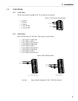
The terminals are as follows:
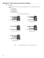
Figure 10: Analog Output Wiring Example
• 5) analog output
• 6) common
• 7) shield
See Also:
Analog Output Configurations (I/O 9 - 11 / P54 - 56) on Pages 77 and 78.
3.8.5 SW1
DIP
Switch
The SW1 DIP switch on the card allows selecting the analog input and output values of 0–10V or 0–20mA. The
picture below represents how to adjust the switch to select the desired signal.
Figure 11: SW1 DIP Switch Settings
ANALOG OUTPUT
SW1-2
ON = 0-10V
OFF = 0-20mA
ANALOG INPUT
SW1-1
ON = 0-20mA
OFF = 0-10V
V/I
TO METER / ANALOG INPUT CARD
+
-
TB5
Summary of Contents for RediStart MX2 SEP
Page 2: ......
Page 8: ...RediStart MX 2 SEP Synchronous Controller User Manual 8 ...
Page 14: ...RediStart MX 2 SEP Synchronous Controller User Manual 14 ...
Page 36: ...RediStart MX 2 SEP Synchronous Controller User Manual 36 ...
Page 52: ...RediStart MX 2 SEP Synchronous Controller User Manual 52 ...
Page 98: ...RediStart MX 2 SEP Synchronous Controller User Manual 98 ...
Page 114: ...RediStart MX 2 SEP Synchronous Controller User Manual 114 ...
Page 116: ...RediStart MX 2 SEP Synchronous Controller User Manual 116 ...
Page 118: ...RediStart MX 2 SEP Synchronous Controller User Manual 118 ...
Page 128: ...RediStart MX 2 SEP Synchronous Controller User Manual 128 ...
Page 129: ...Publication History Revision Date ECO 00 12 15 06 Initial Release 01 12 04 15 E4926 ...

