3 - Installation
21
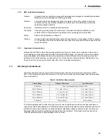
3.2.2 EMC
Installation
Guidelines
General
In order to help our customers comply with European electromagnetic compatibility standards,
Benshaw Inc. has developed the following guidelines.
Attention
This product has been designed for Class A equipment. Use of the product in domestic
environments may cause radio interference, in which case the installer may need to use
additional mitigation methods.
Enclosure
Install the product in a grounded metal enclosure.
Grounding
Connect a grounding conductor to the screw or terminal provided as standard on each
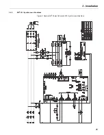
controller. Refer to layout/power wiring schematic for grounding provision location.
Wiring
Refer to Wiring Practices on Page 22.
Filtering
To comply with Conducted Emission Limits (CE requirement), a high voltage (1000V or greater)
0.1 uF capacitor should be connected from each input line to ground at the point where the line
enters the cabinet.
3.2.3
Application Considerations
Although the MX SEP controls and provides protection for the motor field current, protection of the motor’s
stator windings must be addressed separate from the MX SEP package. For example, if the motor is started
using a Benshaw motor starter, the overcurrent protection on the starter can be set to provide overcurrent
protection of the stator windings in cases such as the rotor puling out of synchronization. Additionally, a low
Power Factor trip can be used to detect when the rotor is no longer synchronized.
3.3
Mounting Considerations
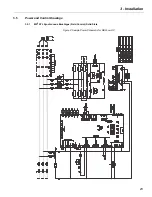
Provisions should be made to ensure that the temperature inside the enclosure never rises above 122
o
F /
50
o
C. If the temperature inside the enclosure is too high, the controller can be damaged, and the operational
life can be reduced.
The field supply produces 4 watts of heat per amp of current, and 26 square inches of enclosure surface is
required per watt of heat generation. Contact Benshaw and ask for the enclosure sizing technical note for more
information concerning controllers in sealed enclosures. Benshaw supplies controllers under 124 amps non-
bypassed, with the heat sink protruding from the back of the enclosure. This allows a small enclosure size,
while still maintaining the cooling capability of the controller.
Table 5: Ventilation Requirements
Current Range
Bottom of Enclosure
Top of Enclosure
< 200 amps
Fans or grills depending on enclosure size
200 to 300 amps
2 x 4” grills (12 sq. in.)
2 x 4” grills (12 sq.in.)
301 to 400 amps
1 x 4” fan (115 cfm)
2 x 4” grills (12 sq.in.)
401 to 600 amps
2 x 4” fan (230 cfm)
2 x 6” grills (28 sq.in.)
601 to 700 amps
2 x 6” fan (470 cfm)
2 x 6” grills (28 sq.in.)
> 700 amps
Consult Factory
Consult Factory
Summary of Contents for RediStart MX2 SEP
Page 2: ......
Page 8: ...RediStart MX 2 SEP Synchronous Controller User Manual 8 ...
Page 14: ...RediStart MX 2 SEP Synchronous Controller User Manual 14 ...
Page 36: ...RediStart MX 2 SEP Synchronous Controller User Manual 36 ...
Page 52: ...RediStart MX 2 SEP Synchronous Controller User Manual 52 ...
Page 98: ...RediStart MX 2 SEP Synchronous Controller User Manual 98 ...
Page 114: ...RediStart MX 2 SEP Synchronous Controller User Manual 114 ...
Page 116: ...RediStart MX 2 SEP Synchronous Controller User Manual 116 ...
Page 118: ...RediStart MX 2 SEP Synchronous Controller User Manual 118 ...
Page 128: ...RediStart MX 2 SEP Synchronous Controller User Manual 128 ...
Page 129: ...Publication History Revision Date ECO 00 12 15 06 Initial Release 01 12 04 15 E4926 ...


