background image

Version 7.2 

1065 

Mediant 500 MSBR 


User's Manual 


74. Configuration Parameters Reference 


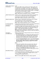
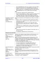
[TransparentCoderOnDat
aCall] 


[0] = (Default) Only use coders from the coder list. 


[1] = Use Transparent coder for data calls (according to RFC 4040). 

The Transparent coder can be used on data calls. When the device 
receives a Setup message from the ISDN with 'TransferCapabilities = 
data', it can initiate a call using the coder 'Transparent' (even if the 
coder is not included in the coder list). 

The initiated INVITE includes the following SDP attribute: 

a=rtpmap:97 CLEARMODE/8000


The default payload type is set according to the CodersGroup 
parameter. If the Transparent coder is not defined, the default is set to 
56. The payload type is negotiated with the remote side, i.e., the 
selected payload type is according to the remote side selection. The 
receiving device must include the 'Transparent' coder in its coder list. 

Note:

 The parameter is applicable only to digital interfaces. 

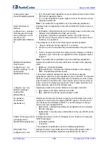
Network Node ID 

configure voip > sip-
definition settings > net-
node-id


[NetworkNodeId] 

Defines the Network Node Identifier of the device for Avaya UCID. 

The valid value range is1 to 0x7FFF. The default is 0. 

Note:


To use this feature, you must set the parameter to any value other 
than 0. 


To enable the generation by the device of the Avaya UCID value and 
adding it to the outgoing INVITE sent to the IP Group (Avaya entity), 
use the IP Groups table's parameter 'UUI Format'. 

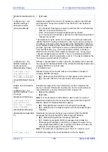
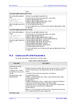
Default Release Cause 

configure voip > sip-
definition settings > dflt-
release-cse


[DefaultReleaseCause] 

Defines the default Release Cause (sent to IP) for IP-to-Tel calls when 
the device initiates a call release and an explicit matching cause for this 
release is not found.  

The default release cause is NO_ROUTE_TO_DESTINATION (3). 
Other common values include NO_CIRCUIT_AVAILABLE (34), 
DESTINATION_OUT_OF_ORDER (27), etc. 

Note:


The default release cause is described in the Q.931 notation and is 
translated to corresponding SIP 40x or 50x values (e.g., 3 to SIP 
404, and 34 to SIP 503). 


Analog: For more information on mapping PSTN release causes to 
SIP responses, see Mapping PSTN Release Cause to SIP 
Response on page 549. 


When the Trunk is disconnected or is not synchronized, the internal 
cause is 27. This cause is mapped, by default, to SIP 502. 


For mapping SIP-to-Q.931 and Q.931-to-SIP release causes, see 
Configuring Release Cause Mapping on page 541. 


For a list of SIP responses-Q.931 release cause mapping, see 
Alternative Routing to Trunk upon Q.931 Call Release Cause Code 
on page 518. 

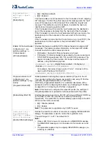
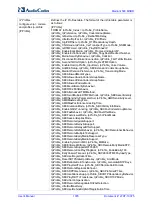
Enable Microsoft 
Extension 

configure voip > sip-
definition settings > 
microsoft-ext


[EnableMicrosoftExt] 

Enables the modification of the called and calling number for numbers 
received with Microsoft's proprietary "ext=xxx" parameter in the SIP 
INVITE URI user part. Microsoft Office Communications Server 
sometimes uses this proprietary parameter to indicate the extension 
number of the called or calling party.  


[0]

 Disable (default) 


[1]

 Enable 

For example, if a calling party makes a call to telephone number 
622125519100 Ext. 104, the device receives the SIP INVITE (from 

Summary of Contents for Mediant 500 MSBR

Page 1: ...User s Manual AudioCodes Family of Multi Service Business Routers MSBR Mediant 500 MSBR Version 7 2 ...

Page 2: ......

Page 3: ...S Management 43 5 2 Remote Telnet or SSH Management 43 Management Tools 45 6 Introduction 47 7 Web Based Management 49 7 1 Getting Acquainted with the Web Interface 49 7 1 1 Computer Requirements 49 7 1 2 Accessing the Web Interface 50 7 1 3 Areas of the GUI 51 7 1 4 Accessing Configuration Pages from Navigation Tree 52 7 1 5 Configuring Stand alone Parameters 54 7 1 6 Configuring Table Parameters...

Page 4: ...2 Enabling SSH with RSA Public Key for CLI 84 8 2 Configuring Maximum Telnet SSH Sessions 87 8 3 Establishing a CLI Session 87 8 4 Viewing Current CLI Sessions 88 8 5 Terminating a User s CLI Session 88 8 6 Configuring Displayed Output Lines in CLI Terminal Window 89 8 7 Configuring TACACS for CLI Login 89 9 SNMP Based Management 91 9 1 Disabling SNMP 91 9 2 Configuring SNMP Community Strings 91 9...

Page 5: ...xpiry Check 130 14 Date and Time 133 14 1 Configuring Automatic Date and Time using SNTP 133 14 2 Configuring Date and Time Manually 134 14 3 Configuring the Time Zone 134 14 4 Configuring Daylight Saving Time 135 General VoIP Configuration 137 15 Network 139 15 1 Viewing Network Configuration 139 15 2 Network Address Translation Support 140 15 2 1 Device Located behind NAT 140 15 2 1 1 Configurin...

Page 6: ... 1 Modem Relay 178 17 2 5 Simultaneous Negotiation of Fax T 38 and Modem V 150 1 Relay 179 17 2 6 V 152 Support 179 17 3 Configuring RTP RTCP Settings 180 17 3 1 Configuring the Dynamic Jitter Buffer 180 17 3 2 Comfort Noise Generation 181 17 3 3 Configuring DTMF Transport Types 181 17 3 4 Configuring RFC 2833 Payload 183 17 3 5 Configuring RTP Base UDP Port 183 17 4 Event Detection and Notificati...

Page 7: ...for Numbers with Characters 238 18 3 12 AD based Routing for Microsoft Skype for Business 238 18 3 12 1Querying the AD and Routing Priority 238 18 3 12 2Configuring AD Based Routing Rules 241 18 3 12 3Querying the AD for Calling Name 244 18 4 Least Cost Routing 245 18 4 1 Overview 245 18 4 2 Configuring LCR 247 18 4 2 1 Configuring Cost Groups 248 18 4 2 2 Assigning Cost Groups to Routing Rules 25...

Page 8: ...nd SEM 292 19 1 3 Enabling RTCP XR Reporting to SEM 292 19 2 Configuring Quality of Experience Profiles 293 19 3 Configuring Bandwidth Profiles 298 19 4 Configuring Quality of Service Rules 302 20 Control Network 307 20 1 Configuring Media Realms 307 20 1 1 Configuring Remote Media Subnets 310 20 1 2 Configuring Media Realm Extensions 313 20 2 Configuring SRDs 315 20 2 1 Filtering Tables in Web In...

Page 9: ...s 465 25 4 Configuring Digital Gateway Parameters 467 25 5 Tunneling Applications 468 25 5 1 TDM Tunneling 468 25 5 1 1 DSP Pattern Detector 471 25 5 2 Configuring Private Wire Interworking 471 25 5 3 QSIG Tunneling 476 25 6 ISDN Non Facility Associated Signaling NFAS 477 25 6 1 NFAS Interface ID 478 25 6 2 Working with DMS 100 Switches 479 25 6 3 Creating an NFAS Related Trunk Configuration 479 2...

Page 10: ...ing 541 28 8 1 1 Configuring SIP to ISDN Release Cause Mapping 541 28 8 1 2 Fixed Mapping of SIP Response to ISDN Release Reason 542 28 8 2 ISDN to SIP Release Cause Mapping 544 28 8 2 1 Configuring ISDN to SIP Release Cause Mapping 544 28 8 2 2 Fixed Mapping of ISDN Release Reason to SIP Response 545 28 8 3 Configuring ISDN to ISDN Release Cause Mapping 547 28 8 4 Reason Header 549 28 8 5 Mapping...

Page 11: ...es 587 30 15Detecting Collect Calls 591 30 16Advice of Charge Services for Euro ISDN 592 30 17Configuring Charge Codes 593 30 18Configuring Voice Mail 595 30 19Converting Accented Characters from IP to Tel 597 31 Analog Gateway 599 31 1 Configuring Keypad Features 599 31 2 Configuring Metering Tones 600 31 3 Configuring FXO Settings 600 31 4 Configuring Authentication 601 31 5 Configuring Automati...

Page 12: ...Restricting Audio Coders 640 32 5 4 Prioritizing Coder List in SDP Offer 641 32 5 5 Multiple RTP Media Streams per Call Session 641 32 5 6 Interworking Miscellaneous Media Handling 641 32 5 6 1 Interworking RTP Redundancy 642 32 5 6 2 Interworking RTP RTCP Multiplexing 642 32 5 6 3 Interworking RTCP Attribute in SDP 642 32 5 6 4 Interworking Crypto Lifetime Field 642 32 5 6 5 Interworking Media Se...

Page 13: ...figuring SBC Routing Policy Rules 692 37 5 Configuring IP Group Sets 695 38 SBC Manipulations 699 38 1 Configuring IP to IP Inbound Manipulations 701 38 2 Configuring IP to IP Outbound Manipulations 705 39 Configuring Dial Plans 711 39 1 Importing and Exporting Dial Plans 715 39 2 Creating Dial Plan Files 718 39 3 Using Dial Plan Tags for IP to IP Routing 719 39 3 1 Using Dial Plan Tags for Matchi...

Page 14: ... Mode 748 43 4 2 Emergency Mode 749 43 4 3 Auto Answer to Registrations 749 43 5 Configuring PSTN Fallback 750 Data Router Configuration 751 44 Introduction 755 Maintenance 757 45 Basic Maintenance 759 45 1 Resetting the Device 759 45 2 Remotely Resetting Device using SIP NOTIFY 760 45 3 Locking and Unlocking the Device 760 45 4 Saving Configuration 761 46 Channel Maintenance 763 46 1 Disabling An...

Page 15: ...Sensitivity File 795 49 License Key 797 49 1 Viewing the License Key 797 49 2 Installing a New License Key 798 49 2 1 Installing License Key through Web Interface 798 49 2 1 1 Installing a License Key String 798 49 2 1 2 Installing a License Key File 800 49 2 2 Installing License Key through CLI 802 49 2 3 Verifying Installed License Key 802 49 3 Upgrading SBC Capacity Licenses by License Pool Man...

Page 16: ...through Web Interface 835 53 3 Restoring Defaults using Hardware Reset Button 836 53 4 Restoring Defaults through ini File 836 Status Performance Monitoring and Reporting 837 54 System Status 839 54 1 Viewing Device Information 839 54 2 Viewing Device Status on Monitor Page 840 54 2 1 Viewing Voice Port Information 843 55 Viewing Carrier Grade Alarms 849 55 1 Viewing Active Alarms 849 55 2 Viewing...

Page 17: ...ing a USB Flash Drive 925 Diagnostics 927 63 Syslog and Debug Recording 929 63 1 Configuring Log Filter Rules 929 63 1 1 Filtering IP Network Traces 933 63 2 Configuring Syslog 934 63 2 1 Syslog Message Format 934 63 2 1 1 Event Representation in Syslog Messages 937 63 2 1 2 Unique Device Identification in Syslog Messages 938 63 2 1 3 Identifying AudioCodes Syslog Messages using Facility Levels 93...

Page 18: ...dress 973 72 Troubleshooting using a USB Flash Drive 975 Appendix 977 73 Dialing Plan Notation for Routing and Manipulation 979 74 Configuration Parameters Reference 983 74 1 Management Parameters 983 74 1 1 General Parameters 983 74 1 2 Web Parameters 985 74 1 3 Telnet Parameters 989 74 1 4 ini File Parameters 990 74 1 5 SNMP Parameters 990 74 1 6 TR 069 Parameters 994 74 1 7 Serial Parameters 99...

Page 19: ... Collection and Dial Plan Parameters 1099 74 10 4 Voice Mail Parameters 1101 74 10 5 Supplementary Services Parameters 1107 74 10 5 1Caller ID Parameters 1107 74 10 5 2Call Waiting Parameters 1112 74 10 5 3Call Forwarding Parameters 1114 74 10 5 4Message Waiting Indication Parameters 1116 74 10 5 5Call Hold Parameters 1118 74 10 5 6Call Transfer Parameters 1119 74 10 5 7Multi Line Extensions and S...

Page 20: ...12 1 Supplementary Services 1226 74 13IP Media Parameters 1226 74 14Services 1231 74 14 1 SIP based Media Recording Parameters 1231 74 14 2 RADIUS and LDAP Parameters 1232 74 14 2 1General Parameters 1232 74 14 2 2RADIUS Parameters 1233 74 14 2 3LDAP Parameters 1235 74 14 3 Least Cost Routing Parameters 1238 74 14 4 Call Setup Rules Parameters 1238 74 14 5 HTTP based Services 1239 74 14 6 HTTP Pro...

Page 21: ... at http www audiocodes com downloads This document is subject to change without notice Date Published August 10 2017 WEEE EU Directive Pursuant to the WEEE EU Directive electronic and electrical waste must not be disposed of with unsorted waste Please contact your local recycling authority for disposal of this product Customer Support Customer technical support and services are provided by AudioC...

Page 22: ... s security policies For basic security guidelines refer to AudioCodes Recommended Security Guidelines document Note Throughout this manual unless otherwise specified the term device refers to your AudioCodes product Note Before configuring the device ensure that it is installed correctly as instructed in the Hardware Installation Manual Note The device s installed License Key does not include the...

Page 23: ...e consult your AudioCodes sales representative Note OPEN SOURCE SOFTWARE Portions of the software may be open source software and may be governed by and distributed under open source licenses such as the terms of the GNU General Public License GPL the terms of the Lesser General Public License LGPL BSD and LDAP which terms are located at http www audiocodes com support and all are incorporated her...

Page 24: ...ing Specific UDP Ports using Tag based Routing Updated parameters WebUsers_Password note ProxySet_SuccessDetectionRetries max ProxySet_SuccessDetectionInterval max Account_RegistrarSearchMode phys link AudioCoders_Sce global parameter removed IpProfile_SCE removed IpProfile_SBCRemoteReferBehavior new option 5 IPProfile_SBCRemoteHoldFormat new option 6 SBCCDRFormat_Title max char WebUsers CLI name ...

Page 25: ...ved by a centralized SIP based IP Centrex server or branch offices of distributed enterprises Call survivability enables internal office communication between SIP clients in the case of disconnection from the centralized SIP IP Centrex server or IP PBX The device supports the following interfaces Multiple WAN Single Gigabit Ethernet copper 10 100 1000Base T unshielded twisted pair UTP interface po...

Page 26: ... parameter values Navigational path Click the Add button Text enclosed by double apostrophe Parameter value that you need to type In the IP Address field enter 10 10 1 1 Courier font CLI commands At the prompt type the following configure system Text enclosed by square brackets Ini file parameters and values Configure the GWDebugLevel parameter to 1 Text enclosed by single apostrophe Web interface...

Page 27: ... IP network interface The term local implies that it s a logical port and network interface on the device The SIP Interface is used to receive and send SIP messages with a specific SIP entity IP Group Therefore you can create a SIP Interface for each SIP entity in the VoIP network with which your device needs to communicate For example if your VoIP network consists of three SIP entities a SIP Trun...

Page 28: ...if the source IP address is defined for a Proxy Set and if yes it classifies it to the IP Group associated with the Proxy Set If this fails the device classifies the SIP dialog using the Classification table which defines various characteristics of the incoming dialog that if matched classifies the call to a specific IP Group The main characteristics of the incoming call is the SIP Interface that ...

Page 29: ...y is required When only a single Routing Policy is required handling of this configuration entity is not required as a default Routing Policy is provided which is automatically associated with all relevant configuration entities Call Admission Control Call Admission Control CAC lets you configure the maximum number of permitted concurrent calls SIP dialogs per IP Group SIP Interface SRD or user Ac...

Page 30: ...n be applied to the outgoing dialog 1 3 2 Gateway Application The objective of your configuration is to enable the device to forward calls between the IP based endpoints and PSTN based endpoints The PSTN based endpoints can be analog endpoints such as FXO e g PBX or FXS plain old telephone service or POTS or digital endpoints such as ISDN trunks The IP based endpoints SIP entities can be servers s...

Page 31: ...cally only a single SRD is required and this is the recommended configuration topology As the device provides a default SRD in a single SRD topology the device automatically assigns the SRD to newly created configuration entities Thus in such scenarios there is no need to get involved with SRD configuration Multiple SRDs are required only for multi tenant deployments IP Profiles The IP Profile is ...

Page 32: ...the PSTN based endpoint Authentication SIP 401 is typically relevant for INVITE messages forwarded by the device to a SIP entity Registration is for REGISTER messages which are initiated by the device on behalf of the PSTN based endpoint The following figure shows the main configuration entities and their involvement in call processing The figure is used only as an example to provide basic underst...

Page 33: ...Part I Getting Started with Initial Connectivity ...

Page 34: ......

Page 35: ... Introduction 2 Introduction This part describes how to initially access the device s management interface and change its default IP address to correspond with your networking scheme Device management can be done though the LAN and or WAN interface ...

Page 36: ...User s Manual 36 Document LTRT 10375 Mediant 500 MSBR This page is intentionally left blank ...

Page 37: ...port located on the front panel to the serial communication port on your computer For more information refer to the Hardware Installation Manual 2 Establish serial communication with the device using a terminal emulator program such as HyperTerminal or putty with the following communication port settings Baud Rate 115 200 bps Data Bits 8 Parity None Stop Bits 1 Flow Control None Figure 3 1 Example...

Page 38: ...e LAN and with default IP pool addresses relating to the default subnet LAN The DHCP server allocates this pool of IP addresses to computers connected to its LAN interface You can disable the DHCP server or modify the IP address pool see Configuring the Device s DHCP Server on page 41 To access the device using the default LAN IP Address 1 Connect LAN Port 1 left most port located on the front pan...

Page 39: ...mputer start a Web browser and in the URL address field enter the device s default IP address see table above the Web interface s Web Login screen appears Figure 3 3 Web Login Screen 4 In the Username and Password fields enter the case sensitive default login username Admin and password Admin 5 Click Login ...

Page 40: ...User s Manual 40 Document LTRT 10375 Mediant 500 MSBR This page is intentionally left blank ...

Page 41: ...ng command to access the router configuration mode configure data 3 Access the VLAN 1 LAN switch interface config data interface vlan 1 4 Configure the IP address and subnet conf if VLAN 1 ip address IP address subnet For example conf if VLAN 1 ip address 10 8 6 85 255 255 255 0 5 Save your settings with a flash burn conf if VLAN 1 do write 4 2 Configuring the Device s DHCP Server By default the d...

Page 42: ...ur Internet Telephony Service Provider ITSP To configure a WAN IP address 1 Connect the WAN port to the WAN network For information on cabling the WAN port refer to the Hardware Installation Manual 2 Establish serial communication with the device 3 At the prompt type the following command to access the router configuration mode configure data 4 Access the WAN interface config data interface Gigabi...

Page 43: ...anagement from the WAN config system web web wan https allow on web exit config system exit Web 1 Open the Web Settings page Setup menu Administration tab Web CLI folder Web Settings 2 From the Allow WAN access to HTTPS or Allow WAN access to HTTP drop down list select Enable Figure 5 1 Enabling Remote Management through WAN HTTP S Port 3 Click Apply and then click Save 5 2 Remote Telnet or SSH Ma...

Page 44: ...gs ssh on 4 Enable SSH from WAN cli settings wan ssh allow on 5 Save configuration to flash cli settings do write Web 1 Open the CLI Settings page Setup menu Administration tab Web CLI folder CLI Settings 2 For Telnet From the Allow WAN access to Telnet drop down list select Enable Figure 5 2 Enabling Telnet from WAN 3 For SSH From the Enable SSH Server drop down list select Enable Figure 5 3 Enab...

Page 45: ...Part II Management Tools ...

Page 46: ......

Page 47: ...nd Line Interface CLI see CLI Based Management on page 83 Simple Network Management Protocol SNMP see SNMP Based Management on page 91 TR 069 see TR 069 Based Management on page 99 Configuration ini file see INI File Based Management on page 107 Note Some configuration settings can only be done using a specific management tool For a list and description of all the configuration parameters see Conf...

Page 48: ...User s Manual 48 Document LTRT 10375 Mediant 500 MSBR This page is intentionally left blank ...

Page 49: ...ges and limiting access to specific IP addresses Note The Web interface allows you to configure most of the device s settings However additional configuration parameters may exist that are not available in the Web interface and which can only be configured using other management tools Some Web interface pages and or parameters are available only for certain hardware configurations or software feat...

Page 50: ...itive To change the login credentials see Configuring Management User Accounts on page 71 By default autocompletion of the login username is enabled whereby the Username field offers previously entered usernames To disable autocompletion use the WebLoginBlockAutoComplete ini file parameter Depending on your Web browser s settings a security warning box may be displayed The reason for this is that ...

Page 51: ...r settings to flash memory by clicking the button Reset Opens the Maintenance Actions page which is used for performing various maintenance procedures such as resetting the device see Basic Maintenance on page 759 If you make a configuration change that takes effect only after a device reset the button is surrounded by a red colored border as a reminder to save your settings to flash memory with a...

Page 52: ...previously accessed page Forward button Opens the page that you initially left using the back button The button is available only if you have used the Back button 8 Navigation pane which displays the Navigation tree containing the commands items for opening the configuration pages see Navigation Tree on page 52 9 SRD filter When your configuration includes multiple SRDs you can filter tables in th...

Page 53: ...containing commonly required items are opened by default allowing quick access to their pages Items that open pages containing tables provide the following indications in the Navigation tree Number of configured rows For example the item below indicates that two rows have been configured If you have filtered the Web interface display by SRD the number reflects only the rows that are associated wit...

Page 54: ...ng until you reach any other previously accessed page Forward button Click to open the page that you just left as a result of clicking the Back button These buttons are especially useful when you find that you need to return to a previously accessed page and then need to go back to the page you just left Note Depending on the access level e g Monitor level of your Web user account certain pages ma...

Page 55: ...re stand alone parameters To configure a stand alone parameter 1 Modify the parameter s value as desired 2 Click Apply the changes are saved to the device s volatile memory RAM 3 Save the changes to the device s non volatile memory flash If a device reset is not required a On the toolbar click Save a confirmation message box appears Figure 7 4 Save Configuration Confirmation Box b Click Yes to con...

Page 56: ...e see Adding Table Rows on page 57 Modifies the selected row see Modifying Table Rows on page 59 Adds a new row with similar settings as the selected row i e clones the row For more information see Cloning SRDs on page 324 Note The button appears only in the SRDs table Deletes the selected row see Deleting Table Rows on page 59 Changes the index position of a selected row see Changing Index Positi...

Page 57: ...lbar a dialog box appears 2 Configure the parameters of the row as desired For information on configuring parameters that are assigned a value which is a row referenced from another table see Assigning Rows from Other Tables on page 57 3 Click Apply to add the row to the table or click Cancel to ignore your configuration 4 If the Save button is surrounded by a red border you must save your setting...

Page 58: ... this step c Select the desired row in the row referenced table and then click Use selected row located on the top right of the table as shown in the example below Figure 7 8 Selecting Referenced Row Adding a new referenced row a From the drop down list select the Add new option as shown in the example below Figure 7 9 Selecting Add new Option The table e g IP Groups table and dialog box in which ...

Page 59: ...our new settings are applied 4 If the Save button is surrounded by a red border you must save your settings to flash memory otherwise they are discarded if the device resets without a save to flash or powers off 7 1 6 4 Deleting Table Rows The following procedure describes how to delete a row from a table To delete a table row 1 Select the row that you want to delete 2 Click the delete icon locate...

Page 60: ...ick Apply an error message is displayed at the bottom of the dialog box If you click Cancel the dialog box closes and the row is not added to the table For example if you do not configure the SIP Interface field mandatory for a Proxy Set in the Proxy Sets table the below message appears Editing a row If you modify the parameter so that it s no longer referencing a row of another table i e blank va...

Page 61: ...d reference line see description above the Invalid Reference Line icon appears along side it For example when configuring an IP Group the Proxy Set parameter s drop down list displays items Proxy Set 0 with indicating that it has an invalid parameter value and Proxy Set 1 with indicating that it has a parameter that is referenced to a row of another table that has an invalid value Figure 7 13 Inva...

Page 62: ...e next table page Displays the last table page i e page with last index row 3 Currently displayed table page To open a specific table page enter the page number and then press the Enter key 4 Total number of table pages 7 1 6 7 Sorting Tables by Column You can sort table rows by any column and in ascending order e g 1 2 and 3 a b and c or descending order e g 3 2 and 1 c b and a By default most ta...

Page 63: ...n on page 62 Changing row position is supported only by certain tables e g IP to IP Routing table To change the position of a row 1 Click the Index column header so that the rows are sorted in ascending order e g 0 1 2 and so on 2 Select the row that you want to move 3 Do one of the following To move one index up e g from Index 3 to 2 Click the up arrow the row moves one index up in the table e g ...

Page 64: ...h you want to search 3 Click the magnifying glass icon to run the search If the device finds the value the table displays only the rows in which the value was found You can then select any row and modify it by clicking the Edit button If the search is unsuccessful no rows are displayed 4 To quit the Search tool and continue configuring rows click the icon located in the Search box 7 1 7 Searching ...

Page 65: ...es The use of other characters are invalid To search for a parameter 1 In the search box enter the search key parameter name or value 2 Click the search icon the Search Result window appears listing found parameters based on your search key Each searched result displays the following Navigation path link to the page on which the parameter appears Parameter s name Parameter s value Brief descriptio...

Page 66: ... the Web Login window appears enabling you to re login if required 7 2 Customizing the Web Interface You can customize the following elements of the device s Web interface GUI Corporate logo see Replacing the Corporate Logo on page 67 Device s product name see Customizing the Product Name on page 69 Favicon see Customizing the Favicon on page 70 Login welcome message see Creating a Login Welcome M...

Page 67: ...ollowing A different image see Replacing the Corporate Logo with an Image on page 67 Text see Replacing the Corporate Logo with Text on page 68 7 2 1 1 Replacing the Corporate Logo with an Image You can replace the logo with a different image The following figure displays an example where the default logo top is replaced with a different image bottom Figure 7 22 Customizing Web Logo Image To custo...

Page 68: ...ings to take effect Note The logo image file type can be GIF PNG JPG or JPEG The logo image must have a fixed height of 24 pixels The width can be up to 199 pixels default is 145 The maximum size of the image file can be 64 Kbytes Ignore the ini Parameters option which is located on the left pane of the Admin page 7 2 1 2 Replacing the Corporate Logo with Text You can replace the logo with text Th...

Page 69: ...oduct Name Web Login screen Figure 7 25 Customizing Product Name Example Ini file Board field Board My Product Name CLI prompt My Product Name config system To customize the device s product name 1 Create an ini file that includes the following parameter settings UseProductName 1 UserProductName name 2 Load the ini file using the Auxiliary Files page see Loading Auxiliary Files on page 771 3 Reset...

Page 70: ... URL address field append the case sensitive suffix AdminPage to the device s IP address e g http 10 1 229 17 AdminPage 3 Log in with your credentials the Admin page appears 4 On the left pane click Image Load to Device the right pane displays the following Figure 7 27 Customizing Favicon 5 Use the Browse button to select your favicon file and then click Send File the device loads the image file 6...

Page 71: ...ine in your message for example WelcomeMessage FORMAT WelcomeMessage_Index WelcomeMessage_Text WelcomeMessage 1 WelcomeMessage 2 This is a Welcome message WelcomeMessage 3 WelcomeMessage 2 Load the ini file using the Auxiliary Files page see Loading Auxiliary Files on page 771 3 Reset the device with a save to flash for your settings to take effect To remove the welcome message 1 Load an empty ini...

Page 72: ...he last Security Administrator Note Only Master users can delete Master users If only one Master user exists it can be deleted only by itself Administrator 100 Read write privileges for all Web pages except security related pages and the Local Users table where this user has read only privileges Monitor 50 Read only privileges and access to security related pages is blocked Note Only Security Admi...

Page 73: ...regardless of Web user access levels using the ini file parameter DisableWebConfig see Web and Telnet Parameters on page 983 You can define additional Web user accounts using a RADIUS server see RADIUS Authentication on page 212 The following procedure describes how to configure user accounts through the Web interface You can also configure it through ini file WebUsers or CLI configure system user...

Page 74: ... Web interface and ini File In the Web interface they are displayed as dots when you enter the password and then once applied the password is displayed as an asterisk in the table In the ini file they are displayed as an encrypted string User Level privilege WebUsers_UserLevel Defines the user s access level Monitor Default Read only user This user can only view Web pages and access to security re...

Page 75: ...eed a user defined number of failed login attempts set by the Deny Access on Fail Count parameter see Configuring Web Session and Access Settings on page 77 These users can log in only after a user defined timeout configured by the Block Duration parameter see below or if their status is changed to New or Valid by a Security Administrator or Master Inactivity The state is automatically set for use...

Page 76: ...or the configured timeout duration The valid value is 0 to 100000 A value of 0 means no timeout The default value is according to the settings of the WebSessionTimeout global parameter see Configuring Web Session and Access Settings on page 77 Block Duration block duration WebUsers_BlockTime Defines the duration in seconds for which the user is blocked when the user exceeds a user defined number o...

Page 77: ...rmation The following information is displayed Access Level User level of the currently logged in user e g Security Administrator Session Time Duration of the current Web session starting from login The Log Out button is also provided for logging out of the Web session see Logging Off the Web Interface on page 66 7 6 Configuring Web Session and Access Settings The following procedure describes how...

Page 78: ...ccounts on page 71 Session Timeout Duration in minutes of inactivity i e no actions are performed in the Web interface of a logged in user after which the Web session expires and the user is automatically logged off the Web interface and needs to log in again to continue the session You can also configure the functionality per user in the Local Users table see Configuring Management User Accounts ...

Page 79: ... Current Password field type in your current login password 3 In the New Password field type in your new password 4 In the Confirm New Password field type in your new password again 5 Click Change you are logged off the Web session and prompted to login in again with your new login password 7 8 Configuring Secured HTTPS Web By default the device allows remote management client through HTTP and HTT...

Page 80: ...ing VRF To limit OAMP access on a specific WAN interface through CLI 1 Enable WAN management access for specific OAMP applications using any of the following commands config system cli terminal cli terminal wan ssh allow wan telnet allow wan snmp allow wan http allow wan https allow 2 Define the WAN interface for the OAMP applications using the OAMPWanInterfaceName ini file parameter or the follow...

Page 81: ...cess the device using the following URL https host name or IP address the device prompts for a username and password 3 Enter the password only As some browsers require that the username be provided it s recommended to enter the username with an arbitrary value 7 11 Configuring Web and Telnet Access List The Access List table lets you restrict access to the device s management interfaces Web Telnet...

Page 82: ...ve configured IP addresses in the Access List and you no longer want to restrict access to the management interface based on the Access List delete all the IP addresses in the table as described in the following procedure Note When deleting all the IP addresses make sure that you delete the IP address of the computer from which you are currently logged into the device last otherwise access from yo...

Page 83: ...cribes how to enable Telnet You can enable a secured Telnet that uses Secure Socket Layer SSL where information is not transmitted in clear text If SSL is used a special Telnet client is required on your PC to connect to the Telnet interface over a secured connection examples include C Kermit for UNIX and Kermit 95 for Windows For security some organizations require the display of a proprietary no...

Page 84: ...ires appropriate client software for the management PC Most Linux distributions have OpenSSH pre installed Windows based PCs require an SSH client software such as PuTTY which can be downloaded from http www chiark greenend org uk sgtatham putty By default SSH uses the same username and password as the device s Telnet and Web server SSH supports 1024 2048 bit RSA public keys providing carrier grad...

Page 85: ...ow Figure 8 2 Selecting Public RSA Key in PuTTY 2 You can use the public key per management user or for all management users Per user Open the Local Users table see Configuring Management User Accounts on page 71 and then for the required user paste the public key that you copied in Step 1 d into the SSH Public Key field as shown below Figure 8 3 Pasting Public RSA Key per User in Local Users Tabl...

Page 86: ...tegory tree drill down to Connection then SSH and then Auth the Options controlling SSH authentication pane appears b Under the Authentication parameters group click Browse and then locate the private key file that you created and saved in Step 4 5 Connect to the device with SSH using the username Admin RSA key negotiation occurs automatically and no password is required To configure RSA public ke...

Page 87: ...ablishing a CLI Session You can access the device s CLI using any of the following methods RS 232 The device can be accessed through its RS 232 serial port by connecting a VT100 terminal to it or using a terminal emulation program e g HyperTerminal with a PC For connecting to the CLI through RS 232 see CLI Secure SHell SSH The device can be accessed through its Ethernet interface by the SSH protoc...

Page 88: ...ime of the session Each user is displayed with a unique index session ID To view currently logged in CLI users 1 Establish a CLI session with the device 2 Run the following command show users 0 console Admin local 0d00h03m15s 1 telnet John 10 4 2 1 0d01h03m47s 2 ssh Alex 192 168 121 234 12d00h02m34s The current session from which this show command was run is displayed with an asterisk Note The dev...

Page 89: ... length the MORE prompt is not displayed To configure the number of displayed output lines by dragging terminal window 1 Establish a CLI session with the device 2 Access the System menu configure system 3 At the prompt type the following command config system cli terminal 4 At the prompt type the following command cli terminal window height automatic When this mode is configured each time you chan...

Page 90: ... is authenticated and service may begin If the network access server is configured to require authorization authorization will begin at this time REJECT The user has failed to authenticate The user may be denied further access ERROR An error occurred at some time during authentication This can be at the daemon or in the network connection between the daemon and the network access server If an ERRO...

Page 91: ... 9 1 Disabling SNMP By default SNMP is enabled However you can disable it as described in the following procedure To disable SNMP 1 Open the SNMP Community Settings page Setup menu Administration tab SNMP folder SNMP Community Settings 2 From the Disable SNMP drop down list DisableSNMP parameter select Yes Figure 9 1 Disabling SNMP 3 Click Apply 9 2 Configuring SNMP Community Strings SNMP communit...

Page 92: ...y string the source and or destination address of the packet received from the management station and in which the community string is received can be specified This adds enhanced security by reducing the likelihood of malicious attacks on the device if the community string is discovered by an attacker To assign an ACL rule use the following CLI command config system snmp snmp snmp acl community s...

Page 93: ...P community strings Up to five read only community strings can be configured The valid value is a string of up to 30 characters that can include only the following Upper and lower case letters a to z and A to Z Numbers 0 to 9 Hyphen Underline _ For example Public comm_string1 The default is public Read Write Community Strings configure system snmp settings rw community string SNMPReadWriteCommunit...

Page 94: ...Select the check boxes corresponding to the configured SNMP managers that you want to enable 4 Click Apply Note Rows whose corresponding check boxes are cleared revert to default settings when you click Apply To enable the sending of the trap event acPerformanceMonitoringThresholdCrossing which is sent every time a threshold high or low of a performance monitored SNMP object is crossed configure t...

Page 95: ...le and the last trap manager entry in the snmpTargetAddrTable in the snmpTargetMIB Note If you configure an FQDN for an SNMP trap manager The device ignores your configuration in the SNMP Trap Destinations table Only one SNMP trap manager can be configured To configure an SNMP trap destination with an FQDN 1 Open the SNMP Community Settings page Setup menu Administration tab SNMP folder SNMP Commu...

Page 96: ...activities that you want reported see Configuring Reporting of Management User Activities on page 941 To enable traps to SNMP manager for Web activity 1 Open the SNMP Community Settings page Setup menu Administration tab SNMP folder SNMP Community Settings 2 Under the Misc Settings group from the Activity Trap drop down list EnableActivityTrap select Enable Figure 9 5 Enabling Trap for Web User Ac...

Page 97: ...for your settings to take effect Table 9 3 SNMPv3 Users Table Parameters Description Parameter Description Index SNMPUsers_Index Defines an index number for the new table row Note Each row must be configured with a unique index User Name username SNMPUsers_Username Name of the SNMP v3 user The name must be unique Authentication Protocol auth protocol SNMPUsers_AuthProtocol Authentication protocol ...

Page 98: ... persisted as long hex strings and keys are localized Privacy Key priv key SNMPUsers_PrivKey Privacy key Keys can be entered in the form of a text password or long hex string Keys are always persisted as long hex strings and keys are localized Group group SNMPUsers_Group The group with which the SNMP v3 user is associated 0 Read Only 1 Read Write default 2 Trap Note All groups can be used to send ...

Page 99: ...69 Technical Report 069 is a specification published by Broadband Forum www broadband forum org entitled CPE WAN Management Protocol CWMP It defines an application layer protocol for remote management of end user devices TR 069 uses a bi directional SOAP HTTP protocol for communication between the customer premises equipment CPE and the Auto Configuration Servers ACS The TR 069 connection to the A...

Page 100: ...ote Procedure Call RPC methods TR 069 defines a generic mechanism by which an ACS can read or write parameters to configure a CPE and monitor CPE status and statistics It also defines the mechanism for file transfer and firmware software management However it does not define individual parameters these are defined in separate documents as described below Some of the RPC methods are Configuration F...

Page 101: ...ith SetParameterValues Used by the ACS to modify the value of CPE parameter s GetParameterValues Used by the ACS to obtain the value of CPE parameter s GetParameterNames Used by the ACS to discover the parameters accessible on a particular CPE SetParameterAttributes Used by the ACS to modify attributes associated with CPE parameter s GetParameterAttributes Used by the ACS to read the attributes as...

Page 102: ... session as the Download request indicating either success or failure In this case the Status argument in the corresponding DownloadResponse has a value of one A TransferComplete message sent in a subsequent session indicating success or failure In this case the Status argument in the corresponding DownloadResponse has a value of one Figure 10 3 Download Method Executuion Example Upload Used by th...

Page 103: ...ssful completion via the UploadResponse or TransferComplete method For a complete description of the Upload method refer to TR 069 Amendment 3 section A 4 1 5 Reboot Reboots the CPE The CPE sends the method response and completes the remainder of the session prior to rebooting X_0090F8_CommandResponse Runs CLI commands ACS Methods Inform A CPE must call this method to initiate a transaction sequen...

Page 104: ...ternetGatewayDevice Services VoiceService 1 Capabilities Read Only Displays the overall capabilities of the device InternetGatewayDevice Services VoiceService 1 Capabilities Codecs Read Only Lists supported codecs according to devices installed License Key InternetGatewayDevice Services VoiceService 1 Capabilities SIP Read Only Displays various SIP settings such as SIP transport type InternetGatew...

Page 105: ...er ID InternetGatewayDevice Services VoiceService 1 VoiceProfile 1 Line i SIP Configures username password per FXS line AudioCodes maps this object to the corresponding entry in the Authentication table InternetGatewayDevice Services VoiceService 1 VoiceProfile 1 SIP Configures SIP parameters specific to the UA such as Proxy server InternetGatewayDevice Services VoiceService 1 VoiceProfile 1 RTP C...

Page 106: ...R 069 To configure TR 069 1 Open the CWMP TR 069 Settings page Setup menu IP Network tab TR 069 CWMP Figure 10 5 CWMP TR 069 Settings Page 2 Configure the parameters as required For a description of the TR 069 parameters see TR 069 Parameters on page 994 3 Click Apply 4 To save the changes to flash memory see Saving Configuration on page 761 ...

Page 107: ...l sign and then its value Comments must be preceded by a semicolon optional subsection name parameter name value parameter name value this is a comment line for example System Parameters SyslogServerIP 10 13 2 69 EnableSyslog 1 For general ini file formatting rules see General ini File Formatting Rules on page 109 11 1 2 Configuring Table ini File Parameters Table ini file parameters allow you to ...

Page 108: ...lines are interpreted according to the order specified in the Format line The double dollar sign in a Data line indicates the default value for the parameter The order of the Data lines is insignificant Data lines must match the Format line i e it must contain exactly the same number of Indices and Data fields and must be in exactly the same order A row in a table is identified by its table name a...

Page 109: ...riage return 11 2 Configuring an ini File There are different methods that you can use for configuring an ini file before you load it to the device Modifying the device s current ini file This method is recommended if you mainly need to change the settings of parameters that you have previously configured 1 Save the device s current configuration as an ini file on your computer using the Web inter...

Page 110: ...oaded to the device using HTTP These protocols are not secure and are vulnerable to potential hackers To overcome this security threat the AudioCodes DConvert utility allows you to binary encode encrypt the ini file before loading it to the device For more information refer to the DConvert Utility User s Guide Note If you save an ini file from the device to a folder on your PC an ini file that was...

Page 111: ...ured password Password in obscured format as generated by the device useful for restoring device configuration and copying configuration from one device to another 0 plain text Password can be entered in plain text useful for configuring a new password When the ini file is loaded to the device and then later saved from the device to a PC the password is displayed obscured i e 1 obscured password ...

Page 112: ...tor utility provides a user friendly graphical user interface GUI that lets you easily view and modify the device s ini file This utility is available from AudioCodes Web site at www AudioCodes com downloads and can be installed on any Windows based PC For more information refer to the INI Viewer Editor User s Guide ...

Page 113: ...t e g file upload state object e g alarms or maintenance action e g reset The REST API uses the standard HTTP 1 1 protocol Standard HTTP methods GET PUT POST and DELETE are used to read the resource s state and to create update and delete the resources respectively Resource state is described in JSON format and included in the HTTP request or response bodies For security it is recommended to secur...

Page 114: ...BR Figure 12 3 REST Resource Active Alarms Note For more information on the REST API refer to the document REST API for Mediant Devices When accessing the device s REST interface you are prompted for your management user credentials username and password ...

Page 115: ...Part III General System Settings ...

Page 116: ......

Page 117: ... Gateway and SBC calls The device is shipped with a default TLS Context configured in row index 0 and called default which includes a self generated random private key and a self signed server certificate The subject name of the default certificate is ACL_nnnnnnn where nnnnnnn denotes the serial number of the device Note The default TLS Context cannot be deleted The default TLS Context can be used...

Page 118: ...Transport Type parameter is set to UDP or not assigned a TLS Context and or classification to a Proxy Set fails the device uses the TLS Context assigned to the SIP Interface used for the call To configure SIP Interfaces see Configuring SIP Interfaces on page 325 3 Default TLS Context ID 0 If the SIP Interface is not assigned a TLS Context or no SIP Interface is used for the call the device uses th...

Page 119: ...S Version tls version TLSContexts_TLSVer sion Defines the supported SSL TLS protocol version Clients attempting to communicate with the device using a different TLS version are rejected 0 Any Including SSLv3 Default SSL 3 0 and all TLS versions are supported 1 TLSv1 0 Only TLS 1 0 2 TLSv1 1 Only TLS 1 1 3 TLSv1 0 and TLSv1 1 Only TLS 1 0 and TLS 1 1 4 TLSv1 2 Only TLS 1 2 5 TLSv1 0 and TLSv1 2 Onl...

Page 120: ...ffie Hellman DH key size in bits DH is an algorithm used chiefly for exchanging cryptography keys used in symmetric encryption algorithms such as AES 1024 1024 default 2048 2048 OCSP OCSP Server ocsp server TLSContexts_OcspEn able Enables or disables certificate checking using OCSP 0 Disable default 1 Enable Primary OCSP Server ocsp server primary TLSContexts_OcspSe rverPrimary Defines the IP addr...

Page 121: ...nd then click the Change Certificate link located below the table the Change Certificates page appears 4 Under the Certificate Signing Request group do the following a In the Subject Name CN field enter the DNS name Note For the Subject Name you can use the IP address of the device instead of a qualified DNS name However it is not recommended since the IP address is subject to change and may not u...

Page 122: ...i9 Aq3o8pWDguJ uZDIUP1F1jMa LPwvREXfFcUW w END CERTIFICATE 3 Scroll down to the Upload Certificates Files from your Computer group click the Browse button corresponding to the Send Device Certificate field navigate to the cert txt file and then click Load File Figure 13 2 Loading Device Certificate 4 After the certificate successfully loads to the device save the configuration with a device reset ...

Page 123: ... certificates installed on the device per TLS Context To view certificate information 1 Open the TLS Contexts table see Configuring TLS Certificate Contexts on page 117 2 Select a TLS Context row and then click the Certificate Information link located below the table the Certificate Information page appears Figure 13 4 Viewing Certificate Information ...

Page 124: ...r Computer group Figure 13 5 Upload Certificate Files from your Computer Group 5 Optional In the Private key pass phrase field enter the password passphrase of the encrypted private key file If there is no passphrase leave the field blank 6 Click the Browse button corresponding to the Send Private Key file text navigate to the private key file Step 1 and then click Load File 7 If the security admi...

Page 125: ... the table the Change Certificates page appears 3 Scroll down to the Generate New Private Key and Self signed Certificate group Figure 13 7 Generate new private key and self signed certificate Group 4 From the Private Key Size drop down list select the desired private key size in bits for RSA public key encryption for newly self signed generated keys 512 768 1024 default 2048 4096 5 Optional In th...

Page 126: ... In other words the device acts as a CA To assign a self signed certificate to a TLS Context 1 Before you begin make sure of the following You have a unique DNS name for the device e g dns_name corp customer com The name is used to access the device and therefore must be listed in the server certificate No traffic is running on the device The certificate generation process is disruptive to traffic...

Page 127: ...vice reset for the new certificate to take effect 13 7 Importing Certificates into Trusted Root Certificate Store The device provides its own Trusted Root Certificate store This lets you manage certificate trust You can import up to 20 certificates to the store per TLS Context but this may be less depending on certificate file size The store can also be used for certificate chains A certificate ch...

Page 128: ...ertificates into the file each Base64 ASCII encoded certificate string must be enclosed between BEGIN CERTIFICATE and END CERTIFICATE Note Only Base64 PEM encoded X 509 certificates can be loaded to the device To import certificates into the Trusted Root Certificate Store 1 Open the TLS Contexts table see Configuring TLS Certificate Contexts on page 117 2 In the table select the required TLS Conte...

Page 129: ...ual authentication on the SIP Interface associated with the calls The TLS Context associated with the SIP Interface or Proxy Set belonging to these calls are used Note SIP mutual authentication can also be configured globally for all calls using the TLS Mutual Authentication SIPSRequireClientCertificate parameter see Configuring TLS for SIP on page 155 To configure mutual TLS authentication for SI...

Page 130: ...ficate appear in the Trusted Root Certificate file the user is not prompted for a password thus providing a single sign on experience the authentication is performed using the X 509 digital signature If the user does not have a client certificate from a listed CA or does not have a client certificate the connection is rejected Note The process of installing a client certificate on your PC is beyon...

Page 131: ...iry Check Start field enter the number of days before the installed TLS server certificate is to expire when the device sends an SNMP trap event to notify of this 5 In the TLS Expiry Check Period field enter the periodical interval in days for checking the TLS server certificate expiry date By default the device checks the certificate every 7 days 6 Click the Submit TLS Expiry Settings button ...

Page 132: ...User s Manual 132 Document LTRT 10375 Mediant 500 MSBR This page is intentionally left blank ...

Page 133: ... You can also configure the device to authenticate and validate NTP messages received from the NTP server Authentication is done using an authentication key with the MD5 cryptographic hash algorithm When this feature is enabled the device ignores NTP messages received without authentication The following procedure describes how to configure SNTP through the Web interface For detailed descriptions ...

Page 134: ...ate page Setup menu Administration tab Time Date and then scroll down to the Local Time group Figure 14 2 Configuring Manual Date and Time 2 Configure the current date and time of the geographical location in which the device is installed Date Year in yyyy format e g 2015 Month in mm format e g 3 for March Day in dd format e g 27 Time Hours in 24 hour format e g 4 for 4 am Minutes in mm format e g...

Page 135: ...d only field and the fields under the Local Time group 14 4 Configuring Daylight Saving Time You can apply daylight saving time DST to the date and time of the device DST defines a date range in the year summer where the time is brought forward so that people can experience more daylight DST applies an offset of up to 60 minutes default to the local time For example Germany Berlin has DST from 30 ...

Page 136: ...th The range is configured by month and day type for example from the last Sunday of March to the last Sunday of October If DST Mode is set to Day of month in the Day of Month Start and Day of Month End drop down lists configure the period for which DST is relevant 4 In the Offset DayLightSavingTimeOffset field configure the DST offset in minutes 5 If the current date falls within the DST period v...

Page 137: ...Part IV General VoIP Configuration ...

Page 138: ......

Page 139: ...ation Guide Mediant MSBR Security Setup CLI Configuration Guide Mediant MSBR Basic System Setup CLI Configuration Guide Troubleshooting the MSBR Configuration Note Configuring Mediant MSBR Wireless Access Configuration 15 1 Viewing Network Configuration You can view the device s current network configuration data router network in the Web interface The configuration is displayed in CLI format To v...

Page 140: ...r overcoming NAT traversal issues 15 2 1 Device Located behind NAT Two different streams traverse through NAT signaling and media A device located behind a NAT that initiates a signaling path has problems receiving incoming signaling responses as they are blocked by the NAT server Therefore the initiating device must inform the receiving device where to send the media To resolve this NAT problem t...

Page 141: ...any of its network interfaces to this public IP address The following procedure describes how to configure a static NAT address through the Web interface You can also configure it through ini file StaticNATIP or CLI configure voip sip definition settings nat ip addr To configure a single static NAT IP address 1 Open the Gateway General Settings page Setup menu Signaling Media tab Gateway folder Ga...

Page 142: ...s defined with the network interface representing the WAN and with a public IP address If the device is configured with only one network interface e g Voice and you have an SRD configured for WAN and LAN then you need to specify ports in order to differentiate between these SRDs In such a scenario the device replaces the source IP address only for messages sent from the WAN SRD not from the LAN SR...

Page 143: ...and in the o and c SDP fields Target End Port target end port NATTranslation_Targ etEndPort Defines the optional ending port range 0 65535 of the global address If not configured the ports are not replaced Matching source ports are replaced with the target ports This address is set in the SIP Via and Contact headers and in the o and c SDP fields 15 2 2 Remote UA behind NAT This section describes c...

Page 144: ...gure 15 5 Enabling SIP NAT Detection 3 Click Apply 15 2 2 2 Media RTP RTCP T 38 When a remote UA initiates a call and is not located behind a NAT server the device sends the media RTP RTCP and T 38 packets to the remote UA using the IP address port UDP indicated in the SDP body of the SIP message received from the UA However if the UA is located behind NAT the device sends the RTP with the IP addr...

Page 145: ...tion of the first received SIP message Note If the SIP session is established ACK and the device not the UA sends the first packet it sends it to the address obtained from the SIP message and only after the device receives the first packet from the UA does it determine whether the UA is behind NAT 1 Disable NAT Default The device considers the UA as not located behind NAT and sends media packets t...

Page 146: ...ived from the WAN unless the device behind the NAT sends at least one IP packet from the LAN to the WAN through the firewall If the firewall blocks T 38 packets sent from the termination IP fax the fax fails To overcome this the device sends No Op no signal packets to open a pinhole in the NAT for the answering fax machine The originating fax does not wait for an answer but immediately starts send...

Page 147: ... to this original stream Latching on to a new T 38 stream is reported in CDR using the CDR fields LatchedT38Ip new IP address and LatchedT38Port new port In addition the SIP PUBLISH message updates the latched RTP SSRC for example RemoteAddr IP 10 33 2 55 Port 4000 SSRC 0x66d510ec To configure media latching 1 Open the Media Settings page Setup menu Signaling Media tab Media folder Media Settings ...

Page 148: ... certain traffic types based on priority accomplishing a higher level QoS at the expense of other traffic types By prioritizing packets DiffServ routers can minimize transmission delays for time sensitive packets such as VoIP packets You can assign DiffServ to the following class of services CoS Media Premium RTP packets sent to the LAN Control Premium Control protocol SIP packets sent to the LAN ...

Page 149: ...ol Control Premium Management Bronze To configure DiffServ Layer 3 QoS values per CoS 1 Open the QoS Settings page Setup menu IP Network tab Quality folder QoS Settings 2 Click New the following dialog box appears Figure 15 10 Configuring Class of Service 3 Configure DiffServ values per CoS according to the parameters described in the table below 4 Click Apply and then save your settings to flash ...

Page 150: ...The three most significant bits of this 2 byte field represents the Class of Service CoS value Layer 2 QoS is represented by this CoS value which is from 0 to 7 thus 8 values Layer 2 QoS parameters define the values for the 3 priority bits in the VLAN tag according to the value of the DiffServ field in the packet IP header according to the IEEE 802 1p standard Differentiated Services DiffServ is a...

Page 151: ...le see Configuring the Internal DNS Table on page 151 Internal SRV table see Configuring the Internal SRV Table on page 152 15 5 1 Configuring the Internal DNS Table The Internal DNS table similar to a DNS resolution can translate up to 20 host domain names into IP addresses This functionality can be used when a domain name FQDN is configured as an IP destination in a routing rule typically used f...

Page 152: ...mal format notation to which the host name is translated The IP address can be configured as an IPv4 and or IPv6 address Second IP Address second ip address Dns2Ip_SecondIpAddress Defines the second IP address in dotted decimal format notation to which the host name is translated Third IP Address third ip address Dns2Ip_ThirdIpAddress Defines the third IP address in dotted decimal format notation ...

Page 153: ...an index number for the new table row Note Each row must be configured with a unique index Domain Name domain name Srv2Ip_InternalDomain Defines the host name to be translated The valid value is a string of up to 31 characters By default no value is defined Transport Type transport type Srv2Ip_TransportType Defines the transport type 0 UDP default 1 TCP 2 TLS 1st 2nd 3rd Entry DNS Name 1 3 dns nam...

Page 154: ...twork The device learns the network topology by responding to Internet Control Message Protocol ICMP redirections and caches them as routing rules with expiration time When a set of routers operating within the same subnet serve as devices to that network and intercommunicate using a dynamic routing protocol the routers can determine the shortest path to a certain destination and signal the remote...

Page 155: ...t the device initiates a TLS connection only for the next network hop To enable TLS all the way to the destination over multiple hops configure the Enable SIPS EnableSIPS parameter to Enable on the Transport Settings page Setup menu Signaling Media tab SIP Definitions folder Transport Settings Figure 16 1 Enabling SIPS 16 2 Intrusion Detection System The device s Intrusion Detection System IDS fea...

Page 156: ...atically dialed pre recorded phone calls using VoIP It is similar to e mail spam Theft of Service ToS Service theft can be exemplified by phreaking which is a type of hacking that steals service i e free calls from a service provider or uses a service while passing the cost to another person The IDS configuration is based on IDS Policies where each policy can be configured with a set of IDS rules ...

Page 157: ...ified The following procedure describes how to configure IDS Policies through the Web interface You can also configure it through ini file or CLI IDS Policy table IDSPolicy ini file or configure voip ids policy CLI IDS Rules table IDSRule ini file or configure voip ids rule CLI To configure an IDS Policy 1 Open the IDS Policies table Setup menu Signaling Media tab Intrusion Detection folder IDS Po...

Page 158: ...then click the IDS Rule link located below the table the IDS Rule table opens 6 Click New the following dialog box appears Figure 16 5 IDS Rule Table Add Dialog Box The figure above shows a configuration example If 15 malformed SIP messages Reason are received within a period of 30 seconds Threshold Window a minor alarm is sent Minor Alarm Threshold Every 30 seconds the rule s counters are cleared...

Page 159: ...l rejects prior to SIP 180 response Remote rejects prior to SIP 180 response Malicious signature pattern detected see Configuring Malicious Signatures on page 727 5 Abnormal flow Requests and responses without a matching transaction user except ACK requests Requests and responses without a matching transaction except ACK requests Threshold Scope threshold scope IDSRule_ThresholdScope Defines the s...

Page 160: ...the duration in sec to keep the attacker on the blacklist if configured using the Deny Threshold parameter The valid range is 0 to 1 000 000 The default is 1 i e not configured Note The parameter is applicable only if the Threshold Scope parameter is set to IP or IP Port 16 2 3 Assigning IDS Policies The IDS Matches table lets you implement your configured IDS Policies You do this by assigning IDS...

Page 161: ...tings to flash memory Table 16 3 IDS Matches Table Parameter Descriptions Parameter Description Index IDSMatch_Index Defines an index number for the new table record SIP Interface ID sip interface IDSMatch_SIPInterface Assigns a SIP Interface s to the IDS Policy This indicates the SIP Interfaces that are being attacked The valid value is the ID of the SIP Interface The following syntax is supporte...

Page 162: ...ich means all IP addresses outside that subnet Multiple subnets can be specified by separating them with and or or operations For example 10 1 0 0 16 10 2 2 2 includes subnet 10 1 0 0 16 and IP address 10 2 2 2 10 1 0 0 16 10 2 2 2 includes all addresses except those of subnet 10 1 0 0 16 and IP address 10 2 2 2 Note that the exclamation mark appears before each subnet 10 1 0 0 16 10 1 1 1 include...

Page 163: ...lso view IDS alarms through CLI To view all active IDS alarms show voip ids active alarm all To view all IP addresses that have crossed the threshold for an active IDS alarm show voip ids active alarm match IDS Match Policy ID rule IDS Rule ID The IP address is displayed only if the Threshold Scope parameter is set to IP or IP Port otherwise only the alarm is displayed To view the blacklist show v...

Page 164: ...rors Remote authentication SIP 401 407 is sent if original message includes authentication auth establish fail auth reject response Dialog Establishment Failure Classification failure Routing failure Other local rejects prior to SIP 180 response Remote rejects prior to SIP 180 response Malicious signature pattern detected establish classify fail establish route fail establish local reject establis...

Page 165: ... Gain InputGain Defines the PCM input gain control in decibels of the received signal 3 Click Apply 4 Click Apply 17 1 2 Configuring Echo Cancellation The device supports adaptive linear line echo cancellation according to G 168 2002 Echo cancellation is a mechanism that removes echo from the voice channel Echoes are reflections of the transmitted signal In this line echo echoes are generated when...

Page 166: ...iled description of the parameters appearing on this page see Configuration Parameters Reference on page 983 To access the fax and modem parameters 1 Open the Fax Modem CID Settings page Setup menu Signaling Media tab Media folder Fax Modem CID Settings 2 Configure the parameters as required 3 Click Apply 17 2 1 Fax Modem Operating Modes The device supports two modes of operation Fax modem negotia...

Page 167: ...owing ways Switching to T 38 mode using SIP Re INVITE messages see Switching to T 38 Mode using SIP Re INVITE on page 167 Automatically switching to T 38 mode without using SIP Re INVITE messages see Automatically Switching to T 38 Mode without SIP Re INVITE on page 168 When fax transmission ends the reverse switching from fax relay to voice is automatically performed at both the local and remote ...

Page 168: ...ted behind a firewall that blocks incoming T 38 packets on ports that have not yet received T 38 packets from the internal network To resolve this problem the device should be configured to send CNG packets in T 38 upon CNG signal detection CNGDetectorMode 1 17 2 2 1 2Automatically Switching to T 38 Mode without SIP Re INVITE In the Automatically Switching to T 38 Mode without SIP Re INVITE mode w...

Page 169: ...ndrecv a rtpmap 18 G729 8000 a fmtp 18 annexb no a rtpmap 100 t38 8000 a fmtp 100 T38FaxVersion 0 a fmtp 100 T38MaxBitRate 0 a fmtp 100 T38FaxMaxBuffer 3000 a fmtp 100 T38FaxMaxDatagram 122 a fmtp 100 T38FaxRateManagement transferredTCF a fmtp 100 T38FaxUdpEC t38UDPRedundancy a fmtp 100 AcUdptl a rtpmap 96 telephone event 8000 a fmtp 96 0 15 AudioCodes Call Party with non AudioCodes Party The devi...

Page 170: ...d and automatically set to Events Only Fax Transport Mode FaxTransportMode Vxx ModemTransportType VxxModemTransportType To configure fax modem transparent mode 1 Open the Gateway General Settings page Setup menu Signaling Media tab Gateway folder Gateway General Settings and then from the Fax Signaling Method drop down list IsFaxUsed select G 711 Transport Figure 17 5 Configuring Fax Signaling to ...

Page 171: ...payload type according to the following parameters Fax Bypass Payload Type FaxBypassPayloadType ModemBypassPayloadType ini file During the bypass period the coder uses the packing factor configured by the Fax Modem Bypass Packing Factor parameter FaxModemBypassM The packing factor determines the number of coder payloads each the size of FaxModemBypassBasicRTPPacketInterval that are used to generat...

Page 172: ...ring tone signal the terminating device sends three to six special NSE RTP packets configured by the NSEpayloadType parameter usually to 100 These packets signal the remote device to switch to G 711 coder according to the Fax Modem Bypass Packing Factor parameter After a few NSE packets are exchanged between the devices both devices start using G 711 packets with standard payload type 8 for G 711 ...

Page 173: ...ay General Settings and then from the Fax Signaling Method drop down list IsFaxUsed select No Fax 2 On the Fax Modem CID Settings page do the following a Set the Fax Transport Mode parameter to Events Only FaxTransportMode 3 b Set the V 21 Modem Transport Type parameter to Events Only V21ModemTransportType 3 c Set the V 22 Modem Transport Type parameter to Events Only V22ModemTransportType 3 d Set...

Page 174: ...ad use the Bypass see Fax Modem Bypass Mode on page 171 or Transparent with Events modes see Fax Modem Transparent with Events Mode on page 173 for modem 17 2 2 8 RFC 2833 ANS Report upon Fax Modem Detection The device terminator gateway sends RFC 2833 ANS ANSam events upon detection of fax and or modem answer tones i e CED tone This causes the originator to switch to fax modem The parameter is ap...

Page 175: ...tectorMode to Disable 17 2 3 1 Bypass Mechanism for V 34 Fax Transmission In this proprietary scenario the device uses bypass or NSE mode to transmit V 34 faxes enabling the full utilization of its speed To use bypass mode for T 30 and V 34 faxes 1 On the Fax Modem CID Settings page do the following a Set the Fax Transport Mode parameter to Bypass FaxTransportMode 2 b Set the V 22 Modem Transport ...

Page 176: ...e their backward compatibility with T 30 faxes and operate in the slower T 30 mode Set the SIP T 38 Version parameter to Version 0 SIPT38Version 0 Note Interworking of T 38 Version 3 is supported only for Gateway calls For SBC calls the device forwards T 38 Version 3 transparently as is to the other leg i e no transcoding 17 2 3 3 V 34 Fax Relay for SG3 Fax Machines Super Group 3 SG3 is a standard...

Page 177: ...INVITE message negotiating both audio and image media INVITE sip 2001 10 8 211 250 user phone SIP 2 0 Via SIP 2 0 UDP 10 8 6 55 branch z9hG4bKac1938966220 Max Forwards 70 From sip 318 10 8 6 55 tag 1c1938956155 To sip 2001 10 8 211 250 user phone Call ID 193895529241200022331 10 8 6 55 CSeq 1 INVITE Contact sip 318 10 8 6 55 5060 Supported em 100rel timer replaces path resource priority sdp anat A...

Page 178: ...t immediately transitions to the Modem Relay state without first transmitting voice information in the Audio state Note The V 150 1 Modem Relay feature is available only if the device is installed with a License Key that includes this feature For installing a License Key see License Key on page 797 V 150 1 modem relay feature support is a subset of the full V 150 1 protocol and is designed accordi...

Page 179: ...sing the Coder Groups table see Configuring Coder Groups on page 395 When in VBD mode for V 152 implementation support is negotiated between the device and the remote endpoint at the establishment of the call During this time initial exchange of call capabilities is exchanged in the outgoing SDP These capabilities include whether VBD is supported and associated RTP payload types gpmd SDP attribute...

Page 180: ... buffer at regular intervals in order to produce continuous speech As long as delays in the network do not change jitter by more than 10 msec from one packet to the next there is always a sample in the buffer for the coder to use If there is more than 10 msec of delay at any time during the call the packet arrives too late The coder tries to access a frame and is not able to find one The coder mus...

Page 181: ...ivity Detection VAD mechanism When the Calling Tone CNG is enabled and silence is detected the device transmits Silence Identifier Descriptors SIDs parameters to reproduce the local background noise at the remote receiving side The Comfort Noise Generation CNG support also depends on the silence suppression setting for the coder used in the voice channel For more information see the description of...

Page 182: ...DTMF digits are removed from the audio stream and the DTMF Transport Type parameter is automatically set to Mute DTMF Using RFC 2833 relay with Payload type negotiation DTMF digits are sent to the remote side as part of the RTP stream according to RFC 2833 To enable the mode a Set the Declare RFC 2833 in SDP parameter to Yes RxDTMFOption 3 b Set the First Tx DTMF Option parameter to RFC 2833 First...

Page 183: ...ad 1 Open the RTP RTCP Settings page Setup menu Signaling Media tab Media folder RTP RTCP Settings 2 Configure the following parameters RTP Redundancy Depth RTPRedundancyDepth enables the device to generate RFC 2198 redundant packets For Gateway application only Enable RTP Redundancy Negotiation EnableRTPRedundancyNegotiation enables the device to include the RTP redundancy dynamic payload type in...

Page 184: ...c IP Group for example However the port range of the Media Realm must be within the range configured by the BaseUDPPort parameter The following procedure describes how to configure the RTP base UDP port through the Web interface To configure the RTP base UDP port 1 Open the RTP RTCP Settings page Setup menu Signaling Media tab Media folder RTP RTCP Settings 2 In the RTP Base UDP Port field configu...

Page 185: ...Fax and SIT event detection is applicable only to Gateway calls Event detection on SBC calls is supported only for calls using the G 711 coder The X Detect header is used for event detection as follows X Detect header in the INVITE message received from the application server requesting a specific event detection X Detect Request event type to detect X Detect header in the SIP response message SIP...

Page 186: ...other than 0 or Set the IsFaxUsed parameter to 0 and the FaxTransportMode parameter to any value other than 0 modem Set the VxxModemTransportType parameter to 3 PTT voice start voice end Set the EnableDSPIPMDetectors parameter to 1 17 4 1 SIT Event Detection The device can detect and report the following Special Information Tones SIT types from the PSTN SIT NC No Circuit found SIT IC Operator Inte...

Page 187: ... that indicates the end of the answering machine s greeting message This is useful in that the device can then notify for example a third party application server that it can now leave a voice message on the answering machine The device supports the following methods for detecting and reporting beeps AMD based Detection The device uses its beep detector that is integrated in the AMD feature You ca...

Page 188: ...anch z9hG4bKac1566945480 Max Forwards 70 From sut sip 3000 172 22 168 249 5060 tag 1c1505895240 To sipp sip sipp 172 22 2 9 5060 tag 1 Call ID 1 29758 172 22 2 9 CSeq 1 INFO Contact sip 56700 172 22 168 249 Supported em timer replaces path resource priority Allow REGISTER OPTIONS INVITE ACK CANCEL BYE NOTIFY PRACK REFER I NFO SUBSCRIBE UPDATE User Agent Audiocodes Sip Gateway v 7 20A 000 038 Conte...

Page 189: ...ering machine 1 The device receives a SIP message containing the X Detect header from the remote application requesting beep detection INVITE sip 101 10 33 2 53 user phone SIP 2 0 Via SIP 2 0 UDP 10 33 2 53 branch z9hG4bKac5906 Max Forwards 70 From anonymous sip anonymous anonymous invalid tag 1c25298 To sip 101 10 33 2 53 user phone Call ID 11923 10 33 2 53 CSeq 1 INVITE Contact sip 100 10 33 2 5...

Page 190: ...n hundreds of real life recordings of answered calls by live voice and answering machines in English The algorithms are used to detect whether it s human or machine based on voice and silence duration as well as speech patterns The algorithms of the language based recordings are compiled into a file called AMD Sensitivity This file is provided by default pre installed on the device Note As the mai...

Page 191: ...to 16 sensitivity levels 0 to 15 except for Parameter Suite 0 which supports up to 8 levels 0 to 7 The default pre installed AMD Sensitivity file based on North American English provides the following Parameter Suites Parameter Suite 0 normal sensitivity contains 8 sensitivity detection levels Parameter Suite 1 high sensitivity contains 16 sensitivity detection levels As Parameter Suite 1 provides...

Page 192: ...s or for specific calls using IP Profiles The procedure below describes how to configure AMD for all calls To configure AMD for specific calls use the AMD parameters in the IP Profiles table see Configuring IP Profiles on page 404 For Gateway calls AMD can be configured per call based on the called number or Trunk Group This is achieved by configuring AMD for a specific IP Profile and then assigni...

Page 193: ...r your settings to take effect For a complete list of AMD related parameters see IP Media Parameters on page 1226 17 5 2 Enabling IP to Tel Call Disconnection upon Detection of Answering Machine The device can disconnect an IP to Tel call upon detection of an answering machine on the Tel side Once detected the device disconnects the call after the receipt of an ISDN Connect from the Tel side and t...

Page 194: ... means that the Gain Slope is 8 dB sec for the first 1 5 seconds After this period the Gain Slope is changed to the user defined value You can disable or enable the AGC s Fast Mode feature using the ini file parameter AGCDisableFastAdaptation After Fast Mode is used the signal should be off for two minutes in order to have the feature turned on again The following procedure describes how to config...

Page 195: ... Fast Adaptation AGCDisableFastAdaptation Enables the AGC Fast Adaptation mode 3 When using AGC with the SBC application the Transcoding Mode TranscodingMode parameter must be set to Force The parameter can either be the global parameter or per IP Profile 4 Click Apply ...

Page 196: ...application The device can forward MKI size transparently for SRTP to SRTP media flows or override the MKI size during negotiation inbound or outbound leg The key lifetime field is not supported However if it is included in the key it is ignored and the call does not fail For SBC calls belonging to a specific SIP entity you can configure the device to remove the lifetime field in the a crypto attr...

Page 197: ... For example if negotiation of the cipher suite fails or if incoming calls exclude encryption information the device can be configured to reject the calls Note For a detailed description of the SRTP parameters see Configuring IP Profiles on page 404 and SRTP Parameters on page 1022 When SRTP is used the channel capacity may be reduced The procedure below describes how to configure SRTP through the...

Page 198: ...User s Manual 198 Document LTRT 10375 Mediant 500 MSBR 3 Configure the other SRTP parameters as required 4 Click Apply and then reset the device with a save to flash for your settings to take effect ...

Page 199: ...nce sent transmitted or received by means of telecommunication or the setting up of a device designed to produce such interceptions Note The SIP based Media Recording feature is available only if the device is installed with a License Key that includes this feature The License Key specifies the maximum number of supported SIP recording sessions For installing a License Key see License Key on page ...

Page 200: ... calls For an SBC RTP SRTP session the recorded IP Group in the SIP Recording table must be set to the RTP leg if recording is required to be RTP or set to the SRTP leg if recording is required to be SRTP For SBC calls the device can also be located between an SRS and an SRC and act as an RTP SRTP translator In such a setup the device receives SIP recording sessions as a server from the SRC and tr...

Page 201: ...SRSs Standalone and Redundancy Note SRS redundancy is a license based feature and is available only if it is included in the License Key installed on the device The license defines the maximum number of recorded calls that can be supported for SRS redundancy For example assume that your deployment has one standalone SRS and one SRS redundancy group and you want to record 100 call sessions For the ...

Page 202: ...an respond with a recvonly for immediate recording or a inactive if recording is not yet needed and send re INVITE at any later time with the desired RTP SRTP mode change If a re INVITE is received in the original call e g when a call is on hold the device sends another re INVITE with two m lines to the SRS with the updated RTP SRTP data If the recorded leg uses SRTP the device can send the media ...

Page 203: ...l ns Avaya FA080030C4E34B5B9E59 ac Avay aUCID session participant id 1056 session 0000 0000 0000 0000 00000000d0d71a52 nameID aor 1056 192 168 241 20 nameID associate time 2010 01 24T01 11 57Z associate time send 00000000 0000 0000 0000 1CF23A36C4E3 send recv 00000000 0000 0000 0000 BF583A36C4E3 recv participant participant id 182052092 session 0000 0000 0000 0000 00000000d0d71a52 nameID aor 18205...

Page 204: ...IP Recording Rules table lets you configure up to 30 SIP based media recording rules A SIP Recording rule defines call routes that you want to record For an overview of the feature see SIP based Media Recording on page 199 Note To view the total number of currently active SIPRec signaling sessions use the CLI command show voip calls statistics siprec For more information refer to the CLI Reference...

Page 205: ...Defines an index number for the new table record Recorded IP Group recorded ip group name SIPRecRouting_Recorded IPGroupName Defines the IP Group participating in the call and the recording is done on the leg interfacing with this IP Group To configure IP Groups see Configuring IP Groups on page 333 By default all IP Groups are defined Any Note The parameter is mandatory For an SBC RTP SRTP sessio...

Page 206: ... Group in the IP Groups table If two SIP Interfaces are associated with the SRD one for SBC and one for GW the device uses the SBC SIP Interface If no SBC SIP Interface type is configured the device uses the GW interface which means that SRS redundancy cannot be supported Redundant Recording Server SRS IP Group srs red ip group name SIPRecRouting_SRSRedu ndantIPGroupName Defines the IP Group of th...

Page 207: ... different systems and identifies sessions Avaya generates this in outgoing calls If the device receives a SIP INVITE from Avaya it adds the UCID value received in the User to User SIP header to AudioCodes proprietary tag in the XML metadata of the SIP INVITE that it sends to the recording server For example if the received SIP header is User to User 00FA080019001038F725B3 encoding hex the device ...

Page 208: ...timeout for a response from the RADIUS server for RADIUS requests and retransmission before it considers the server as down For each RADIUS server the IP address port and shared secret can be configured Each RADIUS server can be defined for RADIUS based login authentication and or RADIUS based accounting By setting the relevant port authentication or accounting to 0 disables the corresponding func...

Page 209: ...e last sent authentication or accounting request STANDBY means that the server was not used in the last sent request The following procedure describes how to configure a RADIUS server through the Web interface You can also configure it through ini file RadiusServers or CLI configure system radius servers Note To enable and configure RADIUS based accounting see Configuring RADIUS Accounting on page...

Page 210: ...ger The default is 1645 Accounting Port acc port RadiusServers_Account ingPort Defines the port of the RADIUS Accounting server to where the device sends accounting data of SIP calls as call detail records CDR When set to any value other than 0 the RADIUS server is used by the device for RADIUS based accounting CDR When set to 0 RADIUS based accounting is not implemented The valid value is 0 to an...

Page 211: ...ring RADIUS Packet Retransmission You can configure the device to resend packets to the RADIUS server if no response is received from the server This functionality is applicable to RADIUS based user authentication and RADIUS based accounting To configure RADIUS packet retransmission 1 Open the Authentication Server page Setup menu Administration tab Web CLI folder Authentication Server Figure 18 6...

Page 212: ... in the RADIUS VSA Vendor ID field enter the same vendor ID number as set on the third party RADIUS server 3 Click Apply 18 2 6 RADIUS based Management User Authentication You can enhance security for your device by implementing Remote Authentication Dial In User Service RADIUS RFC 2865 for authenticating multiple management user accounts of the device s embedded Web and Telnet CLI servers Thus RA...

Page 213: ...unicate with the device see Setting Up a Third Party RADIUS Server on page 213 Configure the device as a RADIUS client for communication with the RADIUS server see Configuring RADIUS Authentication on page 214 18 2 6 1 Setting Up a Third Party RADIUS Server The following procedure provides an example for setting up a third party RADIUS sever FreeRADIUS which can be downloaded from www freeradius o...

Page 214: ...he example below shows a user configuration file for FreeRADIUS using a plain text password users local user configuration database john Auth Type Local User Password qwerty Service Type Login User ACL Auth Level ACL Auth SecurityAdminLevel sue Auth Type Local User Password 123456 Service Type Login User ACL Auth Level ACL Auth UserLevel 4 Record and retain the IP address port number shared secret...

Page 215: ...orrect allows access b In the Password Local Cache Timeout field enter a time limit in seconds after which the username and password verified by the RADIUS server becomes invalid and a username and password needs to be re validated with the RADIUS server c From the Password Local Cache Mode drop down list select the option for the local RADIUS password cache timer Reset Timer Upon Access upon each...

Page 216: ...in Configuring RADIUS Servers on page 208 you need to enable and configure RADIUS based CDR accounting see Configuring RADIUS Accounting on page 917 18 3 LDAP based Management and SIP Services The device supports the Lightweight Directory Access Protocol LDAP application protocol and can operate with third party LDAP compliant servers such as Microsoft Active Directory AD You can use LDAP for the ...

Page 217: ... is correct a failed Bind operation indicates that the username password combination is incorrect Once the user is successfully authenticated the established LDAP session may be used for further LDAP queries to determine the user s management access level and privileges Operator Admin or Security Admin This is known as the user authorization stage To determine the access level the device searches ...

Page 218: ...and then reset the device with a save to flash for your settings to take effect 18 3 2 Enabling LDAP based Web CLI User Login Authentication and Authorization The LDAP service can be used for authenticating and authorizing device management users Web and CLI based on the user s login username and password credentials At the same it can also be used to determine users management access levels privi...

Page 219: ...t parameters need to be configured as described in Enabling LDAP based Web CLI User Login Authentication and Authorization on page 218 and Configuring LDAP Servers on page 220 The following procedure describes how to configure an LDAP Server Group through the Web interface You can also configure it through ini file LDAPServerGroups or CLI configure system ldap ldap server groups Note The device pr...

Page 220: ...is returned For example a search for the DN object record JohnD is first run in DN object Marketing and if a result is not found it searches in Sales and if not found it searches in Administration and so on 1 Parallel The query is done in all DN objects at the same time For example a search for the DN object record JohnD is done at the same time in the Marketing Sales and Administration DN objects...

Page 221: ...e at least one LDAP Server Group in the LDAP Server Groups table see Configuring LDAP Server Groups on page 218 To configure an LDAP server 1 Open the LDAP Servers table Setup menu IP Network tab RADIUS LDAP folder LDAP Servers 2 Click New the following dialog box appears Figure 18 17 LDAP Servers Table Add Dialog Box 3 Configure an LDAP server according to the parameters described in the table be...

Page 222: ...th the LDAP server By default no value is defined and the device uses the default TLS Context ID 0 To configure TLS Contexts see Configuring TLS Certificate Contexts on page 117 Note The parameter is applicable only if the Use TLS parameter is configured to Yes Connection LDAP Server IP server ip LdapConfiguration_Lda pConfServerIp Defines the IP address of the LDAP server in dotted decimal notati...

Page 223: ... also authenticate the certificate by querying with an Online Certificate Status Protocol OCSP server whether the certificate has been revoked This is also configured for the associated TLS Context Note The parameter is applicable only if the Use TLS parameter is configured to Yes Connection Status connection status LdapConfiguration_Con nectionStatus Read only Displays the connection status with ...

Page 224: ...berOf The attribute s values groups are used to determine the user s management access level the group s corresponding access level is configured in Configuring Access Level per Management Groups Attributes on page 226 Note The parameter is applicable only to LDAP based login authentication and authorization i e the Type parameter is set to Management If this functionality is not used the device a...

Page 225: ...d login username password authentication succeeds the device searches the LDAP server for all groups of which the user is a member The LDAP query is based on the following LDAP data structure Search base object distinguished name or DN e g ou ABC dc corp dc abc dc com The DN defines the location in the directory from which the LDAP search begins and is configured in Configuring LDAP DNs Base Paths...

Page 226: ...f LDAP group s and their corresponding access level Note The Management LDAP Groups table is applicable only to LDAP based login authentication and authorization queries If the LDAP response received by the device includes multiple groups of which the user is a member and you have configured different access levels for some of these groups the device assigns the user the highest access level For e...

Page 227: ...ample CN Support Dept OU R D Groups OU Groups OU APC OU Japan OU ABC DC corp DC abc DC com CN AllCellular OU Groups OU APC OU Japan OU ABC DC corp DC abc D C com The device searches this LDAP response for the group names that you configured in the Management LDAP Groups table in order to determine the user s access level If the device finds a group name the user is assigned the corresponding acces...

Page 228: ...es of the groups in the LDAP server The valid value is a string of up to 256 characters To define multiple groups separate each group name with a semicolon 18 3 8 Configuring the Device s LDAP Cache The device can optionally store LDAP queries of LDAP Attributes for a searched key with an LDAP server and the responses results in its local cache The cache is used for subsequent queries and or in ca...

Page 229: ...e note below with preference to the different Attributes in other words if the cached key already contains the maximum Attributes and an LDAP query is required for a different Attribute the device sends an LDAP query to the server for the different Attribute and for the five most recent Attributes already cached with the key Upon the LDAP response the new Attribute replaces the oldest cached Attri...

Page 230: ...ettings Figure 18 22 Enabling LDAP Cache 2 Under the Cache group do the following a From the LDAP Cache Service drop down list select Enable to enable LDAP cache b In the LDAP Cache Entry Timeout field enter the duration in minutes for which an entry in the LDAP cache is valid c In the LDAP Cache Entry Removal Timeout field enter the duration in hours after which the device removes the LDAP entry ...

Page 231: ... new values received in the LDAP response Figure 18 23 LDAP Cache Refresh Flowchart To refresh the LDAP cache per LDAP Server Group 1 Open the LDAP Settings page Setup menu IP Network tab RADIUS LDAP folder LDAP Settings Figure 18 24 Refreshing LDAP Cache 2 Under the Cache Actions group do the following a From the LDAP Group Index drop down list select the required LDAP Server Group see Configurin...

Page 232: ...er fails due to a timeout In such a scenario the device can deny access or verify the user s credentials username password locally in the Local Users table If user authentication using the Local Users table succeeds the device grants management access to the user otherwise access is denied The access level assigned to the user is also determined by the Local Users table Note This feature is applic...

Page 233: ...sers table 3 Click Apply and then reset the device with a save to flash for your settings to take effect 18 3 10 LDAP based Login Authentication Example To facilitate your understanding on LDAP entry data structure and how to configure the device to use and obtain information from this LDAP directory a brief configuration example is described in this section The example applies to LDAP based user ...

Page 234: ...Manual 234 Document LTRT 10375 Mediant 500 MSBR DN base path OU testMgmt OU QA DC testqa DC local The DN path to search for the username in the directory is shown below Figure 18 26 Base Path DN in LDAP Server ...

Page 235: ...Name The login username is found based on this attribute where the attribute s value equals the username Figure 18 27 Username Found using sAMAccount Attribute Search Filter Management Attribute memberOf The attribute contains the member groups of the user Figure 18 28 User s memberOf Attribute ...

Page 236: ...ute The configuration to match the above LDAP data structure schema is as follows LDAP based login authentication management is enabled in the LDAP Server Groups table see Configuring LDAP Server Groups on page 218 Figure 18 30 Configuring LDAP Server Group for Management The DN is configured in the LDAP Server Search Base DN table see Configuring LDAP DNs Base Paths per LDAP Server on page 224 Fi...

Page 237: ...ring Search Attribute Filter The group management attribute is configured by the Management Attribute parameter in the LDAP Servers table Figure 18 33 Configuring Management Attribute The management group and its corresponding access level is configured in the Management LDAP Groups table see Configuring Access Level per Management Groups Attributes on page 226 Figure 18 34 Configuring Management ...

Page 238: ...e the wildcard results in a digit it selects 503 823 4567 as the result The correct query result is cached by the device for subsequent queries and or in case of LDAP server failure 18 3 12 AD based Routing for Microsoft Skype for Business Typically enterprises wishing to deploy the Microsoft Skype for Business formerly known as Lync are faced with a complex call routing dial plan when migrating u...

Page 239: ...configured by the MSLDAPSecondaryKey parameter 3 If none of the queries are successful it routes the call to the original dialed destination number according to the routing rule matching the LDAP_ERR destination prefix number value or rejects the call with a SIP 404 Not Found response 4 For each query primary or secondary it queries the following attributes if configured MSLDAPPBXNumAttributeName ...

Page 240: ... routes the call to the Skype for Business client 3 PBX IP PBX If the Skype for Business client is not found in the AD it routes the call to the PBX IP PBX 4 Mobile number If the Skype for Business client or Mediation Server is unavailable e g SIP response 404 Not Found upon INVITE sent to Skype for Business client and the PBX IP PBX is also unavailable the device routes the call to the user s mob...

Page 241: ...based on the query results Figure 18 35 Querying AD in Skype for Business Environment Note If you are using the device s local LDAP cache see Configuring the Device s LDAP Cache on page 228 for the LDAP query process 18 3 12 2 Configuring AD Based Routing Rules The following procedure describes how to configure outbound IP routing based on LDAP queries ...

Page 242: ...e for the prefix destination number PRIVATE Private number OCS Skype for Business client number PBX PBX IP PBX number MOBILE Mobile number LDAP_ERR LDAP query failure c Configure a routing rule for routing the initial Tel call to the LDAP server using the value LDAP for denoting the IP address of the LDAP server d For alternative routing enable the alternative routing mechanism and configure corre...

Page 243: ...g rules in the IP to IP Routing Table Table 18 10 AD Based SBC IP to IP Routing Rule Configuration Examples Index Destination Username Prefix Destination Type Destination Address 1 PRIVATE Dest Address 10 33 45 60 2 PBX Dest Address 10 33 45 65 3 OCS Dest Address 10 33 45 68 4 MOBILE Dest Address 10 33 45 100 5 LDAP_ERR Dest Address 10 33 45 80 6 LDAP 7 Dest Address 10 33 45 72 The configured rout...

Page 244: ...alling name The device uses the calling number PBX or mobile number for the LDAP query Upon an incoming INVITE the device queries the AD based on the Calling Number search key tries to match the calling number with the appropriate telephoneNumber or mobile number AD attribute entry It then searches for the corresponding calling name attribute configured by the MSLDAPDisplayNameAttributeName parame...

Page 245: ...ng rule is not assigned a Cost Group the device can select it as the preferred route over other matched rules that are assigned Cost Groups This is determined according to the settings of the Default Call Cost parameter configured for the Routing Policy associated with the routing rule for SBC calls To configure the Routing Policy see Configuring a Gateway Routing Policy Rule on page 509 for Gatew...

Page 246: ... Groups for routing local calls and international calls Two Cost Groups are configured as shown below Cost Group Connection Cost Minute Cost 1 Local Calls 2 1 2 International Calls 6 3 The Cost Groups are assigned to routing rules for local and international calls Routing Index Dest Phone Prefix Destination IP Cost Group ID 1 2000 x x x x 1 Local Calls 2 00 x x x x 2 International Calls Example 2 ...

Page 247: ...inute Cost CG Local TB1 16 00 17 00 2 1 TB2 17 00 18 00 7 2 Assume that the call duration is 10 minutes occurring between 16 55 and 17 05 In other words the first 5 minutes occurs in time band TB1 and the next 5 minutes occurs in TB2 as shown below Figure 18 37 LCR using Multiple Time Bands Example The device calculates the call using the time band in which the call was initially established regar...

Page 248: ...GroupTable_Index Defines an index number for the new table row Note Each row must be configured with a unique index Name cost group name CostGroupTable_CostG roupName Defines a descriptive name which is used when associating the row in other tables The valid value is a string of up to 40 characters Note Each Cost Group must have a unique name Default Connection Cost default connection cost CostGro...

Page 249: ...me Bands per Cost Group through the Web interface You can also configure it through ini file CostGroupTimebands or CLI configure voip sip definition least cost routing cost group time bands To configure a Time Band per Cost Group 1 Open the Cost Groups table Setup menu Signaling Media tab SIP Definitions folder Least Cost Routing Cost Groups 2 Select a Cost Group for which you want to assign Time ...

Page 250: ...charge during the time band The valid value range is 0 65533 The default is 0 Note The entered value must be a whole number i e not a decimal 18 4 2 2 Assigning Cost Groups to Routing Rules To use your configured Cost Groups you need to assign them to routing rules Gateway application Tel to IP Routing table see Configuring Tel to IP Routing Rules on page 495 SBC application IP to IP Routing table...

Page 251: ...eter the device reports the change as a creation or deletion of the corresponding configuration entity Capture Recording of signaling and RTP packets and Syslog The remote host can be for example a Syslog server or AudioCodes SEM QoS Call routing based on QoS For more information see Configuring QoS Based Routing by Routing Server on page 260 Note You can configure only one Remote Web Service for ...

Page 252: ...y Table 18 14 Remote Web Services Table Parameter Descriptions Parameter Description General Index HTTPRemoteServices_In dex Defines an index number for the new table row Note Each row must be configured with a unique index The parameter is mandatory Name rest name HTTPRemoteServices_Na me Defines a descriptive name which is used when associating the row in other tables The valid value is a string...

Page 253: ...ion is not supported Path rest path HTTPRemoteServices_Pa th Defines the path prefix to the REST APIs The valid value is a string of up to 80 characters The default is api Status http service state HTTPRemoteServices_Se rviceStatus Read only Displays the status of the host associated with the Web service Connected At least one of the hosts is connected Disconnected All hosts are disconnected Not I...

Page 254: ...to 80 characters The default is user Password rest password HTTPRemoteServices_Au thPassword Defines the password for HTTP authentication The valid value is a string of up to 80 characters The default is password Security TLS Context rest tls context HTTPRemoteServices_TL SContext Assigns a TLS Context for connection with the remote host By default no value is defined To configure TLS Contexts see...

Page 255: ...e The parameter is applicable only if the Persistent Connection parameter in the table is configured to Enable 18 5 1 1 Configuring Remote HTTP Hosts The HTTP Remote Hosts table lets you configure up to 10 remote HTTP hosts per Remote Web Service The HTTP Remote Hosts table is a child of the Remote Web Services table configured in Configuring Remote Web Services on page 250 The following procedure...

Page 256: ...dresses the device device attempts to establish multiple connections sessions for each IP address Only the first 10 resolved IP addresses are used regardless of the number of hosts FQDN resolution is also performed immediately when connection is subsequently closed by timeout or by the remote host and connections are updated accordingly In addition the device periodically every 15 minutes performs...

Page 257: ...For SBC calls When the device receives an incoming call SIP INVITE NOTIFY or MESSAGE it searches the IP to IP Routing table for a matching routing rule that is also configured to use a Routing server If found the device requests the Routing server for an appropriate destination For Gateway calls When the device receives an incoming call SIP INVITE NOTIFY or MESSAGE it disregards the routing tables...

Page 258: ... identify requests belonging to the same call session Communication between the device and the Routing server is through the device s embedded Representational State Transfer RESTful API The RESTful API is used to manage the routing related information exchanged between the Routing server RESTful server and the device RESTful client When you have configured the device with connection settings of t...

Page 259: ...runk s physical state indicates that the trunk is unavailable Credentials for Authentication The Routing Server can provide user e g IP Phone caller credentials username password in the Get Route response which can be used by the device to authenticate outbound SIP requests if challenged by the outbound peer for example Microsoft Skype for Business per RFC 2617 and RFC 3261 If multiple devices exi...

Page 260: ...Used in the IP Groups table The metrics include the following Signaling ASR NER and ACD Media packet loss Rx Tx packet delay local remote jitter local remote MOS local remote audio bandwidth Rx Tx video bandwidth Rx Tx and total bandwidth Rx Tx The device collects QoS metrics for both incoming call traffic and outgoing traffic from the remote endpoint It sends the QoS reports to the routing server...

Page 261: ...y is required to enable administrators to manage communication equipment such as IP Phones over HTTP when the equipment is located behind NAT e g in the LAN and the administrator is located in a public domain e g in the WAN Thus this functionality resolves NAT issues enabling the administrator to access the IP Phone s management interface e g embedded Web server To support the functionality the fo...

Page 262: ...EMS server see Configuring an HTTP based EMS Service on page 268 18 6 1 Enabling the HTTP Proxy Application Before you can configure HTTP based proxy services you must enable the HTTP Proxy application as described in the following procedure Once enabled the Web interface displays menus in the Navigation pane that are relevant to the HTTP Proxy application Note The HTTP Proxy application is a lice...

Page 263: ...P Interfaces An HTTP Interface represents a local listening interface for receiving HTTP S requests from HTTP based Web clients such as managed equipment e g IP Phones and or AudioCodes EMS management tool for HTTP S based services The following procedure describes how to configure HTTP Interfaces through the Web interface You can also configure it through ini file HTTPInterface or CLI configure n...

Page 264: ...TTPInterface_TLSConte xt Assigns a TLS Context for the connection with the HTTP Proxy service By default the default TLS Context Index 0 is assigned To configure TLS Contexts see Configuring TLS Certificate Contexts on page 117 Note The parameter is applicable only if the connection protocol is HTTPS defined using the Protocol parameter above Verify Certificate verify cert HTTPInterface_VerifyCert...

Page 265: ...ialog box appears Figure 18 49 HTTP Proxy Services Table Add Dialog Box 3 Configure an HTTP Proxy service according to the parameters described in the table below 4 Click Apply and then save your settings to flash memory Table 18 17 HTTP Proxy Services Table Parameter Descriptions Parameter Description Index HTTPProxyService_Index Defines an index number for the new table row Note Each row must be...

Page 266: ... from the HTTP host the device stops forwarding HTTP requests to the host and raises an SNMP alarm acHTTPProxyServiceAlarm If you configured the address of the host as an FQDN see Configuring HTTP Proxy Hosts on page 266 and the DNS resolution results in multiple IP addresses when no response is received from the keep alive the device checks connectivity with the next resolved IP address and so on...

Page 267: ...etworkI nterface Assigns a local network interface to the HTTP Proxy Host By default no value is defined Note The parameter is mandatory Proxy Address proxy address HTTPProxyHost_IpAddres s Defines the address of the managed equipment host The valid value is an IP address in dotted decimal notation or an FQDN up to 100 characters If the address is an FQDN the device uses DNS to resolve it into an ...

Page 268: ...ith the HTTPS peer If authentication fails the device denies communication i e handshake fails The device can also authenticate the certificate by querying with an Online Certificate Status Protocol OCSP server whether the certificate has been revoked This is also configured for the associated TLS Context Note The parameter is applicable only if the connection protocol is HTTPS defined using the P...

Page 269: ...Interfaces on page 263 By default no value is defined Note The parameter is mandatory Listening to EMS Interface ems int EMSService_EMSInterfac e Assigns an HTTP Interface local listening HTTP interface port for communication with the EMS To configure HTTP Interfaces see Configuring HTTP Interfaces on page 263 By default no value is defined Note The parameter is mandatory 18 7 E9 1 1 Support for M...

Page 270: ...st E9 1 1 operator termed public safety answering point PSAP based on the location of the caller Automatic identification of the caller s location and phone number reduces the time spent on requesting this information from the 911 caller Therefore the E9 1 1 service enables the PSAP to quickly dispatch the relevant emergency services for example fire department or police to the caller s location E...

Page 271: ...rough many different devices This together with a deployed MLTS poses a challenge for E9 1 1 due to the difficulty in accurately locating the E9 1 1 caller However Skype for Business offers an innovative solution to solving Enterprises E9 1 1 location problems 18 7 2 1 Gathering Location Information of Skype for Business Clients for 911 Calls When a Microsoft Skype for Business client is enabled f...

Page 272: ...g correct address spelling 3 The Skype for Business client initiates a location request to the LIS under the following circumstances Immediately after startup and registering the user with Skype for Business Approximately every four hours after initial registration Whenever a network connection change is detected such as roaming to a new WAP The Skype for Business client includes in its location r...

Page 273: ...When the client returns to any previously stored location the client is automatically set to that location A user can also manually select any location stored in the local users table and manage existing entries 18 7 2 2 Adding ELINs to the Location Information Server As mentioned in the previous section the administrator needs to populate the Location Information Server LIS database with a networ...

Page 274: ... to the nearest and most appropriate PSAP based on the location information contained within the call Skype for Business passes the location information of the Skype for Business client in an IETF standard format Presence Information Data Format Location Object PIDF LO in a SIP INVITE message However this content cannot be sent on the SIP Trunk or PSTN network since they do no support such a conte...

Page 275: ... Skype for Business E9 1 1 Calls to PSTN Microsoft Mediation Server sends the location information of the E9 1 1 caller in the XML based PIDF LO body contained in the SIP INVITE message However this content cannot be sent on the SIP Trunk or PSTN network since they do not support such content To solve this issue Skype for Business requires a device ELIN SBC or Gateway to send the E9 1 1 call to th...

Page 276: ... The device supports up to five ELIN numbers per XML message The ELINs are separated by a semicolon The digits of the ELIN number can be separated by hyphens xxx xxx xxx or they can be adjacent xxxxxxxxx as shown below ca NAM 1111 222 333 1234567890 ca NAM 3 The device saves the From header value of the SIP INVITE message in its ELIN database table Call From column The ELIN table is used for PSAP ...

Page 277: ...peface INVITE sip 911 phone context Redmond 192 168 1 12 user phone SIP 2 0 From voip_911_user1 sip voip_911_user1 contoso com epid 1D19090AED t ag d04d65d924 To sip 911 phone context Redmond 192 168 1 12 user phone CSeq 8 INVITE Call ID e6828be1 1cdd 4fb0 bdda cda7faf46df4 VIA SIP 2 0 TLS 192 168 0 244 57918 branch z9hG4bK528b7ad7 CONTACT sip voip_911_user1 contoso com opaque user epid R4bCDaUj51...

Page 278: ... 1 1 call is received or the same destination IP Group i e PSAP Server Gateway The preemption is done only on a channel pertaining to the same Trunk Group for which the E9 1 1 call was initially destined For example if an E9 1 1 call is destined for Trunk Group 2 and all the channels belonging to this group are busy the device terminates one of the calls in this group to free a channel for accepti...

Page 279: ... 1 1 callers as shown in the table below then when a PSAP callback is received the device sends it to the E9 1 1 caller with phone number 4258359555 Table 18 22 Choosing Caller of ELIN ELIN Time Call From 4257275678 11 00 4258359333 4257275678 11 01 4258359444 4257275678 11 03 4258359555 18 7 3 4 Selecting ELIN for Multiple Calls within Same ERL The device supports the receipt of up to five ELIN n...

Page 280: ... describes E9 1 1 configuration of the AudioCodes ELIN Gateway deployed in the Skype for Business environment 18 7 4 1 Enabling the E9 1 1 Feature By default the ELIN device feature for E9 1 1 emergency call handling in a Skype for Business environment is disabled To enable ELIN feature for the SBC application For the IP Group through which you want to communicate with the public safety answering ...

Page 281: ...l error In such a scenario the Mediation Server requires that the ELIN device reject the call with the SIP release cause code 503 Service Unavailable instead of the designated release call Such a release cause code enables the Mediation Server to issue a failover to another entity for example another ELIN device instead of retrying the call or returning the release call to the user To support this...

Page 282: ...4420999 for London police Note Location based emergency routing is applicable only to the Gateway application To add manipulation rules for location based emergency routing you need to use the Destination Phone Number Manipulation for IP to Tel Calls table In this table you need to use the ELIN number e g 5000 as the source prefix with the ELIN string value added in front of it e g ELIN5000 which ...

Page 283: ...nfiguring Source Destination Number Manipulation on page 523 add the following two rules for manipulating the destination number of incoming emergency calls based on ELIN numbers Figure 18 58 Configuring Destination Number Manipulation Rules for Location Based Emergency Routing Index 0 manipulates the destination number for London emergency callers Index 1 manipulates the destination number for Ma...

Page 284: ...nd later The feature is applicable to the SBC application and the Gateway application Tel to IP calls only This is a license based feature and is available only if it is included in the License Key installed on the device For ordering the feature please contact your AudioCodes sales representative The device notifies the Skype for Business Server of a user s presence status by using SIP PUBLISH me...

Page 285: ...ds another PUBLISH message with the same SIP ETag value and with an Expires header value of 600 seconds The Skype for Business Server responds with another 200 OK but with a new SIP ETag value and Expires header set to 600 seconds This scenario occurs for each 600 second call interval 4 When the call ends the device sends a PUBLISH message to cancel the user s online presence status and the user s...

Page 286: ...Skype for Business Topology as a Trusted Application Note Detailed configuration of Skype for Business Server is beyond the scope of this document Before performing the below procedure make sure that you have defined the device in the PSTN Gateway node of the Skype for Business Server Topology using the Topology Builder Using the Skype for Business Server Management Shell perform the following ste...

Page 287: ...3 Add the Trusted Application Presence to the Pool New CsTrustedApplication ApplicationId String TrustedApplicationPoolFqdn String Port Port Number where ApplicationId is the name of the application TrustedApplicationPoolFqdn is the FQDN of the trusted application pool Port is the port number on which the application will run 5061 For example New CsTrustedApplication ApplicationId MSpresence Trust...

Page 288: ...configure the device for Skype for Business presence 1 Enable the Microsoft presence feature open the SIP Definitions General Settings page Setup menu Signaling Media tab SIP Definitions folder SIP Definitions General Settings and then from the Enable MsPresence message drop down list select Enable Figure 18 60 Enabling Microsoft Presence Integration 2 Configure a TLS Context TLS certificate for s...

Page 289: ...he special Condition string presence dst or presence src This is the URI that the device uses as the Request URI in the PUBLISH message that it sends to the Skype for Business Server The configuration of the example used in this step is shown below Parameter Rule 1 Rule 2 Query Type LDAP LDAP Search Key mobile param call dst user mobile param call src user Attributes To Get ipPhone ipPhone Conditi...

Page 290: ...User s Manual 290 Document LTRT 10375 Mediant 500 MSBR This page is intentionally left blank ...

Page 291: ...ic Redundancy High Availability HA mode Geographic Redundancy is when each SEM EMS server is located in a different network subnet and has its own IP address For the device to report QoE to both servers you need to configure the IP address of each server For normal HA mode when both SEM EMS servers are located in the same subnet a single SEM EMS server global virtual IP address is used for all net...

Page 292: ...ntext which defines the TLS settings e g certificates 5 Click Apply 19 1 2 Configuring Clock Synchronization between Device and SEM To ensure accurate call quality statistics and analysis by the SEM server you must configure the device and the SEM server with the same clock source for clock synchronization In other words you need to configure them with the same NTP server The NTP server can be one...

Page 293: ...llowing monitored voice metrics Mean Opinion Score MOS MOS is the average grade on a quality scale expressed as a single number in the range of 1 to 5 where 1 is the lowest audio quality and 5 the highest audio quality Delay or latency Time it takes for information to travel from source to destination round trip time Packet Loss Lost packets are RTP packets that are not received by the voice endpo...

Page 294: ...ajor alarm The change occurs if the measured metric crosses the configured Major threshold only i e hysteresis is not used 2 Red to Yellow Minor alarm The change occurs if the measured metric crosses the configured Major threshold with hysteresis configured for the Major threshold 2 1 i e 2 0 1 Red to Green alarm cleared The change occurs if the measured metric crosses the configured Minor thresho...

Page 295: ...iles through the Web interface You can also configure it through other management platforms Quality of Experience Profile table ini file QoEProfile or CLI configure voip qoe qoe profile Quality of Experience Color Rules table ini file QOEColorRules or CLI configure voip qoe qoe color rules To configure a QoE Profile 1 Open the Quality of Experience Profile table Setup menu Signaling Media tab Medi...

Page 296: ...r Rules link located below the table the Quality of Experience Color Rules table appears 2 Click New the following dialog box appears Figure 19 4 Quality of Experience Color Rules Table Dialog Box 3 Configure a rule according to the parameters described in the table below 4 Click New and then save your settings to flash memory Table 19 3 Quality of Experience Color Rules Table Parameter Descriptio...

Page 297: ...een This value is used with the hysteresis configured by the Minor Hysteresis Yellow parameter see below The valid threshold values are as follows MOS values are in multiples of 10 For example to denote a MOS of 3 2 the value 32 i e 3 2 10 must be entered Delay values are in msec Packet Loss values are in percentage Jitter is in msec Echo measures the Residual Echo Return Loss RERL in dB Minor Hys...

Page 298: ...S the device considers a threshold crossing to Yellow only if the MOS crosses 2 1 i e 2 0 1 19 3 Configuring Bandwidth Profiles The Bandwidth Profile table lets you configure up to 486 Bandwidth Profiles A Bandwidth Profile defines bandwidth utilization thresholds for audio and or video traffic incoming and outgoing which if crossed can result in various actions discussed later in the section Band...

Page 299: ...arm severity The device also uses hysteresis to determine whether the threshold has indeed being crossed Hysteresis defines the amount of fluctuation from the threshold in order for the threshold to be considered as crossed i e change in color state Hysteresis is used to avoid false reports being sent by the device Hysteresis is used only for threshold crossings toward a lesser severity i e from R...

Page 300: ...es how to configure Bandwidth Profiles through the Web interface You can also configure it through ini file BWProfile or CLI configure voip qoe bw profile To configure a Bandwidth Profile 1 Open the Bandwidth Profile table Setup menu Signaling Media tab Media folder Quality of Experience Bandwidth Profile 2 Click New the following dialog box appears Figure 19 6 Bandwidth Profile Table Dialog Box 3...

Page 301: ...video and audio outgoing bandwidth in Kbps Total Ingress Bandwidth total ingress bandwidth BWProfile_TotalIngressBandwid th Defines the major total threshold for video and audio incoming bandwidth in Kbps Thresholds Minor Threshold minor threshold BWProfile_MinorThreshold Defines the Minor threshold value which is the lower threshold located between the Yellow and Green states The parameter is con...

Page 302: ...ion ACD Depending on the call metric you can configure the following actions to be performed if the threshold is crossed Reject calls to the IP Group for a user defined duration Rejection of calls can also trigger alternative routing When the device rejects a call due to an ASR NER or ACD threshold crossing it generates the SIP response code 850 Signaling Limits Exceeded When the device rejects a ...

Page 303: ...dia folder Quality of Service Rules 2 Click New the following dialog box appears Figure 19 7 Quality of Service Rules Table Dialog Box 3 Configure a rule according to the parameters described in the table below 4 Click Apply and then reset the device with a save to flash for your settings to take effect Table 19 6 Quality of Service Rules Table Parameter Descriptions Parameter Description Match In...

Page 304: ...ction Rule Action rule action QualityOfServiceRules_RuleActi on Defines the action to be done if the rule is matched 0 Reject Calls Default New calls destined to the specified IP Group are rejected for a user defined duration To configure the duration use the Calls Reject Duration parameter see below 1 Alternative IP Profile A different IP Profile is used for the IP Group or call depending on the ...

Page 305: ...ched The default is 5 Note The parameter is applicable only if the Rule Action parameter is configured to Reject Calls Alternative IP Profile Name alt ip profile name QualityOfServiceRules_AltIPProf ileName Assigns a different IP Profile to the IP Group or call depending on the Rule Metric parameter if the rule is matched By default no value is defined Note The parameter is applicable only if the ...

Page 306: ...User s Manual 306 Document LTRT 10375 Mediant 500 MSBR This page is intentionally left blank ...

Page 307: ...ssed the device can reject any new new calls on this Media Realm To configure Bandwidth Profiles see Configuring Bandwidth Profiles on page 298 The Media Realms table provides sub tables child tables that let you configure the following Remote Media Subnets Defines remote destination subnets per Media Realm and assigns each subnet a Quality of Experience Profile and Bandwidth Profile For more info...

Page 308: ... which is used when associating the row in other tables The valid value is a string of up to 40 characters Note The parameter is mandatory Each row must be configured with a unique name Topology Location topology location CpMediaRealm_Topol ogyLocation Defines the display location of the Media Realm in the Topology view 0 Down Default The Media Realm element is displayed on the lower border of the...

Page 309: ...Legs session leg CpMediaRealm_Medi aSessionLeg Defines the number of media sessions for the configured port range By default no value is defined Port Range End port range end CpMediaRealm_PortR angeEnd Read only field Displays the ending port for the range of media interface UDP ports The device automatically populates the parameter with a value calculated by the summation of the Port Range Start ...

Page 310: ... Profile to the Media Realm By default no value is defined To configure QoE Profiles see Configuring Quality of Experience Profiles on page 293 BW Profile bw profile CpMediaRealm_BWPr ofile Assigns a Bandwidth Profile to the Media Realm By default no value is defined To configure Bandwidth Profiles see Configuring Bandwidth Profiles on page 298 20 1 1 Configuring Remote Media Subnets Remote Media ...

Page 311: ...ich if crossed a different IP Profile is used that defines higher traffic priority to voice over other traffic In addition IP Group 2 has a 10 Mbps bandwidth threshold and a tighter bandwidth limitation e g 1 Mbps is allocated to local calls If this limit is exceeded the device rejects new calls to this Remote Media Subnet Figure 20 2 Remote Media Subnets Example The following procedure describes ...

Page 312: ...unique index Name name RemoteMediaSubnet_ RemoteMediaSubnetN ame Defines a descriptive name which is used when associating the row in other tables The valid value is a string of up to 20 characters Note Each row must be configured with a unique name Prefix Length prefix length RemoteMediaSubnet_ PrefixLength Defines the subnet mask in Classless Inter Domain Routing CIDR notation For example 16 den...

Page 313: ... number of media ports supported per interface Instead of configuring only a single Media Realm in the Media Realms table see Configuring Media Realms on page 307 you can also configure additional Media Realms in the Media Realm Extensions table associated with the single Media Realm An IP Group that is associated with a Media Realm configured with Media Realm Extensions allocates its media sessio...

Page 314: ... IPv4 Interface Name MediaRealmExtension _IPv4IF Assigns an IPv4 network interface to the Media Realm Extension By default no value is defined Note The parameter is mandatory You must configure the Media Realm Extension with an IP network interface that has the same IP version s as the Media Realm to which the Media Realm Extension is associated If the associated Media Realm is assigned both an IP...

Page 315: ...tes the parameter with a value calculated by the summation of the Number of Media Session Legs parameter multiplied by the port chunk size and the Port Range Start parameter After you have added the Media Realm Extension row to the table the parameter is displayed with the calculated value Number Of Media Session Legs MediaRealmExtension _MediaSessionLeg Defines the number of media sessions for th...

Page 316: ...utomatically assigns it to the above listed configuration entities As each SIP Interface defines a different Layer 3 network see Configuring SIP Interfaces on page 325 for more information on which to route or receive calls and as you can assign multiple SIP Interfaces to the same SRD for most deployment scenarios even for multiple Layer 3 network environments you only need to employ a single SRD ...

Page 317: ...s in configuration topology when upgrading to Version 7 0 The SIP Interface replaces the associated SRD in several tables due to support for multiple SIP Interfaces per SRD Some fields in the SRDs table were duplicated or moved to the SIP Interfaces table Indices used for associating configuration entities in tables are changed to row pointers using the entity s name Some tables are now associated...

Page 318: ... applicable only to the SBC application SBC Operation Mode sbc operation mode SRD_SBCOperationMo de Defines the device s operational mode for the SRD 0 B2BUA Default Device operates as a back to back user agent B2BUA changing the call identifiers and headers between the inbound and outbound legs 1 Call Stateful Proxy Device operates as a Stateful Proxy passing the SIP message transparently between...

Page 319: ...and or manipulation processes as source and or destination tags To configure Dial Plans see Configuring Dial Plans on page 711 Registration Max Number of Registered Users max reg users SRD_MaxNumOfRegUs ers Defines the maximum number of users belonging to the SRD that can register with the device The default is 1 which means that the number of allowed user registrations is unlimited Note The param...

Page 320: ...on scenarios in which the proxy server is available the device forwards the REGISTER request to the proxy and if authenticated by the proxy i e device receives a success response the device adds the user to its registration database The routing to the proxy is according to the SBC IP to IP Routing table where the destination is the proxy s IP Group However when the proxy is unavailable e g due to ...

Page 321: ...SRDs that are irrelevant to the current configuration and facilitates configuration by automatically associating the filtered SRD and other configuration elements associated with the filtered SRD wherever applicable 20 2 2 Multiple SRDs for Multi tenant Deployments The device can be deployed in a multi tenant architecture serving multiple customers tenants from a single shared physical entity The ...

Page 322: ...r SRD eliminating any possibility of erroneous call routing between SRDs restricting routing to each tenant s SRD s sphere Configuring only one Routing Policy that is shared between Isolated SRDs is not best practice for non bleeding environments since it allows routing between these SRDs Shared SRD Isolated SRDs have their own dedicated SIP resources SIP Interfaces Proxy Sets and IP Groups This m...

Page 323: ...rows are automatically associated with the viewed tenant i e SRD name The display of tables and show running configuration commands display only rows relevant to the viewed tenant and shared tenants The show commands display only information relevant to the viewed tenant To support this CLI functionality use the following commands To access a specific tenant view srd view SRD name Once accessed th...

Page 324: ...de IP Groups SIP Interfaces Proxy Sets without addresses Classification rules and Admission Control rules If the Routing Policy associated with the original SRD is not associated with any other SRD the Routing Policy is also cloned and its clone is associated with the SRD clone All configuration entities associated with the original Routing Policy are also cloned and these clones are associated wi...

Page 325: ...ding to the SRD or associated SRD For example if you add a rule in the IP to IP Routing table and you select a Routing Policy the Source IP Group and Destination IP Group parameters list only IP Groups that re associated with the SRD to which the Routing Policy is assigned and IP Groups belonging to a Shared SRD if exists If your configuration setup includes only a single SRD the device automatica...

Page 326: ...e SIP Interface as a matching characteristic of the incoming call This is especially useful for the single SRD configuration topology where each SIP Interface represents a Layer 3 network SIP entity Therefore classification of calls to IP Groups SIP entities can be based on SIP Interface For more information see Configuring Classification Rules on page 663 Admission Control rules to apply call adm...

Page 327: ...dex SIPInterface_Index Defines an index for the new table row Note Each row must be configured with a unique index Name interface name SIPInterface_InterfaceN ame Defines a descriptive name which is used when associating the row in other tables The valid value is a string of up to 40 characters By default if you do not configure a name the device automatically assigns the name SIPInterface_ row in...

Page 328: ... parameter to any value greater than 6060 For more information on base UDP port see Configuring RTP Base UDP Port on page 183 Each SIP Interface must have a unique signaling port i e no two SIP Interfaces can share the same port no port overlapping TCP Port tcp port SIPInterface_TCPPort Defines the device s listening port for SIP signaling traffic over TCP The valid range is 1 to 65534 The default...

Page 329: ...ge that is less than 6000 or greater than 6999 The maximum number of ports in the range is limited to the maximum number of IP Groups that can be configured see Configuring IP Groups on page 333 The parameter is applicable only to the SBC application Encapsulating Protocol encapsulating protocol SIPInterface_Encapsula tingProtocol Defines the type of incoming traffic SIP messages expected on the S...

Page 330: ... that return a valid SIP response Once the scanner finds a device that supports SIP it extracts information from the response and identifies the type of device IP address and name and can execute DoS attacks A way to defend the device against such attacks is to not send a SIP reject response to these unclassified calls so that the attacker assumes that no device exists at such an IP address and po...

Page 331: ...le follow me service b and one endpoint is located on the WAN and the other on the LAN The reason for the above is that in direct media the device does not interfere in the SIP signaling such as manipulation of IP addresses which is necessary for calls between LAN and WAN To enable direct media for all calls use the global parameter SBCDirectMedia If enabled even if the SIP Interface is disabled f...

Page 332: ...sers Accepts requests only from users registered with the device Requests from users not registered are rejected 2 Accept Registered Users from Same Source Accepts requests only from registered users whose source address is the same as that registered with the device during the REGISTER message process All other requests are rejected The device verifies whether the IP address and port are differen...

Page 333: ...rver and registers the user in its registration database Note Regardless of the parameter the device always accepts registration refreshes from users that are already registered in its database If configured to Disable or Enable the parameter overrides the Enable Un Authenticated Registrations parameter settings of the SRD in the SRDs table that is associated with the SIP Interface The parameter i...

Page 334: ... Third Party Routing Server on page 257 You can also apply the device s Quality of Experience feature to IP Groups Quality of Experience Profile Call quality monitoring based on thresholds for voice metrics e g MOS can be applied per IP Group For example if MOS is considered poor calls belonging to this IP Group can be rejected To configure Quality of Experience Profiles see Configuring Quality of...

Page 335: ...r to take effect a device reset is required General Index IPGroup_Index Defines an index for the new table row Note Each row must be configured with a unique index Name name IPGroup_Name Defines a descriptive name which is used when associating the row in other tables The valid value is a string of up to 40 characters Note Each row must be configured with a unique name Topology Location topology l...

Page 336: ...In this case the device must be defined with a global IP address 2 Gateway Applicable only to the SBC application In scenarios where the device receives requests to and from a gateway representing multiple users This IP Group type is necessary for any of the following scenarios The IP Group cannot be defined as a Server type since its address is initially unknown and therefore a Proxy Set cannot b...

Page 337: ...dia realm name IPGroup_MediaRealm Assigns a Media Realm to the IP Group The Media Realm determines the UDP port range and maximum sessions on a specific interface for media traffic associated with the IP Group By default no value is defined To configure Media Realms see Configuring Media Realms on page 307 Note For the parameter to take effect a device reset is required If you delete a Media Realm...

Page 338: ...e Centralized Third Party Routing Server on page 257 Used By Routing Server used by routing server IPGroup_UsedByRouting Server Enables the IP Group to be used by a third party routing server for call routing decisions 0 Not Used default 1 Used For more information on the third party routing server feature see Centralized Third Party Routing Server on page 257 Proxy Set Connectivity show voip prox...

Page 339: ...characteristics to increase the strictness of the classification process see Configuring Classification Rules on page 663 The reason for preferring classification based on Proxy Set when the IP address is unknown is that IP address forgery commonly known as IP spoofing is more difficult than malicious SIP message tampering and therefore using a Classification rule without an IP address offers a we...

Page 340: ...ive destination if configured Note The device can also fork INVITE messages received for a Request URI of a specific contact user registered in the database to all other users located under the same AOR as the specific contact This is configured using the SBCSendInviteToAllContacts parameter Advanced Local Host Name local host name IPGroup_ContactName Defines the host name string that the device u...

Page 341: ...d default 0 From 1 To 2 Request URI 3 P Asserted First Header 4 P Asserted Second Header 5 P Preferred 6 Route 7 Diversion 8 P Associated URI 9 P Called Party ID 10 Contact 11 Referred by Note The parameter is applicable only when classification is done according to the Classification table If the configured SIP header does not exist in the incoming INVITE message the classification of the message...

Page 342: ...tions received from the IP Group with the IP address as a key in its registration database The device classifies incoming SIP dialog requests e g INVITEs from the IP Group according to the received IP address For requests routed to the IP Group users the device replaces the Request URI header with the incoming To header which contains the remote phone number 0 No default 1 Yes Note The parameter i...

Page 343: ...nd or manipulation processes as source and or destination tags To configure Dial Plans see Configuring Dial Plans on page 711 Note For IP to IP Routing rules that are configured for destination based on tags i e Destination Type parameter configured to Destination Tag the parameter is applicable only to the source IP Group and the device searches the Dial Plan for a dial plan rule that matches the...

Page 344: ...e IP Group for SIP message manipulation on the outbound leg By default no value is defined To configure Message Manipulation rules see Configuring SIP Message Manipulation on page 381 Note If you assign a Message Manipulation Set ID that includes rules for manipulating the host name in the Request URI To and or From SIP headers the parameter overrides the IPGroup_SIPGroupName parameter Message Man...

Page 345: ...t is routed 1 Enable The device always routes SIP requests INVITEs SUBSCRIBEs and REGISTER refreshes received from the user to the same registrar server to which the last successful REGISTER request for that user was routed In other words once initial registration of the user to one of the IP addresses of the Proxy Set associated with this destination Server type IP Group is successful i e 200 OK ...

Page 346: ...bal username and password parameters only if authenticating Server type IP Group 3 User Information file or 4 sends request to users requesting credentials only if authenticating User type IP Group For more information on Accounts see Configuring Registration Accounts on page 363 2 SBC as Server The device acts as an Authentication server Authenticates SIP clients using the usernames and passwords...

Page 347: ...ation and then sends a new INVITE to this destination Note When the parameter is set to 1 and the INVITE sent to the Proxy fails the device re routes the call according to the Standard mode 0 When the parameter is set to 2 and the INVITE fails the device re routes the call according to the Standard mode 0 If DNS resolution fails the device attempts to route the call to the Proxy If routing to the ...

Page 348: ...Homing type redundancy the device performs keep alive on the current proxy as well as the main proxy When using SIP OPTIONS you can configure the device to consider the proxy as offline if specific SIP response codes are received from the keep alive messages To ensure that a previously offline proxy is now online you can configure the number of required consecutive successful keep alive messages S...

Page 349: ...p menu Signaling Media tab Core Entities folder Proxy Sets 2 Click New the following dialog box appears Figure 20 10 Proxy Sets Table Add Dialog Box 3 Configure a Proxy Set according to the parameters described in the table below 4 Click Apply 5 Select the index row of the Proxy Set that you added and then click the Proxy Address link located below the table the Proxy Address table opens 6 Click N...

Page 350: ...rface must be assigned to the Proxy Set The parameter appears only if you have configured a network interface with an IPv4 address To configure SIP Interfaces see Configuring SIP Interfaces on page 325 SBC IPv4 SIP Interface sbcipv4 sip int name ProxySet_SBCIPv4SI PInterfaceName Assigns an IPv4 based SIP Interface for SBC calls to the Proxy Set Note At least one SIP Interface must be assigned to t...

Page 351: ...xy server 0 Disable default 1 Using OPTIONS Enables the Proxy Keep Alive feature using SIP OPTIONS messages The device sends an OPTIONS message every user defined interval configured by the Proxy Keep Alive Time parameter in this table If the device receives a SIP response code that is configured in the Keep Alive Failure Responses parameter in this table the device considers the proxy as down You...

Page 352: ...xample of using this parameter see the Success Detection Interval parameter The valid range is 1 to 100 The default is 1 Note The parameter is applicable only if the Proxy Keep Alive parameter is set to Using Options Success Detection Interval success detect int ProxySet_SuccessD etectionInterval Defines the interval in seconds between each keep alive retries as configured by the Success Detection...

Page 353: ...ured in the Alternative Routing Reasons table see Configuring SIP Response Codes for Alternative Routing Reasons on page 690 for SBC or in the Reasons for Tel to IP Alternative Routing table see Alternative Routing Based on SIP Responses on page 514 for Gateway the device assumes that the proxy is down and sends the message to the next available proxy address in the list Proxy Load Balancing Metho...

Page 354: ...tion If more than one Proxy Set is configured with the same IP address and associated with the same SIP Interface the device may classify and route the SIP dialog to an incorrect IP Group In such a scenario a warning is generated in the Syslog message However if some Proxy Sets are configured with the same IP address but different ports e g 10 1 1 1 5060 and 10 1 1 1 5070 and the parameter is conf...

Page 355: ...the proxy address a NAPTR query is not performed 3 Microsoft Skype for Business SRV query as required by Microsoft when the device is deployed in a Microsoft Skype for Business environment The device sends a special SRV query to the DNS server according to the transport protocol configured in the Transport Type parameter described later in this section TLS _sipinternaltls_tcp domain and _sip_tls d...

Page 356: ... URI of the incoming message instead of the port configured for the parameter To enable this use the IPGroup_SBCRouteUsingRequestURIPort parameter for the IP Group that is associated with the Proxy Set Configuring IP Groups on page 333 Transport Type transport type ProxyIp_TransportTy pe Defines the transport type for communicating with the proxy 0 UDP 1 TCP 2 TLS 1 Default The transport type is a...

Page 357: ...llowing 1 Click the demarcation name the name becomes editable in a text box as shown in the example below 2 Type a name as desired and then click anywhere outside of the text box to apply the name You can use demarcation to visually separate your voice network to provide a clearer understanding of your topology This is especially useful for IP Groups SIP Interfaces and Media Realms where you can ...

Page 358: ... icon which includes the name and row index number If you hover your mouse over the icon a pop up appears displaying the following basic information example If you click the icon a drop down menu appears listing the following commands Edit Opens a dialog box in the SIP Interfaces table to modify the SIP Interface Show List Opens the SIP Interfaces table Delete Opens the SIP Interfaces table where ...

Page 359: ... Opens a dialog box in the Media Realms table to modify the Media Realm Show List Opens the Media Realms table Delete Opens the Media Realms table where you are prompted to confirm deletion of the Media Realm To add a Media Realm do the following 1 Click the Add Media Realm plus icon The icon appears next to existing Media Realms or as when no Media Realms exist on a topology border or as when the...

Page 360: ...ee Configuring IP Groups on page 333 IP Group icons also display connectivity status with Server type IP Groups Green with check mark Keep alive is successful and connectivity exists with IP Group Red with x Keep alive has failed and there is a loss of connectivity with the IP Group The line type connecting between an IP Group and a SIP Interface indicates whether a routing rule has been configure...

Page 361: ...Configure the Trunk Group as desired and then click Apply the Trunk Group table closes and you are returned to the Topology View displaying the new Trunk Group and a line connecting it to the associated port as shown in the example below For more information on configuring Trunk Groups see Configuring Trunk Groups on page 485 7 Displays the device s hardware configuration concerning telephony Tel ...

Page 362: ...ediant 500 MSBR Item Description DTMF Dialing Opens the DTMF Dialing page where you can configure DTMF and dialing related settings GW Settings Opens the Gateway General Settings page where you can configure general gateway related settings ...

Page 363: ...sword host name and contact user values Authentication is typically required for INVITE messages sent to the serving IP Group If the device receives a SIP 401 Unauthorized in response to a sent INVITE the device checks for a matching serving and served entry in the Accounts table If a matching row exists the device authenticates the INVITE by providing the corresponding MD5 authentication username...

Page 364: ...urned to service the device registers them again This ensures for example that the Proxy does not send INVITEs to trunks that are out of service If registration with an IP Group fails for all accounts of a specific Trunk Group that includes all the channels in the Trunk Group the Trunk Group is set to Out Of Service if the OOSOnRegistrationFail parameter is set to 1 see Proxy Registration Paramete...

Page 365: ... page 504 Note By default only IP Groups associated with the SRD to which the Served IP Group is associated are displayed as well as IP Groups of Shared SRDs However if you filter the Web display by SRD using the SRD Filter box only IP Groups associated with the filtered SRD are displayed as well as IP Groups of Shared SRDs The parameter is mandatory Host Name host name Account_HostNam e Defines t...

Page 366: ...unt with a registrar IP address whenever the device receives a SIP request or registration refresh the device sends the request to whichever IP address is the currently working registrar In other words there is no binding to a specific IP address in the Proxy Set and at any given time requests may be sent to a different IP address whichever is the working one In the case of proxy load balancing th...

Page 367: ...s feature in this table Register parameter to Regular or GIN Registrar Stickiness parameter to Enable Reg Event Package Subscription reg event package subscription Account_RegEvent PackageSubscriptio n Enables the device to subscribe to the registration event package service as defined in RFC 3680 with the registrar server Serving IP Group to which the Account is successfully registered and binded...

Page 368: ...irectly hosted SIP endpoint would register However because a PBX has multiple user agents it needs to register a contact address on behalf of each of these Rather than performing a separate registration procedure for each user agents GIN registration mode does multiple registrations using a single REGISTER transaction According to this mechanism the PBX delivers to the service provider in the Cont...

Page 369: ...ch Mode Defines the method for choosing an IP address registrar in the Proxy Set to which the Account initially registers and performs registration refreshes Once chosen the Account is binded to this registrar Reg Event Package Subscription Enables the device to subscribe to the registration event package service as defined in RFC 3680 with the registrar to which the Account is registered and bind...

Page 370: ...to an unauthenticated INVITE with a 407 Proxy Authorization Required response containing a Proxy Authenticate header with the form of the challenge After sending an ACK for the 407 the user agent can then re send the INVITE with a Proxy Authorization header containing the credentials User agents Redirect or Registrar servers typically use the SIP 401 Unauthorized response to challenge authenticati...

Page 371: ...or future usage The result is a9a031cfddcb10d91c8e7b4926086f7e 6 Final stage A1 result The nonce from the proxy response is 11432d6bce58ddf02e3b5e1c77c010d2 A2 result The equation to be evaluated is A1 11432d6bce58ddf02e3b5e1c77c010d2 A2 The MD5 algorithm is run on this equation The outcome of the calculation is the response needed by the device to register with the Proxy The response is b9c45d023...

Page 372: ... based on any AD attribute Queries based on any attribute value alphanumeric including the use of the asterisk wildcard as well as the source number destination number redirect number and SBC SIP messages For example the following Call Setup rule queries the attribute proxyAddresses for the record value WOW followed by source number proxyAddresses WOW 12345 Conditional LDAP queries for example whe...

Page 373: ...he Exit rule is configured with a False Action Value the device moves to the next routing rule If an Exit Action Type is not configured and the device has run all the rules in the Set ID the default Action Value of the Set ID is True i e use the current routing rule Rule s condition is not met The device runs the next rule in the Set ID When the device reaches the end of the Set ID and no Exit was...

Page 374: ... Table Add Dialog Box 3 Configure a Call Setup rule according to the parameters described in the table below 4 Click Apply and then save your settings to flash memory Table 21 2 Call Setup Rules Parameter Descriptions Parameter Description General Index CallSetupRules_Index Defines an index number for the new table record Note Each rule must be configured with a unique index Rules Set ID rules set...

Page 375: ... The valid value is a string of up to 100 characters Combined strings and values can be configured like in the Message Manipulations table using the operator Single quotes can be used for specifying a constant string e g 12345 Examples To LDAP query the AD attribute mobile that has the value of the destination user part of the incoming call mobile param call dst user To LDAP query the AD attribute...

Page 376: ...ial Plan exists dialplan found exists if Dial Plan query search key not found dialplan result uk if corresponding tag of the searched key is uk Action Action Subject action subject CallSetupRules_ActionSu bject Defines the element e g SIP header SIP parameter SIP body or Dial Plan tag upon which you want to perform the action if the condition configured in the Condition parameter see above is met ...

Page 377: ...r the attribute record telephoneNumber whose value is the same as the received source number e g telephoneNumber 4064 If such an Attribute exists the device retrieves the number of the attribute record alternateNumber and uses this number as the source number Call Setup Rules table Rules Set ID 1 Query Type LDAP Query Target LDAP DC CORP Search Key telephoneNumber param call src user Attributes to...

Page 378: ... call src user Attributes to Get telephoneNumber Row Role Use Current Condition Condition ldap found exists Action Subject Action Type Exit Action Value false If the attribute record is found i e condition is not met the rule ends with a default exit result of true and uses the first routing rule Skype for Business If the attribute record does not exist i e condition is met the rule exits with a f...

Page 379: ...utes to Get ofiSBCRouting Row Role Use Current Condition Condition ldap found exists Action Subject dsttags Action Type Modify Action Value ldap attr ofiSBCrouting IP Groups table Call Setup Rules Set ID 4 IP to IP Routing table Index 1 Destination Tag dep sales Destination IP Group SALES Index 2 Destination Tag dep mkt Destination IP Group MKT Index 3 Destination Tag dep rd Destination IP Group R...

Page 380: ...User s Manual 380 Document LTRT 10375 Mediant 500 MSBR This page is intentionally left blank ...

Page 381: ...d see Configuring SIP Interfaces on page 325 Post classification Process Message manipulation can be done on inbound and or outbound SIP messages after the call has been successfully classified Manipulation occurs only after the routing process inbound message manipulation is done first then outbound number manipulation see Configuring IP to IP Outbound Manipulations on page 705 and then outbound ...

Page 382: ...rs such as Via Record Route Route and Service Route Configurable identity hiding information related to identity of subscribers for example P Asserted Identity Referred By Identity and Identity Info Multiple manipulation rules on the same SIP message Apply conditions per rule the condition can be on parts of the message or call s parameters Multiple manipulation rules using the same condition The ...

Page 383: ...Version 7 2 383 Mediant 500 MSBR User s Manual 22 SIP Message Manipulation The figure below illustrates a SIP message manipulation example Figure 22 2 SIP Header Manipulation Example ...

Page 384: ...name in Request URI To and or From SIP headers If you configure a SIP Group Name for the IP Group see Configuring IP Groups on page 333 and you want to manipulate the host name in these SIP headers you must apply your manipulation rule Manipulation Set ID to the IP Group as an Outbound Message Manipulation Set IPGroup_OutboundManSet when the IP Group is the destination of the call If you apply the...

Page 385: ... descriptive name which is used when associating the row in other tables The valid value is a string of up to 40 characters Manipulation Set ID manipulation set id MessageManipulations_ ManSetID Defines a Manipulation Set ID for the rule You can define the same Manipulation Set ID for multiple rules to create a group of rules The Manipulation Set ID is used to assign the manipulation rules to an I...

Page 386: ...on that must exist for the rule to be applied The valid value is a string case insensitive For example header from url user 100 indicates that the user part of the From header must have the value 100 header contact param expires 3600 header to url host contains domain param call dst user 100 Action Action Subject action subject MessageManipulations_ ActionSubject Defines the SIP header upon which ...

Page 387: ...n the Outbound Manipulations table see Configuring IP to IP Outbound Manipulations on page 705 Message Condition rules are configured using the same syntax as that used for Conditions when configuring Message Manipulation rules in the Message Manipulations table see Configuring SIP Message Manipulation on page 381 You can configure simple Message Condition rules for example header to host contains...

Page 388: ...ption Index ConditionTable_Index Defines an index number for the new table row Note Each row must be configured with a unique index Name name ConditionTable_Name Defines a descriptive name which is used when associating the row in other tables The valid value is a string of up to 59 characters Condition condition ConditionTable_Conditio n Defines the condition of the SIP message The valid value is...

Page 389: ...Request response if message request is rejected Blacklist and whitelist for defined methods e g INVITE Blacklist and whitelist for defined bodies Malicious Signatures The Message Policies table provides a default Message Policy called Malicious Signature DB Protection Index 0 which is based only on Malicious Signatures and discards SIP messages identified with any of the signature patterns configu...

Page 390: ...ame MessagePolicy_Name Defines a descriptive name which is used when associating the row in other tables The valid value is a string of up to 40 characters Note Each row must be configured with a unique name Limits Max Message Length max message length MessagePolicy_MaxMe ssageLength Defines the maximum SIP message length The valid value is up to 32 768 characters The default is 32 768 Max Header ...

Page 391: ...onse to reject the request 1 Policy Drop The device discards the message without sending any response SIP Method Blacklist Whitelist Policy Method List method list MessagePolicy_Method List Defines SIP methods e g INVITE BYE to blacklist or whitelist Multiple methods are separated by a backslash The method values are case insensitive Method List Type method list type MessagePolicy_Method ListType ...

Page 392: ...les are defined by the SIP message element to manipulate for example INVITE the pattern based on regular expression regex to search for match in the incoming message and the regex pattern to replace the matched pattern Note For a detailed description of supported regex syntax refer to the Message Manipulation Reference Guide Pre Parsing Manipulation is configured using two tables with parent child...

Page 393: ...must be configured with a unique index Name name PreParsingManipulation Sets_Name Defines a descriptive name which is used when associating the row in other tables The valid value is a string of up to 40 characters Note Each row must be configured with a unique name 1 In the Pre Parsing Manipulation Sets table select the row and then click the Pre Parsing Manipulation Rules link located below the ...

Page 394: ...rule is applied to any request SIP Method request The rule is applied to the specified SIP Method e g invite request SIP responses any response The rule is applied to any response response response code The rule is applied to messages with the specified response e g response 200 for SIP 200 or response 1xx for any provisional response Action Pattern pattern PreParsingManipulationRules_P attern Def...

Page 395: ...For supported audio coders see Supported Audio Coders on page 397 Some coders are license based and are available only if purchased from AudioCodes and included in the License Key installed on your device For more information contact your AudioCodes sales representative Only the packetization time of the first coder listed in the Coder Group is declared in INVITE 200 OK SDP even if multiple coders...

Page 396: ... Table 23 1 Coder Groups Table Parameter Descriptions Parameter Description Coder Group Name AudioCodersGroups_Index AudioCodersGroups_Name Defines the name and index for the Coder Group Note The Coder Group index name cannot be configured AudioCoders_AudioCodersIndex Index row of the coder per Coder Group Note The parameter is applicable only to the ini file Coder Name name AudioCoders_Name Defin...

Page 397: ... Coder Specific coder specific AudioCoders_CoderSpecific Defines additional settings specific to the coder Currently the parameter is applicable only to the AMR coder and is used to configure the payload format type 0 0 Bandwidth Efficient 1 1 Octet Aligned default Note The AMR payload type can be configured globally using the AmrOctetAlignedEnable parameter However the Coder Group configuration o...

Page 398: ...ault 11 6 3 4 0 Disable default 1 Enable G 726 g726 5 10 20 default 30 40 50 60 80 43 16 57 24 64 32 default 70 40 Dynamic default 2 0 Disable default 1 Enable G 729 g729 3 10 20 default 30 40 50 60 80 100 19 8 18 0 Disable default 1 Enable 2 Enable w o Adaptations AMR amr 14 20 default 4 4 75 6 5 15 9 5 90 14 6 70 16 7 40 18 7 95 27 10 2 30 12 2 default Dynamic 0 Disable 1 Enable AMR WB amr wb 15...

Page 399: ...er RTP t 38 over rtp 43 N A N A Dynamic default 106 N A Opus opus 40 20 default 40 60 80 120 N A Dynamic default 111 N A 23 1 2 Configuring Various Codec Attributes The following procedure describes how to configure various coder attributes such as bit rate To configure codec attributes 1 Open the Coder Settings page Setup menu Signaling Media tab Coders Profiles folder Coder Settings 2 Configure ...

Page 400: ...the SDP offer and the coders in the Allowed Audio Coders Group are used For more information on coder restriction see Restricting Audio Coders on page 640 For example assume the following The SDP offer in the incoming SIP message contains the G 729 G 711 and G 723 coders The allowed coders configured for the SIP entity include G 711 and G 729 The device removes the G 723 coder from the SDP offer r...

Page 401: ... coders groups configure voip coders and profiles allowed audio coders group index coder index To configure an Allowed Audio Coders Group 1 Open the Allowed Audio Coders Groups table Setup menu Signaling Media tab Coders Profiles folder Allowed Audio Coders Groups 2 Click New the following dialog box appears Figure 23 3 Allowed Audio Coders Groups table Add Dialog Box 3 Configure a name for the Al...

Page 402: ...ut quotes Note Each coder can be configured only once per Allowed Audio Coders Group 23 3 Configuring Allowed Video Coder Groups The Allowed Video Coders Groups table lets you configure up to four Allowed Video Coders Groups for SBC calls Each Allowed Video Coders Group can be configured with up to 10 coders An Allowed Video Coders Group defines a list of video coders that can be used when forward...

Page 403: ...nfigure voip coders and profiles allowed video coders group index coder index To configure an Allowed Video Coders Group 1 Open the Allowed Video Coders Groups table Setup menu Signaling Media tab Coders Profiles folder Allowed Video Coders Groups 2 Click New the following dialog box appears Figure 23 5 Allowed Video Coders Groups Table Add Dialog Box 3 Configure a name for the Allowed Video Coder...

Page 404: ... IP Profiles The IP Profiles table lets you configure up to 20 IP Profiles An IP Profile is a set of parameters with user defined settings relating to signaling e g SIP message terminations such as REFER and media e g coder type An IP Profile can later be assigned to specific IP calls inbound and or outbound Thus IP Profiles provide high level adaptation when the device interworks between differen...

Page 405: ...wing procedure describes how to configure IP Profiles through the Web interface You can also configure it through ini file IPProfile or CLI configure voip coders and profiles ip profile To configure an IP Profile 1 Open the IP Profiles table Setup menu Signaling Media tab Coders Profiles folder IP Profiles 2 Click New the following dialog box appears Figure 23 7 IP Profiles Table Add Dialog Box 3 ...

Page 406: ...is SRTP force transcoding coder transcoding and DTMF extensions are not applied Gateway Media Security Mode media security behaviour IpProfile_MediaSecurityBehavio ur Defines the handling of SRTP for the SIP entity associated with the IP Profile 1 Not Configured Applies the settings of the corresponding global parameter MediaSecurityBehaviour 0 Preferable Default The device initiates encrypted cal...

Page 407: ..._HMAC_SHA1_80 inline bnuYZnMxSfUiGitviWJZmzr7OF3AiRO0l5Vnh0k H 2 31 The first crypto line includes the MKI parameter 1 1 In the 200 OK response the device selects one of the crypto lines i e 2 or 3 Typically it selects the first line that supports the crypto suite However for SRTP to SRTP in SBC sessions it can be determined by the remote side on the outgoing leg If the device selects crypto line ...

Page 408: ...DP based media streams RFCs 5763 and 5764 For more information on DTLS see SRTP using DTLS Protocol 2 Both SDES and DTLS protocols are supported Note To support DTLS you must also configure the following for the SIP entity TLS Context for DTLS see Configuring TLS Certificate Contexts on page 117 The server cipher Cipher Server must be configured to All IpProfile_SBCMediaSecurityBehaviourMedia conf...

Page 409: ...es The device removes the lifetime field from the a crypto attribute Note If you configure the parameter to Yes the following IP Profile parameters must be configured as follows IpProfile_EnableSymmetricMKI configured to Enable 1 IpProfile_MKISize configured to 0 IpProfile_SBCEnforceMKISize configured to Enforce 1 SBC Early Media Remote Early Media sbc rmt early media supp IpProfile_SBCRemoteEarly...

Page 410: ... the Operation Mode parameter in the IP Group or SRDs table B2BUA Device operates as if the parameter is set to Disable 0 Call State full Proxy Device operates as if the parameter is set to Enable 1 In addition the device preserves the From tags and Call IDs of the endpoints in the SDP answer sent to the SIP entity 0 Disable Device sends the multiple SDP answers with the same To header tag to the ...

Page 411: ... receipt of 18x messages with delayed RTP For the device s handling of this remote UA support see Interworking SIP Early Media on page 648 1 Supported UA is capable of receiving 18x messages with delayed RTP Remote Can Play Ringback sbc rmt can play ringback IpProfile_SBCRemoteCanPlayRi ngback Defines whether the destination UA can play a local ringback tone 0 No UA does not support local ringback...

Page 412: ... Coders feature see Restricting Coders on page 640 Allowed Video Coders allowed video coders group name IpProfile_SBCAllowedVideoCod ersGroupName Assigns an Allowed Video Coders Group This defines permitted video coders when forwarding video streams to the SIP entity associated with the IP Profile The video coders are listed in the video media type in the SDP i e m video line For this SIP entity t...

Page 413: ...MultipleD TMFMethods Enables the device to send DTMF digits out of band not with audio stream using both the SIP INFO and RFC 2833 methods for the same call on the leg to which this IP Profile is associated The RFC 2833 method sends out of band DTMF digits using the RTP protocol while the SIP INFO method sends the digits using the SIP protocol 0 Disable Default The device sends DTMF digits using o...

Page 414: ...profile name ITSP Profile 1 The Message Manipulation rules must be assigned to the SIP entity s IP Group using the Inbound Message Manipulation Set parameter Note To send DTMF digits using both methods i e when the parameter is enabled you need to also configure the following Configure the Alternative DTMF Method IPProfile_SBCAlternativeDTMFMethod parameter to one of the SIP INFO options INFO Cisc...

Page 415: ...swer negotiation the device uses or discards the RTP redundancy packets The parameter enables asymmetric RTP redundancy whereby the device can transmit and receive RTP redundancy packets to and from a specific SIP entity while transmitting and receiving regular RTP packets no redundancy for the other SIP entity involved in the voice path The device can identify the RTP redundancy payload type in t...

Page 416: ...bc jitter compensation IpProfile_SBCJitterCompensatio n Enables the on demand jitter buffer for SBC calls The jitter buffer is useful when incoming packets are received at inconsistent intervals i e packet delay variation The jitter buffer stores the packets and sends them out at a constant rate according to the coder s settings 0 Disable default 1 Enable Note The jitter buffer parameters Dynamic ...

Page 417: ...plexing of RTP and RTCP onto a single local port between SIP entities The parameter enables multiplexing of RTP and RTCP traffic onto a single local port for the SIP entity associated with the IP Profile Multiplexing of RTP data packets and RTCP packets onto a single local UDP port is done for each RTP session according to RFC 5761 If multiplexing is not enabled the device uses different but adjac...

Page 418: ...ving feedback m audio 49170 RTP SAVPF 0 96 0 Feedback Off Default The device does not send the feedback flag F in SDP offers answers that are sent to the SIP entity If the SDP m attribute of an incoming message that is destined to the SIP entity includes the feedback flag the device removes it before sending the message to the SIP entity 1 Feedback On The device includes the feedback flag F in the...

Page 419: ...ile_EnableEchoCanceller Enables the device s Echo Cancellation feature i e echo from voice calls is removed 0 Disable 1 Line default For a detailed description of the Echo Cancellation feature see Configuring Echo Cancellation on page 165 Note The corresponding global parameter is EnableEchoCanceller Input Gain input gain IpProfile_InputGain Defines the pulse code modulation PCM input gain control...

Page 420: ...SBCHistoryInfoMode parameter For more information on interworking of the History Info and Diversion headers see Interworking SIP Diversion and History Info Headers on page 646 Note If the Diversion header is used you can specify the URI type e g tel to use in the header using the SBCDiversionUriType parameter History Info Header Mode sbc history info mode IpProfile_SBCHistoryInfoMode Defines the d...

Page 421: ...s or a failure depending on whether the device can bridge the media between the endpoints 1 Supported only with SDP re INVITE is supported but only with SDP If the incoming re INVITE arrives without SDP the device creates an SDP and adds it to the outgoing re INVITE 2 Supported Default re INVITE is supported with or without SDP Remote Delayed Offer Support sbc rmt delayed offer IpProfile_SBCRemote...

Page 422: ...g message sent to the SIP entity 1 Enable Device retains the Via headers received in the incoming SIP request and adds itself as the top most listed Via header in the outgoing message sent to the SIP entity Keep Incoming Routing Headers sbc keep routing headers IpProfile_SBCKeepRoutingHead ers Enables interworking SIP Record Route headers between SIP entities The parameter defines the device s han...

Page 423: ...t Detection and Notification using X Detect Header on page 184 ISUP Body Handling sbc isup body handling IpProfile_SBCISUPBodyHandlin g Defines the handling of ISUP data for interworking SIP and SIP I endpoints 0 Transparent Default ISUP data is passed transparently as is between endpoints SIP I to SIP I calls 1 Remove ISUP body is removed from INVITE messages 2 Create ISUP body is added to outgoi...

Page 424: ...n database and the user will not be able to make or receive calls through the device The valid value is 0 to 2 000 000 If configured to 0 the Expires header s value received in the user s REGISTER request remains unchanged By default no value is defined 1 Note If the parameter is not configured the registration time is according to the global parameter SBCUserRegistrationTime or IP Profile paramet...

Page 425: ...for the IP Group in the IP Groups table 3 Handle Locally Handles the incoming REFER request itself without forwarding the REFER The device generates a new NVITE to the alternative destination transfer target according to the rules in the IP to IP Routing table the Call Trigger parameter must be set to REFER 4 Local Host In the REFER message received from the transferor the device replaces the Refe...

Page 426: ...at if media transcoding is required the device sends an INVITE to C on behalf of A with a new SDP offer Play RBT To Transferee sbc play rbt to xferee IpProfile_SBCPlayRBTToTransf eree Enables the device to play a ringback tone to the transferred party transferee during a blind call transfer for the SIP entity associated with the IP Profile which does not support such a tone generation during call ...

Page 427: ...act header If the device sends this response as is i e with the original Contact header the FEU is unable to reach the new destination 0 Transparent Default The device forwards the received SIP 3xx response as is without changing the Contact header i e transparent handling 1 Database URL The device changes the Contact header so that the re route request is sent through the device The device change...

Page 428: ...nates call hold and call retrieve requests received on the leg interfacing with the initiator of the call hold retrieve and replies to this initiator with a SIP 200 OK response Therefore the device does not forward call hold and or retrieve requests to the remote side Reliable Held Tone Source reliable heldtone source IPProfile_ReliableHoldToneSour ce Enables the device to consider the received ca...

Page 429: ...nding destination i e alternative routing You can configure a routing rule whose matching characteristics is explicitly for calls with broken RTP connections This is done using the Call Trigger parameter as described in Configuring SBC IP to IP Routing Rules on page 671 Note The device can only detect a broken RTP connection if silence compression is disabled for the RTP session If during a call t...

Page 430: ...s the preferred address type and this type is also on the session level c field while the second media has its c field with the other address type Both medias are grouped by ANAT For example if the incoming SDP contains two medias one secured and the other non secured the device sends the outgoing SDP with four medias Two secured medias grouped in the first ANAT group one with IPv4 and the other w...

Page 431: ...e ISDN Progress Indicator PI The SDP is sent only if PI is set to 1 or 8 in the received Proceeding Alerting or Progress messages See also the ProgressIndicator2IP parameter which if set to 1 or 8 the device behaves as if it received the ISDN messages with the PI CAS See the ProgressIndicator2IP parameter ISDN Sending a 183 response depends on the ISDN PI It is sent only if PI is set to 1 or 8 in ...

Page 432: ...it sends a Setup message If this timer expires the call is answered by sending a SIP 200 OK message to the IP side The valid range is 0 to 2400 The default is 0 i e disabled Note The parameter is applicable only to digital interfaces The corresponding global parameter is EarlyAnswerTimeout Profile Preference ip preference IpProfile_IpPreference Defines the priority of the IP Profile where 20 is th...

Page 433: ...ding global parameter is PlayRBTone2IP Progress Indicator to IP prog ind to ip IpProfile_ProgressIndicator2IP Defines the progress indicator PI sent to the IP 1 Default Not configured Analog Default values are used 1 for FXO interfaces and 0 for FXS interfaces Digital ISDN The PI received in ISDN Proceeding Progress and Alerting messages is used as described in the options below 0 No PI Analog For...

Page 434: ...ple to add IE 0x20 0x02 0x00 0xe1 enter the value 200200e1 Note The parameter is applicable only to digital interfaces The IE is sent from the Trunk Group IDs configured by the SendIEonTG parameter You can configure different IE data for Trunk Groups by configuring the parameter for different IP Profiles and then assigning the required IP Profile in the IP to Tel Routing table PSTNPrefix The featu...

Page 435: ...e called number before manipulation The device first copies the original called number to the SIP Diversion header and then performs IP to Tel destination phone number manipulation Thus the called i e SIP To header and redirect i e SIP Diversion header numbers are different Note The corresponding global parameter is CopyDest2RedirectNumber Number of Calls Limit call limit IpProfile_CallLimit Defin...

Page 436: ...dTxDtmfOption Defines the second preferred transmit DTMF negotiation method For a description see IpProfile_FirstTxDtmfOption above Note The corresponding global parameter is SecondTxDTMFOption Rx DTMF Option rx dtmf option IpProfile_RxDTMFOption Enables the device to declare the RFC 2833 telephony event parameter in the SDP 0 Not Supported 3 Supported default The device is always receptive to RFC...

Page 437: ...ct CNG the device passes the CNG signal transparently to the remote side 1 Relay The originating fax detects CNG The device sends CNG packets to the remote side according to T 38 if IsFaxUsed is set to 1 and the fax session is started A SIP Re INVITE message is not sent and the fax session starts by the terminating fax This option is useful for example when the originating fax is located behind a ...

Page 438: ...line a rtpmap 100 X NSE 8000 Note When enabled the following conditions must also be met The Cisco gateway must include the following definition modem passthrough nse payload type 100 codec g711alaw Set the Modem transport type to Bypass mode VxxModemTransportType is set to 2 for all modems Set the NSEPayloadType parameter to 100 The corresponding global parameter is NSEMode Gateway Answering Mach...

Page 439: ...0 Note The corresponding global parameter is AMDMaxGreetingTime AMD Max Post Silence Greeting Time amd max post silence greeting time IpProfile_AMDMaxPostSilenceG reetingTime Defines the maximum duration of silence from after the greeting time is over configured by AMDMaxGreetingTime until the device s AMD decision Note The corresponding global parameter is AMDMaxPostGreetingSilenceTime Local Tone...

Page 440: ...ic channels require the use of the G 711 coder you can configure a Tel Profile with this coder and assign it to these channels To use your Tel Profile for specific calls you need to assign it to specific channels trunks in the Trunk Group table see Configuring Trunk Groups on page 485 The following procedure describes how to configure Tel Profiles through the Web interface You can also configure i...

Page 441: ... TelProfile_IsFaxUsed Defines the SIP signaling method for establishing and transmitting a fax session when the device detects a fax 0 No Fax Default No fax negotiation using SIP signaling The fax transport method is according to the FaxTransportMode parameter 1 T 38 Relay Initiates T 38 fax relay 2 G 711 Transport Initiates fax modem using the coder G 711 A law Mu law with adaptations see Note be...

Page 442: ...mples 1664wpp102 66644ppp503 and 7774w100pp200 Note For the parameter to take effect a device reset is required Analog interfaces The called number can include characters p 1 5 seconds pause and d detection of dial tone If character d is used it must be the first digit in the called number The character p can be used several times For example for FXS FXO interfaces the called number can be as foll...

Page 443: ...ng CAS State Machines on page 465 The corresponding global parameter is DigitalCutThrough Call Priority Mode call priority mode TelProfile_CallPriorityMode Defines call priority handling 0 Disable default 1 MLPP Enables MLPP Priority Call handling MLPP prioritizes call handling whereby the relative importance of various kinds of communications is strictly defined allowing higher precedence communi...

Page 444: ...conds that the device plays a busy or reorder tone before releasing the line Analog interfaces Typically after playing the busy or reorder tone for this duration the device starts playing an offhook warning tone The valid range is 0 to 254 The default is 0 seconds for analog interfaces and 10 seconds for digital interfaces Note that the Web interface denotes the default value for analog and digita...

Page 445: ...2 CutThrough Paging Enabled and no tones Calls can be received in off hook state but no tones are played before or after the call in off hook state The option is useful for paging calls which provides a one way voice path from the paging phone to the paged phones FXS phones Note The parameter is applicable only to FXS interfaces The corresponding global parameter is CutThrough Voice DTMF Volume dt...

Page 446: ...l release upon detection of a Current Disconnect signal 0 Disable default 1 Enable Enables the current disconnect service FXO Interfaces The device releases a call when a current disconnect signal is detected on its port FXS Interfaces The device generates a Current Disconnect Pulse after the call is released from the IP side Note The parameter is applicable to FXS and FXO interfaces The current d...

Page 447: ... state A polarity change from normal to reversed is generated after a user defined time configured by the TimeBetweenDIDWinks parameter DTMF MF digits are collected by the device only after this polarity change Digits that arrive between the first Wink and the polarity change are ignored as they always contain the same number In this mode the device does not generate a polarity change to normal if...

Page 448: ...ed for the endpoints associated with the Tel Profile To configure Coders Groups see Configuring Coder Groups on page 395 RTP IP DiffServ rtp ip diffserv TelProfile_IPDiffServ Defines the DiffServ value for Premium Media class of service CoS content The valid range is 0 to 63 The default is 46 Note For more information on DiffServ see Configuring Class of Service QoS on page 148 The corresponding g...

Page 449: ...can also configure early SIP 183 response immediately upon the receipt of an INVITE using the EnableEarly183 parameter Analog To send a 183 response you must also set the ProgressIndicator2IP parameter to 1 If set to 0 a 180 Ringing response is sent The corresponding global parameter is EnableEarlyMedia Progress Indicator to IP prog ind to ip TelProfile_ProgressIndicator2IP Defines the progress in...

Page 450: ... mode TelProfile_ECNlpMode Enables Non Linear Processing NLP mode for echo cancellation 0 Adaptive NLP Default NLP adapts according to echo changes 1 Disable NLP Note The corresponding global parameter is ECNLPMode Jitter Buffer Dynamic Jitter Buffer Minimum Delay jitter buffer minimum delay TelProfile_JitterBufMinDelay Defines the minimum delay in msec of the device s dynamic Jitter Buffer The va...

Page 451: ...I is displayed on endpoint equipment phones LED screen notification or voice tone When the timeout expires the MWI is removed However each time a new MWI is sent to the endpoint the timeout restarts its countdown again For example assume the timeout is configured to 10 seconds and the timeout has 2 seconds left until the current MWI is removed If the endpoint now receives a new MWI the timeout sta...

Page 452: ...ant ringing current over the line instead of cadence based 2 seconds on 4 seconds off For example when a telephone goes off hook a phone at the other end instantly rings If a RING_END event is received before the timeout expires the device does not initiate a call and ignores the detected ring The device ignores RING_END events detected after the timeout expires The valid value range is 0 to 50 ms...

Page 453: ... range is 25 to 3 000 The default is 700 Note The parameter is applicable to FXS and FXO interfaces For FXO interfaces a constant of 100 msec must be added to the required hook flash period For example to generate a 450 msec hook flash configure the parameter to 550 The corresponding global parameter is FlashHookPeriod ...

Page 454: ...User s Manual 454 Document LTRT 10375 Mediant 500 MSBR This page is intentionallty left blank ...

Page 455: ...Part V Gateway Application ...

Page 456: ......

Page 457: ...ctly to the device s FXS ports or from the PSTN PBX and destined for the IP network FXO Foreign Exchange Office is the interface replacing the analog telephone and connects to a Public Switched Telephone Network PSTN line from the Central Office CO or to a Private Branch Exchange PBX The FXO is designed to receive line voltage and ringing current supplied from the CO or the PBX just like an analog...

Page 458: ...User s Manual 458 Document LTRT 10375 Mediant 500 MSBR IP to Tel Call Figure 24 1 IP to Tel Call Processing Flowchart ...

Page 459: ...Version 7 2 459 Mediant 500 MSBR User s Manual 24 Introduction Tel to IP Call Figure 24 2 Tel to IP Call Processing Flowchart ...

Page 460: ...User s Manual 460 Document LTRT 10375 Mediant 500 MSBR This page is intentionally left blank ...

Page 461: ...emove remote loopback for DS1 lines This is done by clicking the Create Loopback button To remove the loopback click the Remove Loopback button Note To delete a configured trunk set the Protocol Type parameter to NONE For a description of the trunk parameters see PSTN Parameters on page 1134 During trunk deactivation you cannot configure trunks You cannot activate or deactivate a stopped trunk If ...

Page 462: ... the Deactivate button Red LOS LOF alarm Blue AIS alarm Orange D channel alarm ISDN only 2 Select the trunk that you want to configure by clicking the desired Trunk number icon The bar initially displays the first eight trunk number icons i e trunks 1 through 8 To scroll through the trunk number icons i e view the next last or previous first group of eight trunks see the figure below Figure 25 1 T...

Page 463: ... Trunks button also appears All the parameters are available and can be modified 4 Configure the trunk parameters as required 5 Click the Apply Trunk Settings button to apply the changes to the selected trunk or click Apply to All Trunks to apply the changes to all trunks the Stop Trunk button replaces Apply Trunk Settings and the Trunk Configuration State displays Active 6 Reset the device with a...

Page 464: ...user side c Enable automatic switchover to the next available slave trunk if the device detects that the local reference trunk is no longer capable of supplying the clock to the system a From the TDM Bus PSTN Auto FallBack Clock drop down list TDMBusPSTNAutoClockEnable select Enable b From the TDM Bus PSTN Auto Clock Reverting drop down list TDMBusPSTNAutoClockRevertingEnable select Enable to enab...

Page 465: ...the state machine itself but rather the configuration The CAS table used can be chosen in two ways using the parameter CasChannelIndex Single CAS table per trunk Different CAS table per group of B channels in a trunk Note CAS is applicable only to ISDN PRI interfaces To modify the CAS state machine parameters 1 Open the CAS State Machine page Setup menu Signaling Media tab Gateway folder Trunks Gr...

Page 466: ...eter Description Generate Digit On Time CasStateMachineGenerate DigitOnTime Generates digit on time in msec The value must be a positive value The default is 1 use value from CAS state machine Generate Inter Digit Time CasStateMachineGenerateI nterDigitTime Generates digit off time in msec The value must be a positive value The default is 1 use value from CAS state machine DTMF Max Detection Time ...

Page 467: ...lt Default value use value from CAS state machine Digit Signaling System CasStateMachineDigitSign alingSystem Defines which Signaling System to use in both directions detection generation 0 DTMF Uses DTMF signaling 1 MF Uses MF signaling default 1 Default Default value use value from CAS state machine 25 4 Configuring Digital Gateway Parameters The Digital Gateway Parameters page allows you to con...

Page 468: ...rminating device The terminating device automatically answers these calls if the protocol type is set to Transparent ProtocolType 5 or Raw CAS ProtocolType 3 for T1 and 9 for E1 and the parameter ChannelSelectMode is set to 0 By Dest Phone Number Note It s possible to configure both devices to also operate in symmetric mode To do so set EnableTDMOverIP to 1 and configure the Tel to IP Routing tabl...

Page 469: ...X FORMAT PREFIX_Index PREFIX_RouteName PREFIX_DestinationPrefix PREFIX_DestAddress PREFIX_SourcePrefix PREFIX_ProfileName PREFIX_MeteringCode PREFIX_DestPort PREFIX_DestIPGroupName PREFIX_TransportType PREFIX_SrcTrunkGroupID PREFIX_DestSIPInterfaceName PREFIX_CostGroup PREFIX_ForkingGroup PREFIX_CallSetupRulesSetId PREFIX_ConnectivityStatus Prefix 1 TunnelA 10 8 24 12 PREFIX IP address of the devi...

Page 470: ...rofile_ProgressIndicator2IP TelProfile 1 voice 1 TelProfile 2 data 2 TelProfile Originating Side E1_TRANSPARENT_31 ProtocolType_0 5 ProtocolType_1 5 ProtocolType_2 5 ProtocolType_3 5 Channel selection by Phone number ChannelSelectMode 0 TrunkGroup FORMAT TrunkGroup_Index TrunkGroup_TrunkGroupNum TrunkGroup_FirstTrunkId TrunkGroup_LastTrunkId TrunkGroup_FirstBChannel TrunkGroup_LastBChannel TrunkGr...

Page 471: ...ns to trigger the pattern detection event using the ini file parameter PDThreshold 3 Configure the patterns that can be detected by the Pattern Detector using the ini file parameter PDPattern For example PDPattern 84 85 212 213 for idle patterns 54 55 D4 and D5 25 5 2 Configuring Private Wire Interworking You can configure the device to interwork in a private wire system where one side is IP SIP b...

Page 472: ...sed private wire calls are established as any other INVITE dialog but with the addition of the following headers SIP Supported header with the value pw info package i e Supported pw info package SIP Recv Info header with the value pw info package and with the parameter pw type with a value denoting the private wire state which can be Ring Down state Recv Info pw info package pw type ringdown Hook ...

Page 473: ...sage in association with the INFO package per IETF draft The INFO package is the INFO message s body which is in XML schema The root element of the XML is pwsignal which contains two child elements ringDown requests a local Ring Down alert hookSwitch requests a Hook Switch alert onHook signals that the endpoint is not in use offHook signals that the endpoint is in use The following is an example o...

Page 474: ...chSignalType use required xsd anyAttribute namespace other processContents lax xsd complexType xsd element name hookSwitch type hookSwitchType DATATYPES xsd simpleType name ringDownSignalType xsd restriction base xsd token xsd enumeration value ring xsd restriction xsd simpleType xsd simpleType name hookSwitchSignalType xsd restriction base xsd token xsd enumeration value onHook xsd enumeration va...

Page 475: ...ng Media tab Gateway folder Digital Gateway Digital Gateway Parameters and then from the TDM Tunneling drop down list select Private Wire Figure 25 8 Enabling Private Wire Services Per Trunk Configure the ini file parameter EnableTDMOverIPforTrunk 2 Configure the ini file parameter EnableReansweringInfo to 1 3 Load a CAS table file that supports your private wire service For loading files to the d...

Page 476: ...ling is supported in both directions Tel to IP and IP to Tel The term tunneling means that messages are transferred as is to the remote side without being converted QSIG SIP QSIG The advantage of tunneling over QSIG to SIP interworking is that by using interworking QSIG functionality can only be partially achieved When tunneling is used all QSIG capabilities are supported and the tunneling medium ...

Page 477: ...xOverlap parameters allows tunneling of QSIG overlap dialed digits Tel to IP In this configuration the device delays the sending of the QSIG Setup Ack message upon receipt of the QSIG Setup message Instead the device sends the Setup Ack message to QSIG only when it receives the SIP INFO message with Setup Ack encapsulated in its MIME body The PBX sends QSIG Information messages to complete the Cal...

Page 478: ...NFAS Interface ID Several ISDN switches require an additional configuration parameter per T1 trunk that is called Interface Identifier In NFAS T1 trunks the Interface Identifier is sent explicitly in Q 931 Setup Channel Identification IE for all NFAS trunks except for the B channels of the Primary trunk see note below The Interface ID can be defined per member T1 trunk of the NFAS group and must b...

Page 479: ...InterfaceID_0 0 ISDNNFASInterfaceID_1 2 ISDNNFASInterfaceID_2 3 ISDNNFASInterfaceID_3 4 ISDNIBehavior 512 The parameter should be added because of ISDNNFASInterfaceID coniguration above NFASGroupNumber_0 1 NFASGroupNumber_1 1 NFASGroupNumber_2 1 NFASGroupNumber_3 1 DchConfig_0 0 Primary T1 trunk DchConfig_1 2 B Channel NFAS trunk DchConfig_2 2 B Channel NFAS trunk DchConfig_3 2 B channel NFAS trun...

Page 480: ... scheme used by several ISDN variants to send and or receive called number digits one after the other or several at a time This is in contrast to en bloc dialing in which a complete number is sent in one message The device supports the following ISDN overlap dialing methods Collects ISDN called party number digits and then sends the SIP INVITE to the IP side with the complete destination number se...

Page 481: ...uteDTMFInOverlap DigitMapping To configure ISDN overlap dialing using the Web interface see Configuring Trunk Settings on page 461 25 7 2 Interworking ISDN Overlap Dialing with SIP According to RFC 3578 With overlap dialing disabled the device expects to receive the digits all at once enbloc or with very little delay between digits and then sends the complete number in a single message Overlap sig...

Page 482: ...hem to the Tel side in SIP Q 931 Information messages For each subsequent re INVITE or SIP INFO message received the device sends a SIP 484 Address Incomplete response to the IP side to maintain the current dialog session and to receive additional digits from subsequent re INVITE or INFO messages You can use the following parameters to configure overlap dialing for IP to Tel calls ISDNTxOverlap En...

Page 483: ...tal PSTN TE to NT Yes Yes Yes No Yes Table 25 3 Redirect Number NT TE Interface DMS 100 NI 2 4 5ESS Euro ISDN QSIG NT to TE Yes Yes Yes Yes Yes TE to NT Yes Yes Yes Yes Yes When using ETSI DivertingLegInformation2 in a Facility IE not Redirecting Number IE ...

Page 484: ...User s Manual 484 Document LTRT 10375 Mediant 500 MSBR This page is intentionally left blank ...

Page 485: ...ring IP to Tel Routing Rules on page 504 You can also use Trunk Groups for routing Tel calls to the IP side To configure Tel to IP routing rules see Configuring Tel to IP Routing Rules on page 495 The following procedure describes how to configure Trunk Groups through the Web interface You can also configure it through ini file TrunkGroup_x or CLI configure voip gateway trunk group To configure a ...

Page 486: ...one Number first phone number TrunkGroup_FirstPhoneN umber Defines the telephone number s of the channels The valid value can be up to 50 characters For a range of channels enter only the first telephone number Subsequent channels are assigned the next consecutive telephone number For example if you enter 400 for channels 1 to 4 then channel 1 is assigned phone number 400 channel 2 is assigned pho...

Page 487: ...ming IP to Tel calls to the channels of a Trunk Group Registration method for registering Trunk Groups to remote IP servers Serving IP Group The Trunk Group Settings table also provides an Action drop down button with commands that let you perform various actions per configured Trunk Group Lock Unlock Locks blocks a Trunk Group in order to take its member trunks out of service For more information...

Page 488: ...alue can be a string of up to 40 characters By default no name is configured The name also represents the Trunk Group in the SIP tgrp parameter in outgoing INVITE messages according to RFC 4904 if the UseSIPtgrp or UseBroadsoftDTG parameter is enabled For example if you configure the parameter to ITSP ABC sip 16305550100 tgrp ITSP ABC trunk context 1 630 isp example net user phone If the parameter...

Page 489: ...ending The highest available channel in the Trunk Group is selected and if unavailable the next lower channel is selected 5 Dest Number Cyclic Ascending The channel is selected according to the called number If the called number isn t found the next available channel in ascending cyclic order is selected Note If the called number is located but the port associated with the number is busy the call ...

Page 490: ... Mode registration mode TrunkGroupSettings_Regi strationMode Defines the registration method of the Trunk Group 0 Per Endpoint Each channel in the Trunk Group registers individually The registrations are sent to the Serving IP Group ID if configured in the table otherwise it is sent to the default Proxy and if no default Proxy then to the Registrar IP 1 Per Gateway Default Single registration for ...

Page 491: ...ngs_Use dByRoutingServer Enables the use of the Trunk Group by a routing server for routing decisions 0 Not Used default 1 Used For more information see Centralized Third Party Routing Server on page 257 SIP Configuration Gateway Name gateway name TrunkGroupSettings_Gate wayName Defines the host name for the SIP From header in INVITE messages and the From and To headers in REGISTER requests By def...

Page 492: ...tivate Only MWI Interrogation messages are not sent and only passively responds to MWI Activate requests from the PBX 2 Result Not Used MWI Interrogation messages are sent but the result is not used Instead the device waits for MWI Activate requests from the PBX 3 Use Result MWI Interrogation messages are sent its results are used and the MWI Activate requests are used MWI Activate requests are in...

Page 493: ...ber of buys channels and the time remaining until the graceful period ends after which the device locks the channels regardless of whether the call has ended or not Out Of Service All fully configured trunks in the Trunk Group are out of service for example when the Trunk Group is locked or in Busy Out state see the EnableBusyOut parameter ...

Page 494: ...User s Manual 494 Document LTRT 10375 Mediant 500 MSBR This page is intentionally left blank ...

Page 495: ...siness on page 238 IP Group When an IP Group is selected the device sends the call to the IP address configured for the Proxy Set that is associated with the IP Group configured in Configuring IP Groups on page 333 The SRD associated with the IP Group determines the SIP Interface SIP port and control network interface important when using multiple SIP control VLANs Media Realm port and network int...

Page 496: ... the rule appearing higher up in the table i e first matched rule is used If a selected route is unavailable the device uses the next least cost routing rule However even if a matched rule is not assigned a Cost Group the device can select it as the preferred route over other matched routing rules with Cost Groups according to the optional default LCR settings configured by the Routing Policy see ...

Page 497: ...e applied per Tel to IP routing rule Note Instead of using the table for Tel to IP routing you can employ a third party Routing server to handle the routing decisions For more information see Centralized Third Party Routing Server on page 257 You can configure up to three alternative routing rules per main routing rule in the Tel to IP Routing table By default the device applies telephone number m...

Page 498: ...Dialog Box 3 Configure a routing rule according to the parameters described in the table below 4 Click Apply The following table shows configuration examples of Tel to IP routing rules Table 27 1 Example of Tel to IP Routing Rules Parameter Rule 1 Rule 2 Rule 3 Rule 4 Rule 5 Rule 6 Rule 7 Rule 8 Matching Characteristics of Incoming Call Source Trunk Group ID 4 Source Phone Prefix 100 100 Destinati...

Page 499: ...gs to Trunk Group ID 4 the call is sent to the domain itsp com Rule 5 block For all callers if the called phone number prefix is 00 the call is rejected IP address 0 0 0 0 Rule 6 7 and 8 Forking Group For all callers if the called phone number prefix is 100 the call is sent to Rule 7 and 9 belonging to Forking Group 1 If their destinations are unavailable and alternative routing is enabled the cal...

Page 500: ...e number OCS Skype for Business OCS client number PBX PBX IP PBX number MOBILE Mobile number LDAP_ERR LDAP query failure For more information see AD based Routing for Microsoft Skype for Business on page 238 If you want to configure re routing of ISDN Tel to IP calls to fax destinations enter the value string FAX case sensitive as the destination phone prefix For more information see the FaxRerout...

Page 501: ...a proxy is not used To configure the type of ENUM service e g e164 arpa see the EnumService parameter For LDAP based routing enter the string LDAP to denote the IP address of the LDAP server For more information see Active Directory based Routing for Microsoft Skype for Business on page 238 Note The parameter is ignored if you have configured a destination IP Group in the Destination IP Group fiel...

Page 502: ...ferent Forking Groups the device sends the call to the Forking Group of the first matched routing rule If the call cannot be established with any of the destinations associated with the Forking Group and alternative routing is enabled the device forks the call to the Forking Group of the next matched routing rules as long as the Forking Group is defined with a higher number than the previous Forki...

Page 503: ... for these forked calls Cost Group cost group id PREFIX_CostGroup Assigns a Cost Group to the routing rule for determining the cost of the call i e Least Cost Routing or LCR By default no value is defined To configure Cost Groups see Configuring Cost Groups on page 248 Note To implement LCR and its Cost Groups you must enable LCR To implement LCR and its Cost Groups the Routing Policy must be enab...

Page 504: ...l selection mode can be configured per Trunk Group see Configuring Trunk Group Settings on page 487 or for all Trunk Groups using the global parameter ChannelSelectMode Configuration of IP to Tel routing rules includes two areas Match Defines the characteristics of the incoming IP call e g IP Group from which the call is received Action Defines the action that is done if the incoming call matches ...

Page 505: ...y Routing Server on page 257 You can configure up to three alternative routing rules per main routing rule in the table If your deployment includes calls of many different called source and or calling destination numbers that need to be routed to the same destination you can employ user defined prefix tags to represent these numbers Thus instead of configuring many routing rules you need to config...

Page 506: ... Trunk Group ID 3 2 4 IP Profile ITSP A ITSP B Below provides descriptions of each rule Rule 1 If the incoming IP call destination phone prefix is between 10 and 19 the call is assigned settings configured for IP Profile ITSP A and routed to Trunk Group ID 3 Rule 2 If the incoming IP call destination phone prefix is between 501 and 502 and source phone prefix is 101 the call is assigned settings c...

Page 507: ...erent the incoming SIP call is rejected If the Source IP Group parameter is not defined the SIP Interface associated with the default SRD Index 0 is used If there is no valid source IP Group the call is rejected Source IP Address src ip address PstnPrefix_SourceAddr ess Defines the source IP address of the incoming IP call The IP address must be configured in dotted decimal notation e g 10 8 8 5 n...

Page 508: ...efined The prefix can include up to 49 digits Destination Host Prefix dst phone prefix PstnPrefix_DestPrefix Defines the Request URI host name prefix of the incoming INVITE message By default no value is defined To denote any prefix use the asterisk wildcard Action Destination Type dst type PstnPrefix_DestType Defines the type of Tel destination 0 Trunk Group default 1 Trunk Trunk Group ID trunk g...

Page 509: ... not assigned LCR Cost Groups The default call cost determines whether matched routing rules that are not assigned a Cost Group are considered as a higher or lower cost route compared to other matching routing rules that are assigned Cost Groups If you disable LCR the device ignores the Cost Groups assigned to Tel to IP routing rules in the Tel to IP Routing table LCR is applicable only to Tel to ...

Page 510: ...l to IP Routing table that are not assigned a Cost Group are considered a higher cost or lower cost route compared to other matched routing rules that are assigned Cost Groups 0 Lowest Cost Default The device considers a matched routing rule that is not assigned a Cost Group as the lowest cost route Therefore it uses the routing rule 1 Highest Cost The device considers a matched routing rule that ...

Page 511: ...PTIONS messages using the Alt Routing Tel to IP Keep Alive Time parameter These parameters are configured in the Routing Settings page Setup menu Signaling Media tab Gateway folder Routing Routing Settings as shown below Figure 27 5 Configuring IP Connectivity Method Quality of Service QoS You can enable the device to check the QoS of IP destinations The device measures the QoS according to RTCP s...

Page 512: ...by the device can take specified actions if all IP destinations of matching routing rules in the Tel to IP Routing table do not respond to connectivity checks For more information see the EnableBusyOut parameter If the AltRoutingTel2IPEnable parameter is enabled the Busy Out feature does not function with the Proxy Set keep alive mechanism see Alternative Routing Based on SIP Responses on page 514...

Page 513: ...40 10 33 45 68 No Connectivity No Alternative Route 1 40 10 33 45 70 QoS Low No Alternative Route 2 40 10 33 45 72 ok Yes The following procedure describes how to configure alternative Tel to IP routing based on IP connectivity To configure alternative Tel to IP routing based on IP connectivity 1 In the Tel to IP Routing table see Configuring Tel to IP Routing Rules on page 495 add alternative Tel...

Page 514: ...olds of QoE metrics such as MOS packet delay and packet loss configured in the Quality of Experience Profile table and or media bandwidth configured in the Bandwidth profile table When this occurs the device sends a SIP 480 Temporarily Unavailable response to the SIP entity This is configured by 1 assigning an IP Group a QoE and or Bandwidth profile that rejects calls if the threshold is crossed 2...

Page 515: ... the EnableProxyKeepAlive parameter to 1 When the Proxy Redundancy feature is enabled the device continually monitors the connection with the proxies by using keep alive messages SIP OPTIONS The device sends these messages every user defined interval ProxyKeepAliveTime parameter If the first primary proxy in the list replies with a SIP response code that you have also configured by the Keep Alive ...

Page 516: ... Table 27 8 Reasons for Tel to IP Alternative Routing Table Parameter Descriptions Parameter Description Index AltRouteCauseTel2Ip_Ind ex Defines an index number for the new table row Note Each row must be configured with a unique index Release Cause rel cause AltRouteCauseTel2Ip_Rel easeCause Defines a SIP response code that if received the device attempts to route the call to an alternative dest...

Page 517: ...4 the device tries to redirect the call to the next contact and so on If a contact responds with a response that is not configured in the table the device does not try to redirect the call to the next contact and drops the call To configure handling of SIP 3xx responses with multiple contacts 1 Open the Gateway Advanced Settings page Setup menu Signaling Media tab Gateway folder Gateway Advanced S...

Page 518: ...ailable For more information on configuring alternative IP to Tel routing rules in the IP to Tel Routing table see Configuring IP to Tel Routing Rules on page 504 A release cause code indicates that the IP to Tel call has been rejected or disconnected on the Tel side The release cause codes are configured in the Reasons for IP to Tel Alternative Routing table For example you can configure alternat...

Page 519: ...ause ip2tel To configure alternative Trunk Group routing based on Q 931 cause codes 1 Open the Proxy Registration page Setup menu Signaling Media tab SIP Definitions folder Proxy Registration 2 From the Redundant Routing Mode drop down list select Routing Table so that the device uses the IP to Tel Routing table for alternative routing Figure 27 12 Enabling Alternative Routing based on SIP Respons...

Page 520: ...or as a SIP Request URI user name and host part i e user host For example the below configuration forwards IP to Tel calls to destination user 112 at host IP address 10 13 4 12 port 5060 using transport protocol TCP if Trunk Group ID 2 is unavailable ForwardOnBusyTrunkDest 1 2 112 10 13 4 12 5060 transport tcp When configured with user host the original destination number is replaced by the user p...

Page 521: ... est_TrunkGroupId Defines the Trunk Group ID to where the IP call is destined Forward Destination forward dst ForwardOnBusyTrunkD est_ForwardDestination Defines the alternative IP destination for the call used if the Trunk Group is busy or unavailable The valid value can be an IP address in dotted decimal notation an FQDN or a SIP Request URI user name and host part i e user host The following syn...

Page 522: ...e IP side The device disconnects the IP call only upon receipt of the subsequent Release message To configure alternative routing upon receipt of ISDN Disconnect 1 Open the Digital Gateway Parameters page Setup menu Signaling Media tab Gateway folder Digital Gateway Digital Gateway Settings 2 From the Disconnect Call With PI If Alt drop down list DisconnectCallwithPIifAlt select the required optio...

Page 523: ...SetIp2TelRedirectReason parameter Define the Tel to IP redirect reason in SIP messages for Tel to IP calls if redirect information is received from the Tel side Configuration is done using the SetTel2IpRedirectReason parameter Note The section is applicable only to digital interfaces To configure redirect reason manipulation 1 Open the Manipulations Settings page Setup menu Signaling Media tab Gat...

Page 524: ... is performed on the initially manipulated number Thus for complex number manipulation schemes you only need to configure relatively few manipulation rules in these tables that would otherwise require many rules To enable this additional manipulation use the following parameters Source number manipulation PerformAdditionalIP2TELSourceManipulation Destination number manipulation PerformAdditionalIP...

Page 525: ...ini file SourceNumberMapTel2IP or CLI configure voip gateway manipulation src number map tel2ip To configure a number manipulation rule 1 Open the required Phone Number Manipulation table Setup menu Signaling Media tab Gateway folder Manipulation Dest Number IP Tel Dest Number Tel IP Source Number IP Tel or Source Number Tel IP 2 Click New the following dialog box appears Figure 28 2 Phone Number ...

Page 526: ... Tables Parameter Descriptions Parameter Description General Index _Index Defines an index number for the new table row Note Each row must be configured with a unique index Name manipulation name _ManipulationName Defines a descriptive name which is used when associating the row in other tables The valid value is a string of up to 40 characters By default no value is defined Note Each row must be ...

Page 527: ...ameter is applicable only to the Destination Phone Number Manipulation for IP to Tel Calls table and Source Phone Number Manipulation for IP to Tel Calls table If the P Asserted Identity header is present in the incoming INVITE message then the value of the parameter is compared to the P Asserted Identity URI host name instead of the From header Destination Prefix dst prefix _DestinationPrefix Def...

Page 528: ...uffix2Add Defines the number or string that you want added to the end of the telephone number For example if you enter 00 and the phone number is 1234 the new number is 123400 TON ton NumberType Defines the Type of Number TON 0 Unknown default 1 International Level2 Regional 2 National Level1 Regional 3 Network PSTN Specific 4 Subscriber Level0 Regional 6 Abbreviated The applicable values depend o...

Page 529: ...he parameter is applicable only to the Source Phone Number Manipulation for IP to Tel Calls table and Source Phone Number Manipulation for Tel to IP Calls table If you configure the parameter to Restricted and the Asserted Identity Mode AssertedIdMode parameter to Add P Asserted Identity the From header in the INVITE message includes the following From anonymous sip anonymous anonymous invalid and...

Page 530: ...Source Prefix Source IP Address Stripped Digits from Left 7 Prefix to Add 0 5 3 15 In this configuration example the following manipulation process occurs 1 The prefix is calculated as 020215 2 The first seven digits from the left are removed from the original number thereby changing the number to 8888888 3 The prefix that was previously calculated is then added 28 4 SIP Calling Name Manipulations...

Page 531: ...rules through the Web interface You can also configure these rules using the the following management tools Calling Name Manipulation for Tel to IP Calls table ini file CallingNameMapTel2Ip or CLI configure voip gateway manipulation calling name map tel2ip Calling Name Manipulation for IP to Tel Calls table ini file CallingNameMapIp2Tel or CLI configure voip gateway manipulation calling name map i...

Page 532: ...lls without a calling number For a description of available notations see Dialing Plan Notation for Routing and Manipulation Tables on page 979 The default value is the asterisk symbol i e any source prefix Calling Name Prefix calling name prefix _CallingNamePrefix Defines the caller name i e caller ID prefix You can use special notations for denoting the prefix For example to denote calls without...

Page 533: ...calling name For example if you enter 3 and the calling name is company john the new calling name is pany john Stripped Characters From Right remove from right _RemoveFromRight Defines the number of characters to remove from the right of the calling name For example if you enter 3 and the calling name is company name the new name is company n Number of Characters to Leave num of digits to leave Le...

Page 534: ...e characteristics of the incoming call If it finds a matching rule it applies the manipulation configured for that rule Note If the device copies the received destination number to the outgoing SIP redirect number enabled by the CopyDest2RedirectNumber parameter no redirect number Tel to IP manipulation is done The manipulation rules are done in the following order Stripped Digits From Left Stripp...

Page 535: ... associating the row in other tables The valid value is a string of up to 40 characters Match Destination Prefix dst prefix _DestinationPrefix Defines the destination called telephone number prefix The default value is the asterisk symbol i e any number For manipulating the diverting and redirected numbers for call diversion you can use the strings DN and RN to denote the destination prefix of the...

Page 536: ...he incoming INVITE message the value of the parameter is compared to the P Asserted Identity URI host name instead of to the From header Destination Host Prefix dst host prefix _DestHost Defines the Request URI host name prefix which appears in the incoming SIP INVITE message The default value is the asterisk symbol i e any prefix Note The parameter is applicable only to the Redirect Number IP to ...

Page 537: ...PSTN Specific Subscriber Level0 Regional Abbreviated For more information on available NPI TON values see Numbering Plans and Type of Number on page 550 NPI npi _NumberPlan Defines the Numbering Plan Indicator NPI 1 Not Configured Default Value received from PSTN IP is used 0 Unknown 1 E 164 Public 9 Private For more information on available NPI TON values see Numbering Plans and Type of Number on...

Page 538: ...N used in the rule to manipulate the Diverted to number i e the new called number or destination This manipulation is done on the user part in the Contact header of the SIP 302 response For example assume the following required manipulation Manipulate Redirected number 6001 originally called number to 6005 Manipulate Diverted to number 8002 the new called number or destination to 8005 The configur...

Page 539: ...meter is received For example for a Tel to IP call with NPI TON set as E164 National values 1 2 the device can send the following SIP INVITE URI sip 12365432 phone context na e 164 nt com For an IP to Tel call if the incoming INVITE contains this phone context e g phone context na e 164 nt com the NPI TON of the called number in the outgoing Setup message is changed to E164 National The following ...

Page 540: ...NPI 0 Unknown default 1 E 164 Public 9 Private For a detailed list of the available NPI TON values see Numbering Plans and Type of Number on page 550 TON ton PhoneContext_Ton Defines the Type of Number TON 0 Unknown 1 International Level2 Regional 2 National Level1 Regional 3 Network PSTN Specific 4 Subscriber Level0 Regional 6 Abbreviated The applicable values depend on the NPI value If you selec...

Page 541: ...e 542 When the device receives a SIP response from the IP side it searches the table for a matching SIP response If found the device sends the corresponding Q 850 Release Cause to the PSTN If the SIP response is not configured in the table the default fixed SIP to ISDN release reason mapping is used Note For Tel to IP calls you can also map less commonly used SIP responses to a single default ISDN...

Page 542: ...n enter 406 without apostrophes to represent the SIP 406 Not Acceptable response Q 850 Causes q850 causes CauseMapSip2Isdn_Isdn ReleaseCause Defines the ISDN Q 850 cause code For example you can enter 6 without apostrophes to represent Cause Code 6 Channel Unacceptable 28 8 1 2 Fixed Mapping of SIP Response to ISDN Release Reason The following table shows the mapping of SIP response to ISDN releas...

Page 543: ...cted 127 Interworking 483 Too many hops 127 Interworking 484 Address incomplete 28 Invalid number format 485 Ambiguous 1 Unallocated number 486 Busy here 17 User busy 488 Not acceptable here 31 Normal unspecified 489 Bad Event 31 Normal unspecified 491 Request Pending 31 Normal unspecified 500 Server internal error 41 Temporary failure 501 Not implemented 38 Network out of order 502 Bad gateway 38...

Page 544: ...de appears in both the Release Cause ISDN to ISDN table and the Release Cause Mapping ISDN to SIP table the mapping rule in the Release Cause Mapping ISDN to SIP table is ignored The device only uses a mapping rule that matches the new ISDN cause code The following procedure describes how to configure ISDN to SIP release cause mapping through the Web interface You can also configure it through ini...

Page 545: ...nd 2 No route to network 404 Not found 3 No route to destination 404 Not found 4 Send Special Information Tone 400 Bad Request 5 Misdialed Trunk Prefix 400 Bad Request 6 Channel unacceptable 406 Not acceptable 7 Call awarded and being delivered in an established channel 500 Server internal error 8 Preemption 480 Temporarily unavailable 9 Preemption Circuit Reserved for Reuse 488 Not Acceptable Her...

Page 546: ...03 Service unavailable 49 QoS unavailable 503 Service unavailable 50 Facility not subscribed 503 Service unavailable 53 Outgoing Calls Barred within CUG 488 Not Acceptable Here 55 Incoming calls barred within CUG 403 Forbidden 57 Bearer capability not authorized 403 Forbidden 58 Bearer capability not presently available 503 Service unavailable 62 Inconsistency In Outgoing Information Element 503 S...

Page 547: ...n Existent Or Not Implemented Passed On 400 Bad Request 110 Message With Unrecognized Parameter Discarded 400 Bad Request 111 Protocol error 500 Server internal error 112 Uknown Error 400 Bad Request 127 Interworking unspecified 500 Server internal error Messages and responses were created because the ISUP to SIP Mapping draft doesn t specify their cause code mapping 28 8 3 Configuring ISDN to ISD...

Page 548: ...ping through the Web interface You can also configure it through ini file CauseMapIsdn2Isdn or CLI configure voip gateway manipulation cause map isdn2isdn To configure a ISDN to ISDN release cause mapping rule 1 Open the Release Cause Mapping from ISDN to ISDN table Setup menu Signaling Media tab Gateway folder Manipulation Release Cause ISDN ISDN 2 Click New the following dialog box appears Figur...

Page 549: ... SIP Reason and Q 850 the Q 850 takes precedence over the SIP reason and is sent to the Tel side 28 8 5 Mapping PSTN Release Cause to SIP Response The device s FXO interface interoperates between the SIP network and the PSTN PBX This interoperability includes the mapping of PSTN PBX Call Progress tones to SIP 4xx or 5xx responses for IP to Tel calls The converse is also true for Tel to IP calls th...

Page 550: ...d to indicate administration service number specific to the serving network e g used to access an operator Subscriber Level0 Regional 4 A public number in complete E 164 format representing a local subscriber e g 5551234 Abbreviated 6 The support of this code is network dependent The number provided in this information element presents a shorthand representation of the complete number in the speci...

Page 551: ...ameter This is the time that the device waits between each received digit When this inter digit timeout expires the device uses the collected digits to dial the called destination number The phone s pound key is pressed Digit string i e dialed number matches one of the patterns defined in the digit map Digit map pattern rules are defined using the DigitMapping parameter The digit map pattern can c...

Page 552: ...parameter that are shorter than those defined in the Dial Plan or left at default For example xx T Digit Map instructs the device to use the Dial Plan and if no matching digit pattern it waits for two more digits and then after a timeout TimeBetweenDigits parameter it sends the collected digits Therefore this ensures that calls are not rejected as a result of their digit pattern not been completed...

Page 553: ... hook flash features 1 Configure the digit pattern used by the Tel side to indicate a hook flash event a Open the Supplementary Services Settings page Setup menu Signaling Media tab Gateway folder DTMF Supplementary Supplementary Services Settings b In the Hook Flash Code HookFlashCode field enter the digit pattern Figure 29 1 Configuring Hook Flash Digits c Click Apply 2 Configure the hook flash ...

Page 554: ...iod FlashHookPeriod Defines the maximum hook flash period in msec for Tel and IP sides for FXS and FXO interfaces For more information see the Telprofile_FlashHookPeriod parameter in Configuring Tel Profiles on page 440 Figure 29 3 Configuring Hook Flash Detection Period c Click Apply ...

Page 555: ...trieve the voice is connected again Hold is performed by sending a re INVITE message with IP address 0 0 0 0 or a sendonly in the SDP according to the HoldFormat parameter The hold and retrieve functionalities are implemented by re INVITE messages The IP address 0 0 0 0 as the connection IP address or the string a inactive in the received re INVITE SDP cause the device to enter Hold state and to p...

Page 556: ...rty on hold as well and make a call to another destination The flowchart below provides an example of this type of call hold Figure 30 1 Double Hold SIP Call Flow The flowchart above describes the following double call hold scenario 1 A calls B and establishes a voice path 2 A places B on hold A hears a dial tone and B hears a held tone 3 A calls C and establishes a voice path 4 B places A on hold...

Page 557: ...by pressing a user defined sequence of phone keys When the user enters the user defined digits e g 77 the incoming call from the other phone is automatically forwarded to the FXS user s phone Note The Call Pick Up feature is supported only for FXS endpoints pertaining to the same Trunk Group ID To configure phone keys for call pickup 1 Open the Gateway Advanced Settings page Setup menu Signaling M...

Page 558: ...destination before dialing is complete the user can retrieve the held call by pressing hook flash The held call can t be retrieved while ringback tone is heard After the Consultation call is connected the user can toggle between the held and active call by pressing the hook flash key Note Consultation calls are applicable only to FXS interfaces 30 5 Call Transfer This section describes the device ...

Page 559: ...ether and release its connection to both parties The two calls can be incoming or outgoing calls This service is similar to NI 2 Two B Channel Transfer TBCT Supplementary Service The main difference is that in ECT one of the calls must be in HELD state The ECT standard defines two methods Implicit and Explicit In implicit method the two calls must be on the same trunk BRI uses the implicit mechani...

Page 560: ...ing is added as a prefix to the number in the Refer To header 2 This called party number is then manipulated using the Destination Phone Number Manipulation for IP to Tel Calls table 3 The source number of the transferred call is taken from the original call according to its initial direction Tel to IP call source number of the original call IP to Tel call destination number of the original call I...

Page 561: ...pe of forwarding party and per endpoint see Configuring Call Forward on page 606 Originating party party that initiates the first call FXS or FXO device Diverted party new destination of the forwarded call FXS or FXO device Note When call forward is initiated the device sends a SIP 302 response with a contact that contains the phone number from the Call Forward table and its corresponding IP addre...

Page 562: ...o configure the call forward reminder ring feature 1 Open the Supplementary Services Settings page Setup menu Signaling Media tab Gateway folder DTMF Supplementary Supplementary Services Settings Figure 30 5 Configuring Call Forward Reminder Ring 2 In the Enable NRT Subscription field EnableNRTSubscription select Enable to enable endpoint subscription to ring reminder event notification 3 In the A...

Page 563: ... profile Content Type application simservs xml Message body is the XML body and contains the dial tone pattern set to special condition tone which is the special tone indication ss dial tone pattern special condition tone ss dial tone pattern To cancel the special dial tone and playing the regular dial tone the received SIP NOTIFY message must contain the following headers From and To contain the ...

Page 564: ... BRI Call Forwarding The device supports call forwarding CF services initiated by ISDN Basic BRI phones connected to it Upon receipt of an ISDN Facility message for call forward from the BRI phone the device sends a SIP INVITE to the softswitch with a user defined code see procedure below in the SIP To header indicating the call forward reason You can also enable the device to indicate the type of...

Page 565: ...ll Forward on No Reply Deactivation SuppServCodeCFNRDeact 3 Click Apply Note The call forward codes must be configured according to the settings of the softswitch i e the softswitch must recognize them Below is an example of an INVITE message sent by the device indicating an unconditional call forward 72 to extension number 100 The code is configured by the SuppServCodeCFU parameter INVITE sip 721...

Page 566: ...e SIP Contact header for example Contact sip 567 10 33 77 17 user phone When call forwarding is activated and the user off hooks the phone the device plays the stutter dial tone Tone Type 15 as a reminder to the user that call forwarding is activated To configure BRI call forwarding 1 Open the Supplementary Services table see Configuring Multi Line Extensions and Supplementary Services on page 587...

Page 567: ...re and ETSI Caller IDs The calling party hears a call waiting ringback tone The called party can accept the new call using hook flash and can toggle between the two calls To indicate call waiting the device sends a SIP 182 Call Queued response The device identifies call waiting when a 182 Call Queued response is received Note The feature is applicable to FXS and FXO interfaces FXS interfaces suppo...

Page 568: ...on enter the delay interval before a call waiting indication tone is played to the busy endpoint This enables the caller to hang up before disturbing the called party with call waiting indications 7 In the Waiting Beep Duration field WaitingBeepDuration enter the duration in msec that the call waiting indication is played to the endpoint 8 From the Enable Hold drop down list EnableHold select Enab...

Page 569: ...e is connected to a PBX through an ISDN PRI trunk configured to NI 2 This is configured by setting the VoiceMailInterface parameter to 9 QSIG MWI The device supports the interworking of QSIG MWI to IP in addition to interworking of SIP MWI NOTIFY to QSIG Facility MWI messages This provides interworking between an ISDN PBX with voice mail capabilities and a softswitch which requires information on ...

Page 570: ...e only to FXS FXO interfaces 30 9 1 Enabling Caller ID Generation and Detection on Tel Side The device s Caller ID support depends on the type of analog interface FXS interfaces The device sends generates the Caller ID signal to the device s FXS port FXO interfaces The device detects the Caller ID signal from the FXO port Note You can enable Caller ID generation FXS interfaces and detection FXO in...

Page 571: ...interface 1 Verify that the parameter EnableCallerID is set to 1 2 Verify that the caller ID standard and substandard of the device matches the standard of the PBX using the parameters CallerIDType BellcoreCallerIDTypeOneSubStandard and ETSICallerIDTypeOneSubStandard 3 Define the number of rings before the device starts the detection of caller ID using the parameter RingsBeforeCallerID 4 Verify th...

Page 572: ...eCallerID 0 FXS and FXO interfaces to determine the presentation of the caller ID allowed or restricted To maintain backward compatibility when the strings Private or Anonymous are set in the Caller ID Name field the caller ID is restricted and the value in the Presentation field is ignored The value of the Presentation field that is defined in the Caller Display Information table can be overridde...

Page 573: ...d in the URI of the REFER with a Replaces header sent by the device to the Conferencing server The Conferencing server then sends an INVITE with a Replaces header to the remote participants This mode is configured by setting the 3WayConferenceMode parameter to 3 When the device is used for Gateway and SBC applications it can also support conference calls initiated by third party network entities e...

Page 574: ... phones B and C 1 A establishes a regular call with B 2 A places B on hold by pressing the telephone s flash hook button and the number 1 key 3 A hears a dial tone and then makes a call to C 4 C answers the call 5 A establishes a three way conference call with B and C by pressing the flash hook button and the number 3 key To configure three way conferencing 1 Open the Supplementary Services Settin...

Page 575: ...ephone number system known as Enhanced 911 E911 according to the TR TSY 000350 and Bellcore s GR 350 Jun2003 standards The E911 emergency system automatically associates a physical address with the calling party s telephone number and routes the call to the most appropriate closest Public Safety Answering Point PSAP allowing the PSAP to quickly dispatch emergency response e g police to the caller ...

Page 576: ... subsequent polarity reversals toward the E911 tandem switch upon either detection of an RFC 2833 hookflash telephony event or if a SIP INFO message with a hooflash body is received from the PSAP see the example below The duration of this flashhook wink signal is configured using the parameter FlashHookPeriod usually 500 msec Usually the wink signal is followed by DTMF digits sent by PSAP to perfo...

Page 577: ...onfigured in the range from 0 default to 1000 Note Modification of the WinkTime parameter requires a device reset The outgoing SIP INVITE message contains the following headers INVITE sip Line DomainName From sip 81977820 sipgw tag 1c143 To sip Line DomainName Where Line as configured in the Endpoint Phone Number Table SipGtw configured by the SIPGatewayName parameter From header user part calling...

Page 578: ...ters using the device s number manipulation rules If the device receives the SIP INFO message below it then generates a hookflash mid call Wink signal INFO sip 4505656002 192 168 13 40 5060 SIP 2 0 Via SIP 2 0 UDP 192 168 13 2 5060 From port1vega1 sip 06 192 168 13 2 5060 To sip 4505656002 192 168 13 40 5060 tag 132878796 1040067870294 Call ID 0010 0016 D69A7DA8 1 192 168 13 2 CSeq 2 INFO Content ...

Page 579: ...eceives the SIP INVITE message and makes a call to the PSAP as follows 1 The FXO device seizes the line 2 PSAP sends a Wink signal 250 msec to the device 3 Upon receipt of the Wink signal the device dials MF digits after a user defined time WaitForDialTime containing the caller s ID ANI obtained from the SIP headers From or P Asserted Identity 4 When the PSAP operator answers the call the PSAP sen...

Page 580: ... 3 FirstTxDTMFOption 4 RFC2833PayloadType 101 TimeToSampleAnalogLineVoltage 100 WaitForDialTime 1000 default is 1 sec SetDefaultLinePolarityState 0 you need to verify that the RJ 11 two wire cable is connected without crossing Tip to Tip Ring to Ring Typically the Tip line is positive compared to the Ring line Note If the two wire cable is crossed the SetDefaultLinePolarityState parameter must be ...

Page 581: ...other SIP reason for example to 603 Sometimes a wink signal sent immediately after the FXO device seizes the line is not detected To overcome this problem configure the parameter TimeToSampleAnalogLineVoltage to 100 instead of 1000 msec which is the default value The wink is then detected only after this timeout 50 msec minimum 150 msec Below are two examples for a INVITE messages and b INFO messa...

Page 582: ...ing to the same Trunk Group for which the emergency call was initially destined and if the Channel Select Mode parameter ChannelSelectMode is configured with a value other than By Dest Phone Number 0 Call preemption is done only if the incoming IP to Tel call is identified as an emergency call To configure call preemption for emergency calls 1 Enable call preemption for emergency calls For all cal...

Page 583: ...were answered by the FXO device i e Tel to IP calls new incoming emergency IP to Tel calls are rejected 30 12 Multilevel Precedence and Preemption The device supports Multilevel Precedence and Preemption MLPP service MLPP is a call priority scheme which does the following Assigns a precedence level priority level to specific phone calls or messages Allows higher priority calls precedence call and ...

Page 584: ...Call Priority Levels Precedence and DSCP Configuration Parameters MLPP Precedence Level Precedence Level in Resource Priority SIP Header DSCP Configuration Parameter 0 lowest routine MLPPRoutineRTPDSCP 2 priority MLPPPriorityRTPDSCP 4 immediate MLPPImmediateRTPDSCP 6 flash MLPPFlashRTPDSCP 8 flash override MLPPFlashOverRTPDSCP 9 highest flash override override MLPPFlashOverOverRTPDSCP The device a...

Page 585: ...d of the SIP Resource Priority header to the outgoing ISDN Precedence Level priority level field as follows If the network domain field in the Resource Priority header is uc then the device sets the Precedence Level field in the ISDN Precedence Level IE according to Table 5 3 2 12 4 Mapping of RPH r priority Field to ISDN Precedence Level Value Table 30 5 Mapping of SIP Resource Priority Header to...

Page 586: ...thin the Defense Switched Network DSN network the following SIP request messages and response codes for specific call scenarios have been identified for signaling this preemption cause SIP BYE If an active call is being preempted by another call CANCEL If an outgoing call is being preempted by another call 480 Temporarily Unavailable 486 User Busy 488 Not Acceptable Here Due to incoming calls bein...

Page 587: ... an FXO port enabled with Denial of Collect Calls the FXO line does not answer the incoming call ringing until a SIP 200 OK is received from the remote destination When a 200 OK is received a double answer is sent from the FXO line Ensure that the PSTN side is configured to identify this double answer signal 30 14 Configuring Multi Line Extensions and Supplementary Services The Supplementary Servi...

Page 588: ...ource local number of the Tel side to the global number sent to the IP side in the From and To headers of the outgoing SIP message For example if the device receives a Tel call from line extension local number 402 it changes this calling number to 638002 and then sends the call to the IP side with this calling number This functionality in effect validates the calling number Note If you have config...

Page 589: ...n endpoint configured in the table To register or un register an endpoint 1 In the Trunk Group Settings table see Configuring Trunk Group Settings on page 487 configure the registration method using the Registration Mode parameter 2 In the Supplementary Services table select the required endpoint 3 From the Action drop down list select Register To unregister the endpoint select Un Register Table 3...

Page 590: ... a third party softswitch for authentication and or billing Note For security the password is displayed as an asterisk CFB Phone Number cfb to_phone number ISDNSuppServ_CFB2Phon eNumber Defines the phone number for BRI Call Forward Busy CFB services If the BRI extension is currently in use the device forwards the call to this number Note The parameter is applicable only to BRI interfaces To enable...

Page 591: ...aller id enable ISDNSuppServ_IsCallerID Enabled Enables the receipt of Caller ID 0 Disabled The device does not send Caller ID information to the endpoint 1 Enabled The device sends Caller ID information to the endpoint Caller ID Name caller id number ISDNSuppServ_CallerID Defines the caller ID name of the endpoint sent to the IP side The valid value is a string of up to 18 characters Presentation...

Page 592: ...irst sends an AOC D Facility message to the PBX indicating the connection charge unit and then sends subsequent AOC D messages every user defined interval to indicate the charge unit during the call When the call ends the device sends an AOC E Facility message to the PBX indicating the total number of charged units Note The feature is applicable only to Euro ISDN PRI and BRI The device supports va...

Page 593: ...ethod b In the Charge Codes table configure Charge Codes see Configuring Charge Codes on page 593 c In the Tel to IP Routing table assign the Charge Code index to the relevant Tel to IP routing rule see Configuring Tel to IP Routing Rules on page 495 AOC in Tel to IP Direction Open the Supplementary Services Settings page and then configure the AoC Support parameter to Enable to send AOC to IP Fig...

Page 594: ...uro ISDN PRI BRI interfaces Analog interfaces To enable generation of metering tones see Configuring Metering Tones on page 600 The following procedure describes how to configure Charge Codes through the Web interface You can also configure it through ini file ChargeCode or CLI configure voip gateway analog charge code To configure a Charge Code 1 Open the Charge Codes table Setup menu Signaling M...

Page 595: ...each rule end at midnight 00 This prevents undefined time frames in a day Pulse Interval 1 4 pulse interval 1 4 ChargeCode_PulseInterval 1 4 Defines the time interval between pulses in tenths of a second Once the call is established the device generates a pulse for each pulse interval Pulses On Answer 1 4 pulses on answer 1 4 ChargeCode_PulsesOnAns wer 1 4 Defines the number of pulses that the dev...

Page 596: ...git code used as a suffix for MWI On Digit Pattern and MWI Off Digit Pattern MWI Source Number MWISourceNumber Defines the calling party s phone number in the Q 931 MWI Setup message to PSTN 4 Under the SMDI group configure Simplified Message Desk Interface SMDI Enable SMDI SMDI Enables SMDI interface on the device SMDI Timeout SMDITimeOut Defines the time in msec that the device waits for an SMDI...

Page 597: ...fines a digit pattern that when received from the Tel side indicates the device to disconnect the call Digit To Ignore Digit Pattern DigitPatternDigitToIgnore Defines a digit pattern that if received as Src S or Redirect R numbers is ignored and not added to that number 6 Click Apply 30 19 Converting Accented Characters from IP to Tel The Char Conversion table lets you configure up to 40 Character...

Page 598: ...must be configured with a unique index Character Name char name CharConversion_CharN ame Defines a descriptive name which is used when associating the row in other tables The valid value is a string of up to 40 characters Note Each row must be configured with a unique name First Byte first byte CharConversion_FirstBy te Defines the first byte of the Unicode character e g 195 The default is 194 Sec...

Page 599: ...lls Note The Keypad Features page is applicable only to FXS interfaces The method used by the device to collect dialed numbers is identical to the method used during a regular call i e max digits interdigit timeout digit map etc The activation of each feature remains in effect until it is deactivated i e not deactivated after a call For a description of the keypad parameters see Telephone Keypad S...

Page 600: ...all is established the Tel to IP Routing table is searched for the destination IP address Once a route is located the Charge Code configured for that route is used to associate the route with an entry in the Charge Codes table To configure metering tone type 1 Open the Analog Settings page Setup menu Signaling Media tab Gateway folder Analog Gateway Analog Settings Figure 31 2 Configuring Metering...

Page 601: ...and global password configured by the global parameter Password are used instead for authentication of the port After you click Apply the password is displayed as an asterisk The following procedure describes how to configure authentication per port through the Web interface You can also configure it through ini file Authentication or CLI configure voip gateway analog authentication To configure a...

Page 602: ...tion Table Edit Dialog Box 4 Configure authentication per port according to the parameters described in the table below 5 Click Apply Table 31 1 Authentication Table Parameter Descriptions Parameter Description General Index Authentication_Index Read only Displays the index number of the table row Module port type Authentication_Module Read only Displays the module number on which the port is loca...

Page 603: ...way analog automatic dialing To configure automatic dialing per port 1 Open the Automatic Dialing table Setup menu Signaling Media tab Gateway folder Analog Gateway Automatic Dialing 2 Select the row corresponding to the port that you want to configure and then click Edit the following dialog box appears 3 Configure automatic dialing per port according to the parameters described in the table belo...

Page 604: ...Duration hotline dia ltone duration TargetOfChannel_HotLi neToneDuration Defines the duration in seconds after which the destination phone number is automatically dialed This is applicable only if the port has been configured for Hotline i e Auto Dial Status is set to Hotline The valid value is 0 to 60 The default is 16 Note You can configure this Hotline interval for all ports using the global pa...

Page 605: ...erDisplayInfo_Modul e Read only Displays the module number on which the port is located Port CallerDisplayInfo_Port Read only Displays the port number Port Type CallerDisplayInfo_PortT ype Read only Displays the port type FXS or FXO Caller Display Display String display string CallerDisplayInfo_Displa yString Defines the Caller ID string The valid value is a string of up to 18 characters Note If y...

Page 606: ...te incoming call is forwarded immediately and unconditionally Busy incoming call is forwarded if the endpoint is busy No Reply incoming call is forwarded if it isn t answered for a specified time On Busy or No Reply incoming call is forwarded if the port is busy or when calls are not answered after a specified time Do Not Disturb immediately reject incoming calls Upon receiving a call for a Do Not...

Page 607: ...t FwdInfo_Port Read only Displays the port number Port Type FwdInfo_PortType Read only Displays the port type FXS or FXO Type type FwdInfo_Type Defines the condition upon which the call is forwarded 0 Deactivate Default Don t forward incoming calls 1 On Busy Forward incoming calls when the port is busy 2 Unconditional Always forward incoming calls 3 No Answer Forward incoming calls that are not an...

Page 608: ...te For ports that are not configured in the table Caller ID is according to the global parameter as described in Enabling Caller ID Generation and Detection on Tel Side on page 570 The following procedure describes how to configure Caller ID permissions through the Web interface You can also configure it through ini file EnableCallerID or CLI configure voip gateway analog enable caller id To confi...

Page 609: ...s a call waiting indication signal to the busy port 3 When the device detects a hook flash from the port the device switches to the waiting call 4 The device plays a call waiting ringback tone to the calling party after a 182 response is received Note For ports that are not configured in the table call waiting is according to the global parameter as described in Enabling Call Waiting on page 567 I...

Page 610: ...ed in the table below 4 Click Apply Table 31 6 Call Waiting Table Parameter Descriptions Parameter Description General Index CallWaitingPerPort_Inde x Defines an index number for the new table row Note Each row must be configured with a unique index Module CallWaitingPerPort_Mod ule Read only Displays the module number on which the port is located Port CallWaitingPerPort_Port Read only Displays th...

Page 611: ...ort or for a range of FXS ports Therefore different tones can be played per FXS port depending on the source and or destination number of the received call You can also configure multiple entries with different source and or destination prefixes and tones for the same FXS port Typically the played ring and or call waiting tone is indicated in the SIP Alert Info header of the received INVITE messag...

Page 612: ...x entry Up to 50 entries can be defined FXS Port First fxs port first ToneIndex_FXSPort_Firs t Defines the first port in the FXS port range FXS Port Last fxs port last ToneIndex_FXSPort_Las t Defines the last port in the FXS port range Source Prefix src prefix ToneIndex_SourcePrefix Defines the prefix of the calling number Destination Prefix dst prefix ToneIndex_DestinationPr efix Defines the pref...

Page 613: ...y modifying the telephony interface characteristics This means for example that changing impedance matching or hybrid balance doesn t require hardware modifications so that a single device is able to meet requirements for different markets The digital design of the filters and gain stages also ensures high reliability no drifts over temperature or time and simple variations between different line ...

Page 614: ...ns for Tel to IP Calls on page 617 Call termination on FXO devices see Call Termination on FXO Devices on page 619 31 13 1 FXO Operations for IP to Tel Calls The FXO device provides the following operating modes for IP to Tel calls One stage dialing see One Stage Dialing on page 614 Waiting for dial tone see Two Stage Dialing on page 616 Time to wait before dialing Answer supervision Two stage dia...

Page 615: ...g to dial the digits The ini file parameter WaitForDialTime is used to configure this operation Note The ini file parameter IsWaitForDialTone must be disabled for this mode Answer Supervision The Answer Supervision feature enables the FXO device to determine when a call is connected by using one of the following methods Polarity Reversal the device sends a 200 OK in response to an INVITE only when...

Page 616: ...FXO ports support Direct Inward Dialing DID DID is a service offered by telephone companies that enables callers to dial directly to an extension on a PBX without the assistance of an operator or automated call attendant This service makes use of DID trunks which forward only the last three to five digits of a phone number to the PBX If for example a company has a PBX with extensions 555 1000 to 5...

Page 617: ...rating modes for Tel to IP calls Automatic Dialing see Automatic Dialing on page 617 Collecting Digits Mode see Collecting Digits Mode on page 618 FXO Supplementary Services see FXO Supplementary Services on page 618 Hold Transfer Toward the Tel side Hold Transfer Toward the IP side Blind Transfer to the Tel side 31 13 2 1 Automatic Dialing The SIP call flow diagram below illustrates Automatic Dia...

Page 618: ... file parameter HookFlashCode The PBX may generate a dial tone that is sent to the IP and the IP side may dial digits of a new destination Blind Transfer to the Tel side A blind transfer is one in which the transferring phone connects the caller to a destination line before ringback begins The ini file parameter LineTransferMode must be set to 1 The blind transfer call process is as follows FXO re...

Page 619: ...ecial Information Tone SIT tones The call is immediately disconnected after a Reorder Busy Dial or SIT tone is detected on the Tel side assuming the PBX CO generates this tone This method requires the correct tone frequencies and cadence to be defined in the Call Progress Tones file If these frequencies are unknown define them in the CPT file The tone produced by the PBX CO must be recorded and it...

Page 620: ...t depends on the following Automatic dialing is disabled and Caller ID is enabled if the second ring signal is not received for a user defined time using the parameter FXOBetweenRingTime the FXO device doesn t initiate a call to the IP Automatic dialing is enabled if the remote party doesn t answer the call and the ringing signal stops for a user defined time using the parameter FXOBetweenRingTime...

Page 621: ... if the phone is connected directly to the PBX The FXS and FXO interfaces establish a voice path connection from the phone to the PBX immediately after the phone is off hooked 2 Dial the destination number e g phone number 201 The DTMF digits are sent over IP directly to the PBX All the audible tones are generated from the PBX such as ringback busy or fast busy tones One to one mapping occurs betw...

Page 622: ...n MWI server to receive notifications of pending messages the FXO device receives subscriptions from the remote FXS device and notifies the appropriate extension when messages and the number of messages are pending The FXO device detects an MWI message from the Tel PBX side using any one of the following methods 100 VDC sent by the PBX to activate the phone s lamp Stutter dial tone from the PBX MW...

Page 623: ...03 configure automatic dialing for the FXS ports to dial the FXO endpoints as shown in the figure below For example when the phone connected to FXS Port 1 off hooks the device automatically dials the number 200 Figure 31 14 Automatic Dialing for FXS Ports 3 In the Tel to IP Routing table see Configuring Tel to IP Routing Rules on page 495 enter 20 for the destination phone prefix and 10 1 10 2 for...

Page 624: ...s to FXO Ports 2 In the Automatic Dialing table enter the phone numbers of the FXS device in the Destination Phone Number fields When a ringing signal is detected at Port 1 the FXO device automatically dials the number 100 Figure 31 17 FXO Automatic Dialing Configuration 3 In the Tel to IP Routing table enter 10 in the Destination Phone Prefix field and the IP address of the FXS device 10 1 10 3 i...

Page 625: ...Part VI Session Border Controller Application ...

Page 626: ......

Page 627: ...g and media SIP signaling Deep and stateful inspection of all SIP signaling packets SIP dialog initiations may be rejected based on values of incoming SIP INVITE message and other Layer 3 characteristics Packets not belonging to an authorized SIP dialog are discarded RTP Deep packet inspection of all RTP packets Late rogue detection if a SIP session was gracefully terminated and someone tries to r...

Page 628: ...y of SIP servers ITSP accounts SIP URI user and host name manipulations 32 2 B2BUA and Stateful Proxy Operating Modes The device can operate in one or both of the following SBC modes Back to Back User Agent B2BUA Maintains independent sessions toward the endpoints processing an incoming request as a user agent server UAS on the inbound leg and processing the outgoing request as a user agent client...

Page 629: ...rency no topology hiding or asymmetric topology hiding Below is an example of a SIP dialog initiating request when operating in Stateful Proxy mode for full transparency showing all the incoming SIP headers retained in the outgoing INVITE message Figure 32 1 Example of SIP Message Handling in Stateful Proxy Mode Some of the reasons for implementing Stateful Proxy mode include B2BUA typically hides...

Page 630: ...e dialog is set to Call Stateful Proxy the device also operates in this mode on the other leg with regards to the dialog identifiers Call ID header tags CSeq header It is recommended to implement the B2BUA mode unless one of the reasons mentioned previously is required B2BUA supports all the device s feature rich offerings while Stateful Proxy may offer only limited support The following features ...

Page 631: ...2 2 SBC Call Processing The SIP dialog initiating process consists of the following stages 1 Determining Source and Destination URL The SIP protocol has more than one URL in a dialog initiating request that may represent the source and destination URLs The device obtains the source and destination URLs from certain SIP headers Once the URLs are determined the user and host parts of the URLs can be...

Page 632: ...rmined according to the SIP Interface For more information see Configuring Classification Rules on page 663 5 Applying Inbound Manipulation Depending on configuration the device can apply an Inbound Manipulation rule to the incoming dialog This manipulates the user part of the SIP URI for source e g in the SIP From header and destination e g in the Request URI line The manipulation rule is associa...

Page 633: ... A summary of the device s handling of registration requests REGISTER messages is as follows The URL in the To header of the REGISTER message constitutes the primary Address of Record AOR for registration according to standard The device can save other AORs in its registration database as well When the device searches for a user in its registration database any of the user s AORs can result in a m...

Page 634: ...e thus uses its registration database to route the call This can be achieved by various ways such as configuring a rule in the IP to IP Routing table where the destination is a User type IP Group or any matching user registered in the database Destination Type is configured to All Users The device searches the registration database for a user that matches the incoming Request URI listed in chronol...

Page 635: ... original user can be retained in the Contact header and used in the outgoing REGISTER request using the SBCKeepContactUserinRegister parameter 32 4 4 Registration Refreshes Registration refreshes are incoming REGISTER requests from users that are registered in the device s registration database The device sends these refreshes to the serving proxy only if the serving proxy s Expires time is about...

Page 636: ...oups By default calls from unregistered users are not blocked This is configured per SIP Interface or SRD When the call is rejected the device sends a SIP 500 Server Internal Error response to the remote end 32 4 6 Deleting Registered Users You can remove registered users from the device s registration database through CLI To delete a specific registered user clear voip register db sbc user AOR of...

Page 637: ...n offer answer transaction ends successfully an RTP pin hole is opened and RTP RTCP flows between the two remote user agents Once a pin hole is opened the payload type and RTP header version is validated for each packet RTP pin holes close if one of the associated SIP dialogs is closed may also be due to broken connection Late rogue detection once a dialog is disconnected the related pin holes als...

Page 638: ... WAN Figure 32 3 SDP Offer Answer Example 32 5 2 Direct Media You can configure the device to allow the media RTP SRTP session to flow directly between the SIP endpoints without traversing the device This is referred to as No Media Anchoring also known as Anti Tromboning or Direct Media SIP signaling continues to traverse the device with minimal intermediation and involvement to enable certain SBC...

Page 639: ...led as direct media calls The SIP Interface can also enable direct media for users located behind the same NAT For more information see Configuring SIP Interfaces on page 325 Direct Media Tag You can enable direct media between users that are configured with the same Direct Media tag value The tag is configured using the IP Profiles table s IPProfile_SBCDirectMediaTag parameter see Configuring IP ...

Page 640: ...rs are removed from the SDP offer message For two users belonging to the same SIP Interface that is enabled for direct media and one of the users is defined as a foreign user example follow me service located in the WAN while the other is located in the LAN calls between these two users cannot be established until direct media is disabled for the SIP Interface The reason for this is that the devic...

Page 641: ...DP offer Therefore this setting does not restrict coder use to Allowed coders but uses prefers the Allowed coders whenever possible Outgoing SDP offer If only Allowed coders are used the device arranges the coders in the SDP offer as described above 32 5 5 Multiple RTP Media Streams per Call Session The device s SBC application supports multiple RTP media streams per SBC call session It supports t...

Page 642: ...ofiles on page 404 32 5 6 4 Interworking Crypto Lifetime Field The device supports interworking the lifetime field in the a crypto attribute of the SDP between SIP entities Employing IP Profiles you can configure the lifetime field handling remove or retain per SIP entity using the IpProfile_SBCRemoveCryptoLifetimeInSDP parameter see Configuring IP Profiles on page 404 32 5 6 5 Interworking Media ...

Page 643: ...1 Unauthorized response containing the WWW Authenticate header The remote server then re sends the INVITE containing an Authorization header with authentication information based on this username password combination to confirm its identity The device uses the username and password to authenticate the message prior to processing it SIP clients These are clients belonging to a User type IP Group Th...

Page 644: ... Access Reject response to the device 6 The device accepts the SIP client s request sends a SIP 200 OK or forwards the authenticated request or rejects it sends another SIP 407 to the SIP client To configure this feature set the SBCServerAuthMode ini file parameter to 2 32 8 Interworking SIP Signaling The device supports interworking of SIP signaling messages to ensure interoperability between com...

Page 645: ...ser agent to send the INVITE to the device Adds a special prefix T R_ to the Contact user part to identify the new INVITE as a 3xx resultant INVITE The SBC handling for the 3xx resultant INVITE is as follows 1 The incoming INVITE is identified as a 3xx resultant INVITE according to the special prefix 2 The device automatically replaces the SBC host part in the Request URI with the host from the 3x...

Page 646: ...e IP to IP Routing table rules where the Call Trigger field is set to 3xx It is also possible to specify the IP Group that sent the 3xx request as matching criteria for the re routing rule in this table ReRoute IP Group ID field 32 8 2 Interworking SIP Diversion and History Info Headers This device can be configured to interwork between the SIP Diversion and History Info headers This is important ...

Page 647: ... routing rules for the new initiated INVITE Forwarding early media after REFER while attempting to avoid transcoding by sending session update Interoperate with environments were different SIP UAs lack basic SIP functionality such as re INVITE UPDATE PRACK Delayed Offer re INVITE without SDP Session updates after connect to avoid transcoding The handling of REFER can be configured for all calls us...

Page 648: ...ling of session expires use the IP Profile parameter SBC Session Expires Mode 32 8 6 Interworking SIP Early Media The device supports early media Early media is when the media flow starts before the SIP call is established i e before the 200 OK response This occurs when the first SDP offer answer transaction completes The offer answer options can be included in the following SIP messages Offer in ...

Page 649: ...t for multiple 18x responses including 180 Ringing 181 Call is Being Forwarded 182 Call Queued and 183 Session Progress that are forwarded to the caller The UA can be configured as supporting only receipt of the first 18x response i e the device forwards only this response to the caller or receipt of multiple 18x responses default This is configured by the IP Profile parameter SBC Remote Multiple ...

Page 650: ... Instead it sends a SIP response to the re INVITE request which can either be a success or a failure depending on whether the device can bridge the media between the endpoints The device can also handle re INVITEs with or without an SDP body enabling communication between endpoints that do not support re INVITE requests without SDP and those that require SDP The device generates an SDP offer and a...

Page 651: ...ws SBCRemoteUpdateSupport 2 Supported SBCRemoteReinviteSupport 0 Not Supported If a re INVITE request needs to be forwarded to this IP Group it is translated to an UPDATE request 32 8 10 Interworking Delayed Offer The device supports interworking of INVITE messages with and without SDP between SIP entities The device enables sessions between endpoints IP Groups that send INVITEs without SDP i e de...

Page 652: ...ecord Route headers between IP entities For the outgoing message sent to a SIP entity the device can remove or retain all the Record Route headers received in the incoming SIP request response from the other side Employing IP Profiles you can configure this interworking feature per SIP entity using the IpProfile_SBCKeepRoutingHeaders parameter see Configuring IP Profiles on page 404 32 8 15 Interw...

Page 653: ...and you configure all Gateway channels during the call the device maintains the SBC call until it is terminated by the call parties but obtaining resources from Gateway channels for new SBC calls will not be made possible For every non configured Gateway channel one SBC session can be processed For example a License Key licensing 1 E1 and 4 FXS and 1 BRI can support up to 37 SBC sessions 31 channe...

Page 654: ...User s Manual 654 Document LTRT 10375 Mediant 500 MSBR This page is intentionally left blank ...

Page 655: ...he SBC application Note The SBC feature is available only if the device is installed with a License Key that includes this feature For installing a License Key see License Key on page 797 To enable the SBC application 1 Open the Applications Enabling page Setup menu Signaling Media tab Core Entities folder Applications Enabling 2 From the SBC Application drop down list select Enable 3 Click Apply ...

Page 656: ...User s Manual 656 Document LTRT 10375 Mediant 500 MSBR This page is intentionally left blank ...

Page 657: ...k WAN and the SIP clients behind the device the call dialog information sent by the application server reflects only the dialog between the device and itself not that of the involved SIP clients This is due to for example the device s topology hiding e g IP address of its LAN elements The device resolves this by replacing the call identifiers received from the application server with the correct c...

Page 658: ... replaces call id 67402270 10 132 10 150 local tag 1c137249965 remote tag CCDORRTDRKIKWFVBRWYM referred by sip bob is not here vm example net referred by local identity display Jason Forster sip jforsters home net identity target uri sip alice pc33 example com param pname sip rendering pval yes target local remote identity display Cathy Jones sip cjones example net identity target uri sip line3 ho...

Page 659: ... the bucket If there are no tokens the request is dropped New tokens are added to the bucket at a user defined rate token rate If the bucket contains the maximum number of tokens tokens to be added at that moment are dropped Reserved capacity is especially useful when the device operates with multiple SIP entities such as in a contact center environment handling multiple customers For example if t...

Page 660: ...n This is accessed from two places one during initial classification routing and another during alternative routing process The following procedure describes how to configure CAC rules through the Web interface You can also configure it through ini file SBCAdmissionControl or CLI configure voip sbc sbc admission control To configure a CAC rule 1 Open the Admission Control table Setup menu Signalin...

Page 661: ... Type is configured to IP Group SIP Interface sip interface name SBCAdmissionControl_ SIPInterfaceName Assigns a SIP Interface to the rule if the rule is applied to a SIP Interface By default no value is defined For all SIP Interfaces configure the parameter to Any Note The parameter is applicable only if Limit Type is configured to SIP Interface Request Type request type SBCAdmissionControl_ Requ...

Page 662: ...n also use the following special values 1 1 Default Unlimited 0 0 Block all these dialogs Rate rate SBCAdmissionControl_ Rate Defines the maximum number of SIP dialogs per IP Group SIP Interface or SRD that can be handled per second The default is 0 i e unlimited rate Note You must first configure the Maximum Burst parameter see below before configuring the Rate parameter The token bucket feature ...

Page 663: ... used as matching characteristics However as multiple SRDs are relevant only for multi tenant deployments for most deployments only a single SRD is required As the device provides a default SRD Default_SRD when only one SRD is required the device automatically assigns it to the Classification rule Action Defines the action that is done if the incoming call matches the characteristics of the rule i...

Page 664: ... the URL in the SIP P Asserted Identity From header to the registered AOR in the database If the device finds a matching registered user it classifies the user to the IP Group associated with the user in the database If this classification stage fails the device proceeds to classification based on Proxy Set 2 Classification Stage 2 Based on Proxy Set If the database search fails the device perform...

Page 665: ...e device classifies incoming SIP dialogs to the IP Group based on the DNS resolved IP address If the IP address is known it is recommended to use a Classification rule instead and disable the Classify by Proxy Set feature where the rule is configured with not only the IP address but also with SIP message characteristics to increase the strictness of the classification process The reason for prefer...

Page 666: ...ying IP Group or Rejecting Call The following procedure describes how to configure Classification rules through the Web interface You can also configure it through ini file Classification or CLI configure voip sbc classification To configure a Classification rule 1 Open the Classification table Setup menu Signaling Media tab SBC folder Classification Table ...

Page 667: ...alog If only one SRD is configured in the SRDs table the SRD is assigned to the rule by default If multiple SRDs are configured in the SRDs table no value is assigned To configure SRDs see Configuring SRDs on page 315 Note The parameter is mandatory Match Index Classification_Index Defines an index number for the new table row Note Each row must be configured with a unique index Name classificatio...

Page 668: ...ify incoming dialogs based on Proxy Set instead of using a Classification rule For more information on classification by Proxy Set or by Classification rule see the note bulletin in the beginning of this section Source Transport Type src transport type Classification_SrcTrans portType Defines the source transport type as a matching characteristic for the incoming SIP dialog 1 Any Default All trans...

Page 669: ...ination host prefix Message Condition message condition name Classification_Message ConditionName Assigns a Message Condition rule to the Classification rule as a matching characteristic for the incoming SIP dialog By default no value is defined To configure Message Condition rules see Configuring Message Condition Rules on page 387 Action Action Type action type Classification_ActionTyp e Defines...

Page 670: ...lue is defined Note For User type IP Groups if a user is already registered with the device from a previous initial classification process the device classifies subsequent INVITE requests from the user according to the device s users database instead of the Classification table In such a scenario the same IP Profile that was previously assigned to the user by the Classification table is also used ...

Page 671: ... route the call Strict refers to the number of matching characteristics configured for the rule For example a rule configured with source host name and source IP Group as matching characteristics is stricter than a rule configured with only source host name If the rule configured with only source host name appears higher up in the table the device erroneously uses the rule to route calls matching ...

Page 672: ...cts the call to the IP to Tel Routing table where the device searches for a matching IP to Tel routing rule This feature can also be done for alternative routing If an IP to IP routing rule fails and it is configured with a Gateway routing rule as an alternative route the device uses the IP to Tel Routing table to send the call to the Tel The device identifies internally calls re directed for alte...

Page 673: ...se settings for the Routing Policy regardless of the number of Routing Policies employed For more information on Routing Policies see Configuring SBC Routing Policy Rules on page 692 The IP to IP Routing table also provides the following features Alternative Routing In addition to the alternative routing load balancing provided by the Proxy Set associated with the destination IP Group the table al...

Page 674: ... 245 If two routing rules have identical costs then the rule appearing higher up in the table i e first matched rule is used If a selected route is unavailable the device uses the next least cost routing rule However even if a matched rule is not assigned a Cost Group the device can select it as the preferred route over other matched routing rules that are assigned Cost Groups according to the def...

Page 675: ...d to be routed to the same destination you can employ user defined tags to represent these numbers Thus instead of configuring many routing rules you can configure only one routing rule using the tag as the source and destination number matching characteristics and a destination for the calls For more information see Using Dial Plan Tags for Matching Routing Rules on page 719 Dial Plan Tags for De...

Page 676: ...settings as well as the LDAP servers used if the routing rule is based on LDAP routing and Call Setup Rules If only one Routing Policy is configured in the Routing Policies table the Routing Policy is automatically assigned If multiple Routing Policies are configured no value is assigned To configure Routing Policies see Configuring SBC Routing Policy Rules on page 692 Note The parameter is mandat...

Page 677: ... entry index to the Route Row entry i e directly below it For example if Index 4 is configured as a Route Row Index 5 must be configured as the alternative route The Forking Group members must be configured in a table row that is immediately below the main Forking routing rule or below an alternative routing rule for the main rule if configured For IP to IP alternative routing configure alternativ...

Page 678: ...configured the tag to the related IP Group or SRD Instead of using tags and configuring the parameter you can use the Source Username Prefix parameter to specify a specific URI source user or all source users Destination Username Prefix dst user name prefix IP2IPRouting_DestUsern amePrefix Defines the prefix of the incoming SIP dialog s destination URI usually the Request URI user part You can use...

Page 679: ...tOnBrokenConnection parameter is configured to 2 you can use this option as an explicit matching characteristics to route the call to an alternative destination Therefore for alternative routing upon broken RTP detection position the routing rule configured with this option above the regular routing rule associated with the call Such a configuration setup ensures that the device uses this alternat...

Page 680: ...nation called prefix number 0 IP destination Note that the second parameter 0 is ignored An example of a configured Dial Plan 6 in the Dial Plan file is shown below PLAN6 200 0 10 33 8 52 called prefix 200 is routed to destination 10 33 8 52 201 0 10 33 8 52 300 0 itsp com called prefix 300 is routed to destination itsp com Once the Dial Plan is defined you need to assign it 0 to 7 to the routing ...

Page 681: ...g is from a registered user by searching for a match between the Request URI of the received SIP dialog and an AOR registration record in the device s database If found the device sends the SIP dialog to the IP address specified in the database for the registered contact By default no value is defined Note The parameter is applicable only if the Destination Type parameter is configured to IP Group...

Page 682: ...the parameter to internal Destination Port dst port IP2IPRouting_DestPort Defines the destination port to where the call is sent Destination Transport Type dst transport type IP2IPRouting_DestTrans portType Defines the transport layer type for sending the call 1 Default Not configured the transport type is determined by the SIPTransportType global parameter 0 UDP 1 TCP 2 TLS IP Group Set ipgroupse...

Page 683: ...sed to determine the destination IP Group The default value is default meaning that the device uses the first tag name in the Dial Plan rule that is configured without a value For example if the Dial Plan rule is configured with tags Country England City London Essex the default tag is Essex For more information on using tags to determine destination IP Group see Using Dial Plan Tags for Routing D...

Page 684: ...eason RELEASE_BECAUSE_FAX_REROUTING translated to Q 850 reason GWAPP_NORMAL_UNSPECIFIED 31 Note You must configure the originating fax to use the G 711 coder If the remote side replies with T 38 or G 711 VBD fax rerouting is not done If both fax rerouting and fax re INVITE are configured only fax rerouting is done The following procedure describes how to configure fax rerouting using a basic examp...

Page 685: ... table see Configuring SBC IP to IP Routing Rules on page 671 IP to IP Routing Rule 0 routes voice calls from IP Group 0 to IP Group 1 Match Source IP Group HQ IP Group 0 Call Trigger Initial Only ReRoute IP Group Voice IP Group 1 Action Destination Type IP Group Destination IP Group Voice IP Group 1 IP to IP Routing Rule 1 routes fax calls from IP Group 0 to IP Group 2 Match Source IP Group HQ IP...

Page 686: ... device uses the same local UDP port e g 5060 for all IP PBXs send and receive To configure this feature you need to configure the SIP Interface of the proxy server with a special UDP port range and use tag based routing with Call Setup Rules to specify the exact UDP port you want assigned to each SIP entity IP PBX from the SIP Interface port range The following procedure describes how to configur...

Page 687: ...later used to identify the IP PBX and assign it a local UDP port 6001 on the leg interfacing with the proxy server General Index 1 Name PBX 1 Type Server SBC Advanced Tags Type PBX Port 6001 IP Group for the second IP PBX Type and Port tags are later used to identify the IP PBX and assign it a local UDP port 6002 on the leg interfacing with the proxy server General Index 2 Name PBX 2 Type Server S...

Page 688: ...BXs then use the value of the Port tag name configured in the Tags parameter of the classified IP Group as the local UDP port on the leg interfacing with the proxy server for messages sent to the proxy server General Index 2 Rule Set ID 1 Condition srctags Type PBX Action Action Subject message outgoing local port Action Type Modify Action Value param ipg src tags Port If the source tag name Type ...

Page 689: ...rules Routes calls from the IP PBXs identified by the source tag name value Type PBX to the ITSP identified as an IP Group General Index 1 Name PBX to ITSP Match Source Tag Type PBX Action Destination Type IP Group Destination IP Group ITSP Routes calls from the ITSP identified by the source tag name value Type ITSP to the IP PBXs identified by the specific port assigned to the IP PBX by the value...

Page 690: ...IP to IP Routing table can be used 806 Media Limits Exceeded The device generates the response code when the call is terminated due to crossed user defined thresholds of QoE metrics such as MOS packet delay and packet loss see Configuring Quality of Experience Profiles on page 293 and or media bandwidth see Configuring Bandwidth Profiles on page 298 When this occurs the device sends a SIP 480 Temp...

Page 691: ...r for the new table row Note Each row must be configured with a unique index Release Cause rel cause SBCAlternativeRoutingR easons_ReleaseCause Defines a SIP response code for triggering the device s alternative routing mechanism 4 4xx 5 5xx 6 6xx 400 Bad Request 402 402 Payment Required 403 Forbidden 404 Not Found 405 Method Not Allowed 406 Not Acceptable 408 Request Timeout Default 409 Conflict ...

Page 692: ...nts that require multiple logical routing tables where each tenant has its own dedicated separated routing and manipulation table In such scenarios each SRD tenant is configured as an Isolated SRD and assigned its own unique Routing Policy implementing an almost isolated non bleeding routing configuration topology For all other deployment scenarios the Routing Policy is irrelevant and the handling...

Page 693: ...ith IP Groups belonging to all Shared SRDs as well as IP Groups belonging to Isolated SRDs that are assigned the Routing Policy To facilitate the configuration of routing rules in the IP to IP Routing table through the Web interface only the permitted IP Groups according to the above are displayed as optional values The general flow for processing the call for multi tenant deployments and Routing ...

Page 694: ...ers By default no name is defined If you don t configure a name the device automatically assigns a name in the following format SBCRoutingPolicy_ Index for example SBCRoutingPolicy_2 Note Each row must be configured with a unique name LDAP Servers Group Name ldap srv group name SBCRoutingPolicy_Ldap ServersGroupName Assigns an LDAP Server Group to the Routing Policy Routing rules in the IP to IP R...

Page 695: ...following Cost Groups Weekend A call connection cost is 1 and charge per minute is 6 Therefore a call of 1 minute cost 7 units Weekend B call connection cost is 6 and charge per minute is 1 Therefore a call of 1 minute cost 7 units Therefore for calls under one minute Weekend A carries the lower cost However if the average call duration is more than one minute Weekend B carries the lower cost 37 5...

Page 696: ...IP Group Sets are configured using two tables with parent child type relationship Parent table IP Group Set table which defines the name and load balancing policy of the IP Group Set Child table IP Group Set Member table which assigns IP Groups to IP Group Sets You can assign up to five IP Groups per IP Group Set The following procedure describes how to configure IP Group Sets through the Web inte...

Page 697: ... IP Groups at random and their weights determine their probability of getting chosen over others The higher the weight the more chance of the IP Group being chosen 2 Homing The device always attempts to send all calls to the first IP Group in the table i e lowest index If unavailable it sends the calls to the next consecutive available IP Group However if the first IP Group comes online again the ...

Page 698: ...Index Defines an index number for the new table row Note Each row must be configured with a unique index IP Group ip group name IPGroupSetMember_IPGroupNa me Assigns an IP Group to the IP Group Set To configure IP Groups see Configuring IP Groups on page 333 Note The IP Group can only be a Server type or Gateway type Weight weight IPGroupSetMember_Weight Defines the weight of the IP Group The high...

Page 699: ... source user and host are performed on the following SIP headers From P Asserted if exists P Preferred if exists and Remote Party ID if exists Figure 38 1 SIP URI Manipulation in IP to IP Routing You can also restrict source user identity in outgoing SIP dialogs in the Outbound Manipulation table using the column PrivacyRestrictionMode The device identifies an incoming user as restricted if one of...

Page 700: ...7000 212 179 1 12 Supported em 100rel timer replaces Allow REGISTER OPTIONS INVITE ACK CANCEL BYE NOTIFY PRACK REFER User Agent Sip Message Generator V1 0 0 5 Content Type application sdp Content Length 155 v 0 o SMG 5 9 IN IP4 212 179 1 11 s Phone Call c IN IP4 212 179 1 11 t 0 0 m audio 8000 RTP AVP 8 a rtpmap 8 pcma 8000 a sendrecv a ptime 20 The SIP message manipulations in the example above c...

Page 701: ...racteristics of the rule In other words the device manipulates the source or destination SIP URI user part of the SIP dialog e g removes a user defined number of characters from the left of the SIP URI user part Note Configure stricter classification rules higher up in the table than less strict rules to ensure the desired rule is used to manipulate the incoming dialog Strict refers to the number ...

Page 702: ...333 The following procedure describes how to configure Inbound Manipulation rules through the Web interface You can also configure it through ini file IPInboundManipulation or CLI configure voip sbc manipulation ip inbound manipulation To configure an Inbound Manipulation rule 1 Open the Inbound Manipulations table Setup menu Signaling Media tab SBC folder Manipulation Inbound Manipulations 2 Clic...

Page 703: ...Default Regular manipulation rule not done in addition to the rule above it 1 Yes If the above row entry rule matched the call consider this row entry as a match as well and perform the manipulation specified by this rule Note Additional manipulation can only be done on a different SIP URI source or destination to the rule configured in the row above as configured by the Manipulated URI parameter ...

Page 704: ...9 Destination Host dst host IPInboundManipulatio n_DestHost Defines the destination SIP URI host name full name typically located in the Request URI and To headers The default is the asterisk symbol i e any destination host name Operation Rule Action Manipulated Item manipulated uri IPInboundManipulatio n_ManipulatedURI Determines whether the source or destination SIP URI user part is manipulated ...

Page 705: ... as matching characteristics Action Defines the action that is done if the incoming call matches the characteristics of the rule In other words the device manipulates the source or destination SIP URI user part or calling name of the SIP dialog e g removes a user defined number of characters from the left of the SIP URI user part Note Configure stricter classification rules higher up in the table ...

Page 706: ...o defines default LCR settings as well as the LDAP servers if the routing rule is based on LDAP routing and Call Setup Rules If only one Routing Policy is configured in the Routing Policies table the Routing Policy is automatically assigned If multiple Routing Policies are configured no value is assigned To configure Routing Policies see Configuring SBC Routing Policy Rules on page 692 Note The pa...

Page 707: ...POutboundManipulatio n_RequestType Defines the SIP request type to which the manipulation rule is applied 0 All Default all SIP messages 1 INVITE All SIP messages except REGISTER and SUBSCRIBE 2 REGISTER Only SIP REGISTER messages 3 SUBSCRIBE Only SIP SUBSCRIBE messages 4 INVITE and REGISTER All SIP messages except SUBSCRIBE 5 INVITE and SUBSCRIBE All SIP messages except REGISTER Source IP Group s...

Page 708: ...parameter Destination Host dst host IPOutboundManipulatio n_DestHost Defines the destination SIP URI host name full name typically located in the Request URI and To headers The default value is the asterisk symbol i e any destination host name Destination Tags dest tags IPOutboundManipulatio n_DestTags Assigns a prefix tag to denote destination URI user names corresponding to the tag configured in...

Page 709: ...ix For example if you enter 3 and the user name is john the new user name is n Remove From Right remove from right IPOutboundManipulatio n_RemoveFromRight Defines the number of digits to remove from the right of the manipulated item prefix For example if you enter 3 and the user name is john the new user name is j Leave From Right leave from right IPOutboundManipulatio n_LeaveFromRight Defines the...

Page 710: ... with the value id 2 Restrict The user identity is restricted The restriction is as follows From URL header anonymous anonymous invalid If a P Asserted Identity header exists either in the incoming SIP dialog or added by the device a Privacy header is added with the value id 3 Remove Restriction The device attempts to reveal the user identity by setting user values in the From header and removing ...

Page 711: ... those categorized as tag B are routed to SIP Trunk Y Figure 39 1 Routing based on Prefix Tags Note User categorization by Dial Plan is done only after the device s Classification and Inbound Manipulation processes and before the routing process Once the device successfully categorizes an incoming call by Dial Plan it not only uses the resultant tag in the immediate routing or manipulation process...

Page 712: ...onfigured in the dial plan The matching order is done digit by digit and from left to right The numbers are first matched to the rule configured with the most constrained specific character set Most constrained implies that the dial plan pattern that has the fewest possible matches for a digit is matched first For example if one rule contains the x wildcard character which has ten possible matches...

Page 713: ...with prefix number 53124 the rule with tag B is chosen more specific for digit 1 Prefix Tag 53 2 4 A 531 4 B For incoming calls with prefix number 321444 the rule with tag A is chosen and for incoming calls with prefix number 32144 the rule with tag B is chosen Prefix Tag 321xxx A 321 B For incoming calls with prefix number 5324 the rule with tag B is chosen prefix is more specific for digit 4 Pre...

Page 714: ...d between different Dial Plans The following procedure describes how to configure Dial Plans through the Web interface You can also configure it through other management platforms Dial Plan table ini file DialPlan or CLI configure voip sbc dial plan Dial Plan Rule table ini file DialPlanRule or CLI configure voip sbc dial plan rule To configure Dial Plans 1 Open the Dial Plan table Setup menu Sign...

Page 715: ...e 39 3 Dial Plan Rule Table Add Dialog Box 7 Configure a dial plan rule according to the parameters described in the table below 8 Click New and then save your settings to flash memory Table 39 3 Dial Plan Rule Table Parameter Descriptions 39 1 Importing and Exporting Dial Plans You can import and export Dial Plans in comma separated value CSV file format The Web interface lets you import and expo...

Page 716: ...n click the Dial Plan Rule link the Dial Plan Rule table opens displaying the rules of the selected Dial Plan 3 From the Action drop down menu choose Export a dialog box appears as shown above 4 Select the Save File option and then click OK the file is saved to the default folder on your PC for downloading files CLI to a remote server config voip sbc dial plan rule export csv to Dial Plan name or ...

Page 717: ...Plan table otherwise Dial Plans in the file with different names are not imported When importing a file the rules in the imported file replace all existing rules of the corresponding Dial Plan For existing Dial Plans in the Dial Plan table that are not listed in the imported file the device deletes all their rules For example if the imported file contains only the Dial Plan MyDialPlan1 and the dev...

Page 718: ...rt on page 718 39 2 Creating Dial Plan Files You can configure Dial Plans in an external file csv and then import them into the device as described in Importing and Exporting Dial Plans on page 715 You can create the file using any text based editor such as Notepad or Microsoft Excel The file must be saved with the csv file name extension To configure Dial Plans in a file use the following syntax ...

Page 719: ...sing the tag to represent all the possible prefix numbers An example scenario where employing tags could be useful is in deployments where the device needs to service calls in a geographical area that consists of hundreds of local area codes where each area code is serviced by one of two SIP Trunks in the network In such a deployment instead of configuring hundreds of routing rules to represent ea...

Page 720: ...nother rule sends calls with prefix number 103 to IP Group C However when using Dial Plan tags you would need to configure only a single IP to IP Routing rule whose destination IP Group is based on a Dial Plan tag The following briefly describes the process for using Dial Plan tags in IP to IP Routing rules 1 The device searches the Dial Plan Index associated with the source IP Group of the incomi...

Page 721: ...ith destination called prefix number 102 are sent to IP Group ENG while calls with destination prefix number 103 are sent to IP Group BEL The destination IP Groups are determined by the Dial Plan tags where the tag Country England is used to send calls to IP Group ENG and the tag Country Belgium is used to send calls to IP Group BEL To configure routing to destination IP Groups based on Dial Plan ...

Page 722: ...red in Step 1 and that you configure each destination IP Group with one of the required Dial Plan tags If the tag has a value include it as well In our example we will configure three IP Groups Parameter Index 0 Index 1 Index 2 Name HQ ENG BEL Dial Plan Dial Plan 1 Tags Country England Country Belgium 3 In the IP to IP Routing table configure a routing rule where the Destination Type parameter is ...

Page 723: ...IP Group Set table the IP Group Set takes precedence and the device sends the SIP dialog to the IP Group s belonging to the IP Group Set 39 3 3 Dial Plan Backward Compatibility Note This section is for backward compatibility only It is recommended to migrate your Dial Plan configuration to the latest Dial Plan feature see Using Dial Plan Tags for IP to IP Routing on page 719 Configure prefix tags ...

Page 724: ...stination URI user parts a Open the IP to IP Routing table see Configuring SBC IP to IP Routing Rules on page 671 and then click New b Configure the prefix tag in the Source Username Prefix or Destination Username Prefix fields e g LOCL without the quotes c Continue configuring the rule as required 4 Configure a manipulation rule to remove the prefix tags before the device sends the message to the...

Page 725: ...gs for Call Setup Rules You can use Dial Plan tags in Call Setup rules configured in the Call Setup Rules table see Configuring Call Setup Rules on page 372 The Call Setup rule can be assigned to an IP Group and is processed by the device for the classified source IP Group immediately before the routing process i e Classification Manipulation Dial Plan table Call Setup rules Routing The result of ...

Page 726: ...able see Configuring SIP Message Manipulation on page 381 The tags can be used only in the Condition and Action Value fields For example you can configure a rule that adds the SIP header City with the value ny i e City ny to all outgoing SIP INVITE messages associated with the source tag ny Figure 39 10 Message Manipulation Example using Dial Plan Tags Note You cannot modify Dial Plan tags using M...

Page 727: ...PUserAgent However you can configure signature patterns based on any SIP header To configure signature patterns use the same syntax as that used for configuring Conditions in the Message Manipulations table see Configuring SIP Message Manipulation on page 381 Below are configured signature patterns based on the User Agent header Malicious signature for the VaxSIPUserAgent malicious UA header user ...

Page 728: ...ly Table 40 1 Malicious Signature Table Parameter Descriptions Parameter Description Index ConditionTable_Index Defines an index number for the new table row Note Each row must be configured with a unique index Name name MaliciousSignatureDB_ Name Defines a descriptive name which is used when associating the row in other tables The valid value is a string of up to 30 characters Note Each row must ...

Page 729: ... cause as preemption Once the device terminates the regular call it immediately sends the INVITE message of the emergency call to its destination without waiting for any response from the remote sides e g 200 OK after BYE If the device is unable to preempt a call for the emergency call it rejects the emergency call with a SIP 503 Emergency Call Failed instead of Service Unavailable response For th...

Page 730: ...SBCEmergencySignalingDiffServ enter the QoS level for SIP signaling packets 6 Click Apply 41 2 Emergency Call Routing using LDAP to Obtain ELIN The device can route emergency calls e g 911 for INVITE messages that are received without an ELIN number This is in contrast to when the device is deployed in a Microsoft Skype for Business environment whereby INVITE messages received from Skype for Busin...

Page 731: ... the routing rule from emergency callers to the PSAP server Configure the emergency number e g 911 in the Destination Username Prefix field Assign the Call Setup rule that you configured for obtaining the ELIN number from the AD see Step 1 in the Call Setup Rules Set ID field see Configuring SBC IP to IP Routing Rule for E9 1 1 on page 282 41 3 Enabling Interworking of SIP and SIP I Endpoints The ...

Page 732: ...r example some headers have been removed for simplicity INVITE sip 1774567 172 20 1 177 user phone SIP 2 0 Via SIP 2 0 UDP 172 20 73 230 5060 branch z9hG4bK iI Accept application sdp application isup applicatio Content Type multipart mixed boundary unique bounda MIME Version 1 0 Content Length 350 Content Type application isup version FTSSURI base Content Disposition signal handling required 01 00...

Page 733: ...es various Call Forking features supported by the device 41 4 1 Initiating SIP Call Forking The SBC device supports call forking of an incoming call to multiple SBC users destinations Call forking is supported by the device s capability of registering multiple SIP client user phone contacts mobile and fixed line extensions under the same Address of Record AOR in its registration database This feat...

Page 734: ...ral Settings page Setup menu Signaling Media tab SBC folder SBC General Settings 2 From the Forking Handling Mode drop down list SBCForkingHandlingMode select the required mode 3 Click Apply The device also supports media synchronization for call forking If the active UA is the first one to send the final response e g 200 OK the call is established and all other final responses are acknowledged an...

Page 735: ...ncoding utf 8 BroadsoftDocument version 1 0 content subscriberData phoneNumbers phoneNumber 2403645317 phoneNumber phoneNumber 4482541321 phoneNumber phoneNumbers aliases alias sip bob broadsoft com alias alias sip rhughes broadsoft com alias aliases extensions extension 5317 extension extension 1321 extension extensions BroadSoftDocument The device forwards the 200 OK to the subscriber without th...

Page 736: ...re 41 6 Call Survivability for BroadSoft s Shared Line Appearance To configure this capability you need to configure a shared line inbound manipulation rule for registration requests to change the destination number of the secondary extension numbers e g 601 and 602 to the primary extension e g 600 Call forking must also be enabled The following procedure describes the main configuration required ...

Page 737: ...Prefix Represents the secondary extensions e g 601 and 602 Action Manipulated URI Source manipulates the source URI Remove From Right 1 removes the last digit of the extensions e g 601 is changed to 60 Suffix to Add 0 adds 0 to the end of the manipulated number e g 60 is changed to 600 41 5 3 Configuring Call Survivability for Call Centers The device supports call survivability for call centers Wh...

Page 738: ...41 7 Normal Operation in Call Center Application Figure 41 8 Call Survivability for Call Center To configure call survivability for a call center application 1 In the IP Groups table see Configuring IP Groups on page 333 add IP Groups for the following entities TDM Gateway Server type IP Group This entity forwards the customer calls through the device to the Application server Application server S...

Page 739: ...center agents The figure below displays a routing rule example assuming IP Group 1 represents the TDM Gateway and IP Group 3 represents the call center agents Figure 41 9 Routing Rule Example for Call Center Survivability 41 5 4 Enabling Survivability Display on Aastra IP Phones If the SBC device is deployed in an Enterprise network with Aastra IP phones and connectivity with the WAN fails the dev...

Page 740: ... on Detection of Failed SIP Response The device can detect failure of a sent SIP response e g TCP timeout and UDP ICMP In such a scenario the device re sends the response to an alternative destination This support is in addition to alternative routing if the device detects failed SIP requests For example assume the device sends a SIP 200 OK in response to a received INVITE request If the device do...

Page 741: ...Part VII Cloud Resilience Package ...

Page 742: ......

Page 743: ...ugh the device s PSTN gateway interface if configured Note The CRP application is available only if the device is installed with a License Key that includes this feature For installing a License Key see License Key on page 797 For the maximum number of supported CRP sessions and CRP users than can be registered in the device s registration database see Technical Specifications on page 1245 For clo...

Page 744: ...e Appearance excluding correct busy line indications Call waiting if supported by IP phone One of the main advantages of CRP is that it enables quick and easy configuration This is accomplished by its pre configured routing entities whereby only minimal configuration is required For example defining IP addresses to get the device up and running and deployed in the network ...

Page 745: ...tion between the CRP and SBC applications is the navigation menu paths to opening these Web configuration pages Wherever SBC appears in the menu path for the CRP application it appears as CRP 43 1 Enabling the CRP Application Before you can start configuring the CRP you must first enable the CRP application Once enabled the Web interface displays the menus and parameter fields relevant to the CRP ...

Page 746: ...g rules If communication with the IP PBX fails i e Emergency mode it still allows calls between the branch users themselves If this fails it routes the calls to the PSTN if employed Figure 43 1 CRP in Normal Auto Answer to Registrations Modes Auto Answer to Registrations This mode is the same as the Normal mode except that the CRP registers the branch users in its registration database instead of ...

Page 747: ...s pre configured with the following IP Groups in the IP Groups table Table 43 1 Pre configured IP Groups in the IP Groups Table Index Name Type Description 1 CRP Users User LAN users e g IP phones at the branch office 2 CRP Proxy Server Server e g hosted IP PBX at the Enterprise s headquarters 3 CRP Gateway Server Device s interface with the PSTN These IP Groups are used in the IP to IP routing ru...

Page 748: ...uest Type Destination Type Destination IP Group Destination Address Alternative Route Options 1 Any OPTIONS Dest Address Internal Route Row 3 1 CRP Users All IP Group 2 CRP Proxy Route Row 4 1 CRP Users All IP Group 1 CRP Users Alternative Route Ignore Inputs 5 1 CRP Users All IP Group 3 CRP Gateway Alternative Route Ignore Inputs 6 2 CRP Proxy All IP Group 1 CRP Users Route Row 71 2 CRP Proxy All...

Page 749: ... 1 CRP Users Route Row Note The routing rule at Index 5 appears only if the CRPGatewayFallback parameter is enabled 1 43 4 3 Auto Answer to Registrations The pre configured IP to IP routing rules for the Auto Answer to Registrations CRP call survivability mode are shown in the table below Table 43 4 Pre Configured IP to IP Routing Rule for Auto Answer to Registrations Mode Mode Index Source IP Gro...

Page 750: ...p 2 to the PSTN IP Group 3 In addition for calls from the Proxy server to Users IP Group 1 the device searches for a matching user in its Users Registration database and if not not located it sends the call to the PSTN IP Group 3 as an alternative route To enable this feature set the ini file parameter CRPGatewayFallback to 1 When enabled the alternative routing rule appears immediately below the ...

Page 751: ...Part VIII Data Router Configuration ...

Page 752: ......

Page 753: ......

Page 754: ......

Page 755: ...ecurity Setup CLI Configuration Guide Mediant MSBR Basic System Setup CLI Configuration Guide Troubleshooting the MSBR Configuration Note Upgrading MSBR Firmware from Ver 6 8 to Ver 7 2 Configuration Note Configuring Mediant MSBR Wireless Access Configuration Guide Web based management for data router functionality of the MSBR series products is not supported Instead CLI is used to configure this ...

Page 756: ...User s Manual 756 Document LTRT 10375 Mediant 500 MSBR This page is intentionally left blank ...

Page 757: ...Part IX Maintenance ...

Page 758: ......

Page 759: ...raceful Shutdown to allow current calls to end calls are terminated after this interval Note Upon reboot the device restores the settings from its configuration file However if reboot attempts fail three times consecutively the device resets the configuration file by restoring factory defaults before attempting to reboot To reset the device and save configuration to flash through CLI use the follo...

Page 760: ...Device using SIP NOTIFY The device can be remotely reset upon the receipt of a SIP NOTIFY that contains an Event header that is set to check sync reboot true proprietary to AudioCodes as shown in the example below NOTIFY sip user dsthost SIP 2 0 To sip user dsthost From sip sipsak srchost CSeq 10 NOTIFY Call ID 1234 srchost Event check sync reboot true To enable remote reset upon receipt of SIP NO...

Page 761: ...d and a window appears displaying the number of remaining calls and time If you configured Graceful Option to No the lock process begins immediately The Gateway Operational State read only field displays LOCKED and the device does not process any calls To unlock the device Click the UNLOCK button the device unlocks immediately and accepts new incoming calls The Gateway Operational State read only ...

Page 762: ...T 10375 Mediant 500 MSBR Note Saving configuration to flash may disrupt current traffic on the device To avoid this disable all new traffic before saving by performing a graceful lock see Locking and Unlocking the Device on page 760 ...

Page 763: ...ion between the two cannot be disconnected e g when using reverse polarity To reset an analog channel through the Web interface 1 Open the Monitor home page Monitor menu 2 Click the required FXS or FXO port icon a shortcut menu appears 3 From the shortcut menu choose Reset Channel a message appears informing you when the channel has reset 4 Click the required port icon 5 Click the Reset Port butto...

Page 764: ...k Group it stops performing registration requests un registers with the Serving IP Group with which you have configured it to register When you unlock such a Trunk Group it starts performing registration requests re registers with the Serving IP Group once its trunks return to service To lock or unlock a Trunk Group 1 Digital Interfaces Only Configure graceful lock a Open the Gateway Advanced Sett...

Page 765: ...switchover a locked Trunk Group remains locked If an HA switchover is initiated while a Trunk Group is in locking progress the locking process is stopped and only starts again with the configured graceful period once switchover completes When HA status is in Synchronizing state the Trunk Group status is not updated in the Trunk Group Settings table In addition the lock unlock actions cannot be inv...

Page 766: ...evice Status on Monitor Page on page 840 2 Click the required port icon a shortcut menu appears Figure 46 2 Choosing Port Description 3 From the shortcut menu choose Port Description the following dialog box appears Figure 46 3 Configuring Analog Port Description 4 Type a brief description for the port and then click Submit ...

Page 767: ...pabilities on page 833 The following procedure describes how to load files using the Web interface s Software Upgrade Wizard Alternatively you can load files using the CLI cmp file copy firmware from URL ini or Auxiliary file copy ini file or auxiliary file from URL CLI Script file copy cli script from URL If you load the firmware file through CLI when you initiate the copy command a message is di...

Page 768: ...grade Figure 47 1 Starting Software Upgrade Wizard 5 Click Start Software Upgrade the wizard starts prompting you to load a cmp file Figure 47 2 Loading CMP File in Software Upgrade Wizard Note At this stage you can quit the Software Upgrade wizard without having to reset the device by clicking Cancel However if you continue with the wizard and start loading the cmp file the upgrade process must b...

Page 769: ...ext and Back buttons to navigate through the wizard to the desired file load wizard page otherwise skip to the next step to load the cmp file only The wizard page for loading an ini file lets you do one of the following Load a new ini file a Click Browse and then navigate to and select the new ini file b Click Load File the device loads the ini file Restore configuration to factory defaults Clear ...

Page 770: ...e files to flash and device reset Figure 47 5 Progress Bar Indicating Burning Files to Flash Note Device reset may take a few minutes even up to 30 minutes depending on cmp file version When the device finishes the installation process and resets the wizard displays the following which lists the installed cmp software version and other files that you may also have installed Figure 47 6 Software Up...

Page 771: ...n see Prerecorded Tones File on page 778 Dial Plan Provides dialing plans for example to know when to stop collecting dialed digits and start forwarding them or for obtaining the destination IP address for outbound IP routing For more information see Dial Plan File on page 779 User Info The User Information file maps PBX extensions to IP numbers The file can be used to represent PBX extensions as ...

Page 772: ...write the Auxiliary files currently installed on the device To load Auxiliary files through Web interface 1 Open the Auxiliary Files page Toolbar From the Actions drop down menu choose Auxiliary Files Navigation tree Setup menu Administration tab Maintenance folder Auxiliary Files 2 Click the Browse button corresponding to the Auxiliary file type that you want to load navigate to the folder in whi...

Page 773: ...ewing Device Information on page 839 the loaded files are listed under the Loaded Files group Figure 48 1 List of Loaded Auxiliary Files 2 Click the Delete button corresponding to the file that you want deleted a confirmation message box appears 3 Click OK to confirm 4 Reset the device with a save to flash for your settings to take effect 48 3 Call Progress Tones File The Call Progress Tones CPT a...

Page 774: ...fferent sets of on off periods can be specified Burst A single sound followed by silence Only the First Signal On time and First Signal Off time should be specified All other on and off periods must be set to zero The burst tone is detected after the off time is completed You can specify several tones of the same type These additional tones are used only for tone detection Generation of a specific...

Page 775: ...d in 10 msec units for the second cadence on off cycle Can be omitted if there isn t a second cadence Second Signal Off Time 10 msec Signal Off period in 10 msec units for the second cadence on off cycle Can be omitted if there isn t a second cadence Third Signal On Time 10 msec Signal On period in 10 msec units for the third cadence on off cycle Can be omitted if there isn t a third cadence Third...

Page 776: ...n The burst relates to On time and the Off time of the same cadence It must appear between First Second Third Fourth string and the Ring On Off Time This cadence rings once during the ringing pattern Otherwise the cadence is interpreted as cyclic it repeats for every ringing cycle Ring On Time Specifies the duration of the ringing signal Ring Off Time Specifies the silence period of the cadence Th...

Page 777: ...followed by repeated ringing of 1 sec on and 3 sec off NUMBER OF DISTINCTIVE RINGING PATTERNS Number of Ringing Patterns 1 Ringing Pattern 0 Ring Type 0 Freq Hz 25 First Burst Ring On Time 10msec 30 First Burst Ring Off Time 10msec 30 Second Burst Ring On Time 10msec 30 Second Burst Ring Off Time 10msec 30 Third Burst Ring On Time 10msec 30 Third Burst Ring Off Time 10msec 30 Fourth Ring On Time 1...

Page 778: ...he tone in the CPT file Play of tones from the PRT file is applicable to Gateway and SBC calls The device does not require DSPs for playing tones from a PRT file if the coder defined for the tone is the same as that used by the current call If the coders are different the device uses DSPs The device requires DSPs for local generation of tones For SBC calls the PRT file supports only the ringback t...

Page 779: ...Plan file is a text based file that can contain up to 8 Dial Plans Dial Plan indices and up to 8 000 rules lines The general syntax rules for the Dial Plan file are as follows syntax specific to the feature is described in the respective section Each Dial Plan index must begin with a Dial Plan name enclosed in square brackets on a new line Each line under the Dial Plan index defines a rule Empty l...

Page 780: ...then after a timeout TimeBetweenDigits parameter it sends the collected digits This ensures that calls are not rejected as a result of their digit pattern not been completed in the Dial Plan This section is applicable only to the Gateway application The Dial Plan is used for the following ISDN Overlap Dialing FXS and FXO collecting digit mode Tel to IP calls The file allows the device to know when...

Page 781: ...e of dial plan configuration This file contains two dial plans PLAN1 Destination cellular area codes 052 054 and 050 with 8 digits 052 8 054 8 050 8 Defines International prefixes 00 012 014 The number following these prefixes may be 7 to 14 digits in length 00 7 14 012 7 14 014 7 14 Defines emergency number 911 No additional digits are expected 911 0 PLAN2 Defines area codes 02 03 04 In these are...

Page 782: ...esult of their digit pattern not been completed in the Dial Plan By default if no matching digit pattern is found in both the Dial Plan and Digit Map the device rejects the call However if you set the DisableStrictDialPlan parameter to 1 the device attempts to complete the call using the MaxDigits and TimeBetweenDigits parameters In such a setup it collects the number of digits configured by the M...

Page 783: ...calling must be configured in a dedicated Dial Plan index number For example Dial Plan 1 can be for called prefix tags only and Dial Plan 2 for calling prefix tags only The example Dial Plan file below defines the prefix tags LOCL and LONG to represent different called number prefixes for local and long distance calls respectively PLAN1 42520 3 5 0 LOCL 425207 0 LOCL 42529 0 LOCL 425200 0 LONG 425...

Page 784: ...e Number Manipulation for IP to Tel Calls table see Configuring Source Destination Number Manipulation on page 523 b In the Destination Prefix field enter the prefix called tag e g LOCL c In the Stripped Digits From Left field enter the number of characters in the prefix called tag e g 4 6 Configure manipulation rules to remove the prefix calling tags a Open the Source Phone Number Manipulation fo...

Page 785: ...table do the following a In the Destination Address field enter the required Dial Plan index using the following syntax DialPlan index Where DialPlan0 denotes PLAN1 in the Dial Plan file DialPlan1 denotes PLAN2 and so on Note The DialPlan string is case sensitive 48 6 5 Modifying ISDN to IP Calling Party Number You can use the Dial Plan file to change the Calling Party Number value source number o...

Page 786: ...to the device 4 Specify the Dial Plan by index number that you want to use using the Tel2IPSourceNumberMappingDialPlanIndex ini file parameter Note Tel to IP routing is performed on the original source number if the parameter Tel to IP Routing Mode is set to Route calls before manipulation Tel to IP routing is performed on the modified source number as defined in the Dial Plan file if the paramete...

Page 787: ...age 797 2 Open the Proxy Registration page Setup menu Signaling Media tab SIP Definitions folder Proxy Registration 3 From the Enable User Information Usage drop down list EnableUserInfoUsage select Enable Figure 48 5 Enabling User Info Table Note The Enable User Information Usage parameter appears in the Web interface only if the device s License Key is defined with far end users 4 Reset the devi...

Page 788: ... can register each PBX user configured in the User Info table For each user the device sends a SIP REGISTER to an external IP based Registrar server using the global number in the From To headers If authentication is necessary for registration the device sends the user s username and password configured in the User Info table in the SIP MD5 Authorization header You can configure up to 500 mapping ...

Page 789: ...enu Signaling Media tab Gateway folder User Information 2 Click New the following dialog box appears Figure 48 6 GW User Info Table Add Dialog Box 3 Configure a user according to the table below 4 Click Apply 5 To register a user select the user s table entry and then from the Action drop down list choose Register To un register a user select the user and then from the Action drop down list choose...

Page 790: ...g GW User Info Table through CLI The GW User Info table can be configured through CLI using the following commands To add and or modify a user example configure voip config voip sip definition proxy and registration sip def proxy and reg user info gw user info index e g 1 gw user info 1 username JohnDee gw user info 1 activate exit To delete a specific user use the no command sip def proxy and reg...

Page 791: ...is the GW User Info table PBXExtensionNum is the PBX extension number up to 10 characters GlobalPhoneNum is the global phone number up to 20 characters for the IP side DisplayName is the Caller ID string of up to 30 characters of the PBX extension UserName is the username string of up to 40 characters for registering the user when authentication is necessary Password is the password string of up t...

Page 792: ...figured using any of the following methods Web interface see Configuring SBC User Info Table through Web Interface on page 792 CLI see Configuring SBC User Info Table through CLI on page 794 Loadable User Info file see Configuring SBC User Info Table in Loadable Text File on page 794 48 7 3 1 Configuring SBC User Info Table through Web Interface The following procedure describes how to configure t...

Page 793: ...x Local User SBCUserInfoTable_Local User Defines the user and is used as the Request URI user part for the AOR in the database The valid value is a string of up to 10 characters Username SBCUserInfoTable_User name Defines the username for registering the user when authentication is necessary The valid value is a string of up to 40 characters Password SBCUserInfoTable_Pass word Defines the password...

Page 794: ...SuePark username userSue password t6sn un ip group id 1 status not resgistered To view a specific entry example sip def proxy and reg user info sbc user info index e g 0 sbc user info 0 display local user JohnDee username userJohn password s3fn fn ip group id 1 status not resgistered To search a user by local user sip def proxy and reg user info find local user e g JohnDoe JohnDee Found at index 0...

Page 795: ...e using a User Info file you need to load to the device a new User Info file containing your modifications Below is an example of a configured User Info file SBC FORMAT LocalUser UserName Password IPGroupID john john_user john_pass 2 sue sue_user sue_pass 1 48 7 4 Viewing the Installed User Info File Name You can view the name of the User Info file currently installed on the device through the dev...

Page 796: ...e installed on the device To install a new AMD Sensitivity file use any of the following methods Web interface Auxiliary Files page see Loading Auxiliary Files on page 771 TFTP during initialization You need to configure the ini file parameter AMDSensitivityFileName and then copy the AMD Sensitivity file to the TFTP directory Automatic Update feature For more information see Automatic Update Mecha...

Page 797: ...city by purchasing and installing a new License Key that match your requirements Note The availability of certain Web pages depends on the installed License Key 49 1 Viewing the License Key The following procedure describes how to view the device s License Key To view the License Key Open the License Key page Toolbar From the Actions drop down menu choose License Key Navigation tree Setup menu Adm...

Page 798: ... through Web Interface This section describes how to install a License Key through the Web interface When you first load a License Key before installing it to the device the License Key page uses color coded icons to indicate the changes between the previous License Key and the new License Key as described in the following table Table 49 1 Color Coded Icons for Newly Installed License Key Icon Col...

Page 799: ...e Key see Backing up the License Key on page 804 3 Copy the License Key string from the License Key file or e mail to your clipboard Make sure that you copy only the encrypted string and not the serial number or any other part of the string as shown in the example below Figure 49 2 Copying a License Key String 4 Click Load By String the Load Feature Key By String dialog box appears 5 In the text b...

Page 800: ...ace and prompted to log in again The features and capabilities displayed on the License Key page now reflect the newly installed License Key 49 2 1 2 Installing a License Key File You can install a License Key by loading a License Key file through the Web interface 49 2 1 2 1Installing on Standalone Devices When the device operates as a standalone device the installation of a License Key can also ...

Page 801: ...nse Key file on your computer and then select the file to load to the device the Apply New License Key button appears The License Key page uses color coded icons to indicate the changes between the previous License Key and the newly loaded License Key for more information see Installing License Key through Web Interface on page 798 Note If want to cancel installation reset the device without a sav...

Page 802: ...g message appears S N serial number Key Was Updated The Board Needs to be Reloaded with ini file n If the Syslog server indicates that the License Key was unsuccessfully loaded i e the SN_ line is blank do the following preliminary troubleshooting procedures 1 Open the License Key file and check that the S N line appears If it does not appear contact AudioCodes 2 Verify that you have loaded the co...

Page 803: ...us with License Pool Manager Server Remote License Server Status of License Pool Manager Server Enable the device has been configured to operate with the License Pool Manager Server Disconnected the device has not been configured to operate with the License Pool Manager Server Remote License Server IP IP address of the License Server The device periodically checks with the License Pool Manager Ser...

Page 804: ...is may be useful for example if you later install a new License Key and you want to revert to the previous License Key To back up the License Key 1 Open the License Key page see Viewing the License Key on page 797 2 Click one of the following buttons Saves the License Key as a file to a folder on your computer By default the device names the file license Copies the License Key as a string to your ...

Page 805: ...a remote server TFTP or HTTP S write and backup to URL with file name To save the configuration to a USB device plugged into the device write and backup to usb file name To save configuration to a file on your PC through Web interface 1 Open the Configuration File page Toolbar From the Actions drop down menu choose Configuration File Navigation tree Setup menu Administration tab Maintenance folder...

Page 806: ...o the CLI Reference Guide CLI Startup Script File The device automatically resets twice for the settings to take effect To load a configuration file to the device 1 Open the Configuration File page Toolbar From the Actions drop down menu choose Configuration File Navigation tree Setup menu Administration tab Maintenance folder Configuration File 2 Depending on the file type that you want to load i...

Page 807: ...s have a time limit after which the device must renew its lease from the DHCP server The device can use a host name in the DHCP request The host name is set to acl_nnnnn where nnnnn denotes the device s serial number The serial number is the last six digits of the MAC address converted to decimal representation In networks that support this feature and if the DHCP server registers this host name t...

Page 808: ... disconnected and then reconnected a DHCP renewal is performed to verify that the device is still connected to the same network The device also includes its product name in the DHCP Option 60 Vendor Class Identifier The DHCP server can use this product name to assign an IP address accordingly After power up the device performs two distinct DHCP sequences Only in the second sequence is DHCP Option ...

Page 809: ...n FTP based provisioning and those described in HTTP based Provisioning on page 808 is that the protocol in the URL is ftp instead of http 51 1 4 Provisioning using AudioCodes EMS AudioCodes EMS server functions as a core network provisioning server The device s SNMP Manager should be configured with the IP address of the EMS server using one of the methods detailed in the previous sections As soo...

Page 810: ...rtain settings you must include the following CLI command root level at the end of the file reload if needed To configure the URL of the server where the file is located use the AUPDCliScriptURL ini file parameter or CLI command configure system automatic update cli script URL Startup Script File Contains only CLI commands and configures all the device s functionalities except commands such as sho...

Page 811: ...ame in the URL can automatically contain the device s MAC address for enabling the device to download a file unique to the device For more information see MAC Address Placeholder in Configuration File Name on page 811 51 2 3 MAC Address Placeholder in Configuration File Name You can configure the file name of the configuration file in the URL to automatically include the MAC address of the device ...

Page 812: ...CptFileURL the settings of the TemplateUrl parameter is ignored for the specific file type e g CPT file Additional placeholders can be used in the file name in the URL for example MAC for MAC address see MAC Address Placeholder in Configuration File Name on page 811 To use a file template for automatic provisioning 1 Define the file types to download by the file template using the AupdFilesList pa...

Page 813: ...r Info file usrinf userInfo txt CMP file cmp firmware cmp License Key file fk fk ini Call Progress Tone CPT file cpt cpt dat Prerecorded Tones PRT file prt prt dat CAS file cas cas dat Dial Plan file dpln dialPlan dat Answering Machine Detection AMD file amd amd dat SSL TLS Private Key file sslp pkey pem pkey ID pem for multi certificate system SSL TLS Root Certificate file sslr root pem root ID p...

Page 814: ...emoteReset drop down list select Enable Figure 51 2 Resetting Device by SIP NOTIFY c Click Apply To enable through CLI configure voip sip definition advanced settings sip remote reset 51 2 6 Access Authentication with HTTP Server You can configure the device to authenticate itself with the HTTP S server The device authenticates itself by providing the HTTP S server with its authentication username...

Page 815: ...currently installed software and configuration versions Based on its own dynamic applications for logic decision making the provisioning server uses this information to check if it has relevant files available for the device and determines which files must be downloaded working in conjunction with the HTTP If Modified Since header described further on in this section You can configure the informat...

Page 816: ...e configured URL to download the cmp file for each subsequent Automatic Update process You can also enable the device to run a CRC on the downloaded configuration file to determine whether the file has changed in comparison to the previously downloaded file Depending on the CRC result the device can install or discard the downloaded file For more information see Cyclic Redundancy Check on Download...

Page 817: ...e If the serial number is the same and the license key is different to the one currently installed on the device it applies the new License Key 1 If the device receives an HTTP 301 302 303 redirect response from the provisioning server it establishes a connection with the new server at the redirect URL and re sends the HTTP Get request 51 2 8 File Download Sequence Whenever the Automatic Update fe...

Page 818: ...the Startup Script file overwrites all the configuration of the CLI Script file 51 2 9 Cyclic Redundancy Check on Downloaded Configuration Files You can enable the device to perform cyclic redundancy checks CRC on downloaded configuration files during the Automatic Update process The CRC checks whether the content raw data of the downloaded file is different to the content of the previously downlo...

Page 819: ... the device with the following Automatic Update settings a Automatic Update is done every 24 hours 1440 minutes ini File AutoUpdateFrequency 1440 CLI configure system config system automatic update automatic update update frequency 1440 b Automatic Update of software file cmp ini File AutoCmpFileUrl https www company com sw cmp CLI configure system config system automatic update automatic update a...

Page 820: ...e automatic update feature key ftps root wheel ftpserver corp com license_key txt 6 Software cmp and ini files a Set up an HTTP Web server and copy the cmp and configuration files to the server b Configure the device with the URL paths of the cmp and ini files ini File AutoCmpFileUrl http www company com device sw cmp CLI configure system config system automatic update automatic update auto firmwa...

Page 821: ...device s MAC address using the special string MAC in the URL as described in MAC Address Placeholder in Configuration File Name on page 811 Device queries the provisioning server daily at 24 00 midnight for software configuration and Auxiliary files HTTP based provisioning server at www company com for storing the files DNS server at 80 179 52 100 for resolving the domain name of the provisioning ...

Page 822: ...iple devices at the end customer s premises Prior to device deployment customers connect to the Redirect server and configure the device s MAC address and location of the corresponding configuration file When the device is powered up it acquires an IP address through DHCP and contacts the Redirect server which in turn provides it with the URL where the device specific configuration file is located...

Page 823: ... device s MAC address is configured on the Redirect server the latter redirects the device to the provisioning server where the configuration file for the specific device is located 4 The device establishes a connection with the provisioning server If the redirect URL where the configuration file is stored also uses HTTPS the device can use a regular certificate or the Zero Configuration certifica...

Page 824: ...activate Zero Configuration To set up and activate Zero Configuration 1 Create the CLI configuration file and publish it on an HTTP HTTPS provisioning server 2 Connect to AudioCodes Redirect server and then configure the following MAC address of the device s that you want to service URL of the CLI configuration file created in Step 1 For information on the Redirect server management interface see ...

Page 825: ...the files from the URLs on the provisioning server according to the Automatic Update settings The method for connecting to the provisioning server s and for determining whether the file s must be downloaded is described in Querying HTTP Provisioning Server for Updated Files on page 815 The order of the files downloaded by the device is described in File Download Sequence on page 817 b If the Start...

Page 826: ...r that includes the following tabs Users list of users that are allowed to access the Redirect server Groups details of the group to which the currently logged in user belongs Locations list of redirect locations Devices list of devices Bulk add adds multiple devices 51 3 4 1 2Managing Users The Users tab displays all users that are allowed to log in to the Redirect server Figure 51 5 Users Tab Re...

Page 827: ... 3 4 1 3Managing Groups The Group tab displays information of the group to which the currently logged in user belongs and lists all users belonging to the group Figure 51 6 Group Tab Redirect Server GUI The table below describes the action icons Table 51 4 Group Action Icons Icon Name Magnifying glass Displays detailed information of the group Edit Group Details Modifies the group s details Trash ...

Page 828: ...on Name Edit Modifies the location Trash Deletes the location New location entry Adds a new location 51 3 4 1 5Managing Devices The Devices tab displays all devices defined by MAC address relevant to the currently logged in user Figure 51 8 Devices Tab Redirect Server GUI The following information is displayed per device MAC address MAC addresses are displayed with colons between every second digi...

Page 829: ...ile and then browse to and select the file 2 Click Upload File 3 If a MAC address in the file already exists for a different location and you want use it only for the specified location select the Overwrite existing check box If cleared the MAC address is not added to the specified location and remains in the current location 4 Click Add recognized MAC addresses in the file are added to the MAC Ad...

Page 830: ...ac_output txt which it sends to the USB flash drive upon completion of the process Therefore you can also use this tool for fast and easy troubleshooting Note that the ac_output txt file also includes the CLI output of the configuration commands providing you feedback on the success or failure of each command As the device treats the commands in the ac_autorun txt file as a regular console input t...

Page 831: ...MSBR config data exit MSBR configure system MSBR config system cli terminal MSBR cli terminal activate defaults exit help history list pwd quit set MSBR cli terminal set ssh on MSBR cli terminal activate defaults exit help history list pwd quit set MSBR cli terminal set wan ssh allow on Note Setting the parameter requires a reset MSBR cli terminal exit MSBR config system exit MSBR write Writing co...

Page 832: ...le to a USB flash drive The USB must be formatted to the FAT32 file system 5 Power up the device 6 Plug the USB flash drive into the device s USB port located on the front panel the device runs the CLI session 7 When the STATUS LED starts to flash red remove the USB flash drive from the USB port This indicates that the device has finished running the CLI script 8 If required view the results outpu...

Page 833: ...ude the following To save network captures to the USB debug capture data physical stop usb To update the device s firmware from the USB copy firmware from usb cmp file name To update the device s configuration from the USB copy voice configuration from usb ini configuration file name To save the current configuration to the USB copy voice configuration to usb ini configuration file name Note Only ...

Page 834: ...User s Manual 834 Document LTRT 10375 Mediant 500 MSBR This page is intetnionaly left blank ...

Page 835: ...its 1 Flow Control None 2 At the CLI prompt type the username default is Admin case sensitive and then press Enter Username Admin 3 At the prompt type the password default is Admin case sensitive and then press Enter Password Admin 4 At the prompt type the following and then press Enter enable 5 At the prompt type the password again and then press Enter Password Admin 6 At the prompt type the foll...

Page 836: ... to take effect 53 3 Restoring Defaults using Hardware Reset Button You can restore the device to factory defaults by pressing the device s hardware reset pinhole button To restore default settings using the hardware reset pinhole button With a paper clip or any other similar pointed object press and hold down the reset pinhole button located on the front panel for at least 12 seconds but no more ...

Page 837: ...Part X Status Performance Monitoring and Reporting ...

Page 838: ......

Page 839: ...bout the device on the Device Information page To view device information Open the Device Information page Monitor menu Monitor menu Summary tab Device Information Figure 54 1 Viewing Device Information Example Table 54 1 Device Information Description Parameter Description General Settings VoIP MAC Address MAC address of the VoIP application LAN MAC Address MAC address of the LAN WAN MAC Address ...

Page 840: ... of the non volatile storage memory flash measured in megabytes RAM Size Mbytes Size of the random access memory RAM measured in megabytes CPU Speed MHz Clock speed of the CPU measured in megahertz MHz Versions Version ID Software version number DSP Type Type of DSP DSP Software Version DSP software version DSP Software Name DSP software name Flash Version Flash memory version number Loaded Files ...

Page 841: ...in a 15 minute period The corresponding SNMP performance monitoring MIB is PM_gwSBCACD Calls per Sec Total number of new calls per second CPS Transactions per Sec Total number of new SIP transactions per second out of dialog transactions such as INVITE and REGISTER or in dialog transactions such as UPDATE and BYE The corresponding SNMP performance monitoring MIB is PM_gwActiveSIPTransacionsPerSeco...

Page 842: ...mode Green USB 3G cellular modem is active Red USB 3G cellular modem is not active 4 RS 232 interface port RJ 45 5 WAN status ports green Link is working gray Link is not configured red Link error Depending on ordered hardware configuration the WAN ports can be WAN GE Gigabit Ethernet copper SHDSL xDSL ADSL2 VDSL2 SFP optical fiber 6 Module number of LAN or telephony interfaces 7 Ethernet LAN modu...

Page 843: ...RTP session orange D Channel Alarm D channel alarm dark orange NFAS Alarm If you click a port a shortcut menu appears with commands allowing you to do the following Reset channel Analog ports only Resets the analog port see Resetting an Analog Channel on page 763 Port Settings Displays trunk status see Viewing Trunk and Channel Status on page 875 and analog port status see Viewing Port Information...

Page 844: ...atus on page 875 Click a channel the following page appears with the Basic tab selected For analog ports The following page appears with the Basic tab selected Figure 54 3 Viewing Analog Port Status 4 To view additional channel information click the required tab SIP RTP RTCP and Voice Settings Table 54 3 Port Status Description Tab Field Description SIP Endpoint Status Status of endpoint IDLE No c...

Page 845: ... Duration Length of time in seconds it took to establish the call Call Duration Call duration in seconds from when call was established Call State Current state of the call IDLE No call SETUP Signaling to setup call SIP INVITE ALERT Ringing at remote end SIP 180 Ringing RINGBACK Ringback played to port SESSION Call has been answered and is established RELEASE Call has been terminated SIP 200 OK Fa...

Page 846: ...parameter is applicable only to analog interfaces Line Current Line current in mA Note The parameter is applicable only to analog interfaces Line Voltage Line voltage in V Note The parameter is applicable only to analog interfaces Hook Status of phone 0 On hook 1 Off hook Note The parameter is applicable only to analog interfaces Ring Status of ringing 0 Off 1 On Note The parameter is applicable o...

Page 847: ...unt Total number of transmitted packets Network Jitter Network jitter in msec Roundtrip Delay Round trip delay time in msec Packet Loss Packet loss in Remote RTCP CName RTP Control Protocol RTCP Canonical Name CNAME persistent transport level identifier for an RTP endpoint Voice Settings Channel Identifier Channel ID Coder Displays the coder used for the call Frame Duration Frame duration in msec ...

Page 848: ...User s Manual 848 Document LTRT 10375 Mediant 500 MSBR This page is intentionally left blank ...

Page 849: ...MP Reference Guide document To view active alarms Open the Active Alarms table by doing one of the following Navigation tree Monitor menu Monitor tab Summary folder Active Alarms Monitor home page Click the Alarms area on the graphical display of the device see Viewing Device Status on Monitor Page on page 840 Table 55 1 Active Alarms Table Description Field Description Sequential Number The numbe...

Page 850: ...f alarms that can be displayed in the table use the AlarmHistoryTableMaxSize ini file parameter If the maximum is reached and a new alarm is added to the table the oldest alarm is removed from the table to accommodate the new alarm Note The alarms in the table are deleted upon a device reset For more information on SNMP alarms refer to the SNMP Reference Guide document To view history alarms Open ...

Page 851: ...r s Manual 55 Viewing Carrier Grade Alarms Date Date DD MM YYYY and time HH MM SS the alarm was raised To delete all the alarms in the table 1 Click the Delete History Table button a confirmation message box appears 2 Click OK to confirm ...

Page 852: ...User s Manual 852 Document LTRT 10375 Mediant 500 MSBR This page is intentionally left blank ...

Page 853: ...e below To view management user activity logs Open the Activity Log table Monitor menu Monitor tab Summary folder Activity Log Figure 56 1 Viewing Management User Activity Log Table 56 1 Activity Log Table Description Parameter Description Time Date mm dd yyyy and time hh mm ss that the activity was performed Description Description of the activity User Username of the user account that performed ...

Page 854: ...User s Manual 854 Document LTRT 10375 Mediant 500 MSBR This page is intentionally left blank ...

Page 855: ...applicable only to the Gateway application To view the graph your device must be connected to and configured with trunks To view the graph you must first disable the SBC application If you navigate to a different page the data displayed on the graph and all its settings are cleared To view the number of active trunk channels 1 Open the Trunk Utilization page Monitor menu Monitor tab Performance Mo...

Page 856: ... Increases or reduces the trunk utilization display resolution concerning time The Zoom In button increases the time resolution the Zoom Out button decreases it Instead of using the buttons you can use the slide ruler As you increase the resolution more data is displayed on the graph The minimum resolution is about 30 seconds the maximum resolution is about an hour 57 2 Viewing Call Success and Fa...

Page 857: ...ect whether you want to view statistic for an SRD or IP Group 3 From the Index drop down list select the SRD or IP Group index 4 From the Direction drop down list select the call direction In incoming calls Out outgoing calls Both incoming and outgoing calls 5 From the Type drop down list select the SIP message type INVITE INVITE SUBSCRIBE SUBSCRIBE Other all SIP messages If there is no data for t...

Page 858: ...s Lower graph Displays the ACD The x axis indicates the time hh mm ss and the y axis the average call duration The ACD is refreshed every 15 minutes and therefore this value reflects the average duration of all established calls made within a 15 minute period Note The Average Call Duration page is applicable only to SBC calls To view number of active calls and average call duration 1 Open the Aver...

Page 859: ...are crossed the device raises the SNMP alarm acASRThresholdAlarm OID 1 3 6 1 4 1 5003 9 10 1 21 2 0 111 To view ASR in the Web interface see Viewing Call Success and Failure Ratio on page 856 Network Effectiveness Ratio NER The number in percentage of successfully connected calls out of the total number of attempted calls seizures The metric measures the ability of the network to deliver a call to...

Page 860: ...ice Hysteresis is used only for threshold crossings toward a lesser severity i e from Red to Yellow Red to Green or Yellow to Green The following example is used to explain how the device considers threshold crossings The example is based on the ASR of a call where the Major threshold is configured to 70 the Minor threshold to 90 and the hysteresis for both thresholds to 2 Figure 57 4 Example of T...

Page 861: ...actions for example reject calls to the IP Group for a user defined duration if a threshold is crossed For more information see Configuring Quality of Service Rules on page 302 The section is applicable only to the SBC application The following procedure describes how to configure Performance Profile rules through the Web interface You can also configure it through ini file PerformanceProfile or C...

Page 862: ...erformance monitoring metric for which you want to configure thresholds 16 ASR Default 17 ACD 18 NER Action Minor Threshold minor threshold PerformanceProfile_Min orThreshold Defines the Minor threshold in percentage of the selected performance monitoring metric which is the lower threshold located between the Yellow and Green states To consider a threshold crossing Increase in severity i e Green ...

Page 863: ...ut only 5 calls were processed during the configured sampling window no calculation is done Window Size window size PerformanceProfile_Win dowSize Defines the time interval in minutes during which the device calculates the performance monitoring metrics For example if the parameter is configured to five minutes the calculation is done for the last five minutes The default is 5 minutes Note The cal...

Page 864: ...efer to the document Mediant Gateways and SBCs with BroadCloud PacketSmart Configuration Note The following procedure describes how to configure PacketSmart through the Web interface You can also configure it through ini file or CLI configure system packetsmart To configure the PacketSmart agent 1 Open the Network Settings page Setup menu IP Network tab Advanced folder Network Settings Figure 57 6...

Page 865: ...by clicking the Reset Counters button located below the table To view IP to Tel and Tel to IP call counters Open the IP to Tel Calls Count page or Tel to IP Calls Count page Monitor menu Monitor tab VoIP Status folder IP to Tel Calls Count or Tel to IP Calls Count the figure below shows the IP to Tel Calls Count page Figure 58 1 Viewing Tel IP Calls Count Pages The fields in this page are describe...

Page 866: ...owing release reasons GWAPP_NO_USER_RESPONDING 18 GWAPP_NO_ANSWER_FROM_USER_ALERTED 19 GWAPP_NORMAL_CALL_CLEAR 16 when the call duration is zero Number of Calls Terminated due to Forward Indicates the number of calls that were terminated due to a call forward The counter is incremented as a result of the following release reason RELEASE_BECAUSE_FORWARD Number of Failed Calls due to No Route Indica...

Page 867: ...a SIP URI that can be used to contact that specific instance of the user agent for subsequent requests To view registered SBC users Web SBC Registered Users page Monitor menu Monitor tab VoIP Status folder SBC Registered Users Figure 58 2 Viewing Registered SBC Users Table 58 2 SBC Registered Users Table Description Parameter Description Address of Record AOR e g 1000 10 8 5 71 Contact Contacts co...

Page 868: ...onfigured by the ProxySet_ProxyRedundancyMode parameter For more information see Configuring Proxy Sets on page 348 Keep Alive Displays whether the Proxy Keep Alive feature is enabled Enabled or disabled Disabled as configured by the ProxySet_EnableProxyKeepAlive parameter see Configuring Proxy Sets on page 348 Address Displays the IP address of the proxy server This can be the IP address as confi...

Page 869: ...ive feature OFFLINE The proxy is offline as determined by the device s keep alive feature and the Proxy Set is configured for Homing Redundancy Mode parameter or enabled for load balancing Proxy Load Balancing Method parameter Homing The proxy is the main proxy but the keep alive has failed Load balancing The keep alive for the proxy has failed NOT RESOLVED Proxy address is configured as an FQDN b...

Page 870: ...counts table see Configuring Registration Accounts on page 363 Group Type Served Trunk Group or IP Group Group Name Name of served Trunk Group or IP Group if applicable Status REGISTERED or NOT REGISTERED Phone Number Status Displays the registration status of BRI endpoints Phone Number Phone number of endpoint Gateway Port module port number of endpoint Status REGISTERED or NOT REGISTERED 58 5 Vi...

Page 871: ...e Connectivity Method Displays the method according to which the destination IP address is queried periodically by the device to check keep alive connectivity status SIP OPTIONS request To configure the keep alive mechanism see IP Destinations Connectivity Feature on page 511 Connectivity Status Displays the connectivity status with the destination OK Remote side responds to periodic connectivity ...

Page 872: ...nerated the device adds it to the top of the table and all existing entries are shifted one down in the table If the table has reached maximum capacity of entries and a new CDR is added the last CDR entry is removed from the table Note If the device is reset all CDRs are deleted from memory and from the table To view Gateway CDR history Web Open the Gateway CDR History table Monitor menu Monitor t...

Page 873: ...ation of the call displayed in the format hh mm ss where hh is hours mm minutes and ss seconds For example 00 01 20 denotes 1 minute and 20 seconds Termination Reason Displays the reason for the call being released ended For example NORMAL_CALL_CLEAR indicates a normal off hook hang up of the call party Session ID Displays the SIP session ID of the call 58 7 Viewing SBC CDR History You can view hi...

Page 874: ... user host of the party who made the call Callee Displays the phone number destination URI user host of the party to whom the call was made Direction Displays the direction of the call Incoming Outgoing Remote IP Displays the IP address of the call party For an Incoming call this is the source IP address for an Outgoing call this is the destination IP address Duration Displays the duration of the ...

Page 875: ...ion tree Monitor menu Monitor tab PSTN Status folder Trunks Channels Status Monitor home page a Open the Monitor home page see Viewing Device Status on Monitor Page on page 840 b On the graphical display of the device click a PSTN port a shortcut menu appears c From the shortcut menu choose Port Status Note The number of displayed trunks and channels depends on configuration The status of the trun...

Page 876: ...rs with various tabs displaying information For more information on the page see Viewing Port Information on page 843 3 To view configuration of a specific trunk click a trunk icon and then from the shortcut menu choose Port Settings the Trunk Settings page opens displaying the trunk s settings For more information on the page see Configuring Trunk Settings on page 461 59 2 Viewing NFAS Groups and...

Page 877: ...Manual 59 Viewing PSTN Status To view the status of the D channels and NFAS groups Open the NFAS Group D Channel Status page Monitor menu Monitor tab PSTN Status folder NFAS Group D Channel Status Figure 59 1 NFAS Group D Channel Status Page ...

Page 878: ...User s Manual 878 Document LTRT 10375 Mediant 500 MSBR This page is intentionally left blank ...

Page 879: ...terfaces To view the status of WAN interfaces 1 Open the IP Interface Status page Monitor menu Monitor tab Data Status folder IP Interface Status 2 From the WAN Interface Name drop down list select the interface that you want to view The figure below displays an example of network status for the WAN copper interface Figure 60 1 Viewing Network Interface Status ...

Page 880: ...User s Manual 880 Document LTRT 10375 Mediant 500 MSBR This page is intentionally left blank ...

Page 881: ...r disabled the R factor VoIP metrics are not provided in CDRs CDR fields Local R Factor and Remote R Factor generated by the device Instead these CDR fields are sent with the value 127 meaning that information is unavailable You can configure the device to send RTCP XR to a specific IP Group The device sends RTCP XR in SIP PUBLISH messages The PUBLISH message contains the following RTCP XR related...

Page 882: ...Media Access Control MAC address of the local SIP device Timestamps START Start time of the media session or media segment Gateway Application Only STOP End time of the media session or media segment last sent RTCP XR packet Gateway Application Only SessionDesc PT Payload Type payload type parameter in the RTP packets i e the codec PD Payload Description description of the codec SR Sample Rate rat...

Page 883: ...e string of the algorithm used to estimate RLQ RCQ Conversational Quality R cumulative measurement of voice quality from the start of the session to the reporting time R is 0 95 for narrowband calls and 0 120 for wideband calls RCQEstAlg RCQ Est Algorithm name string of the algorithm used to estimate RCQ EXTRI External R In voice quality as measured by the local endpoint for incoming connection on...

Page 884: ...ANCEL BYE NOTIFY PRACK REFER INFO SUB SCRIBE UPDATE Event vq rtcpxr Expires 3600 User Agent device v 7 20A 000 038 Content Type application vq rtcpxr Content Length 1066 VQSessionReport CallID 20328634741612201520943 172 17 116 201 LocalID sip 1000 172 17 116 201 RemoteID sip 2000 172 17 116 202 user phone OrigID sip 1000 172 17 116 201 LocalAddr IP 172 17 116 201 Port 6000 SSRC 0x54c62a13 RemoteA...

Page 885: ...al accords exactly to the parameter RTCPInterval Burst Threshold VQMonBurstHR defines the voice quality monitoring excessive burst alert threshold Delay Threshold VQMonDelayTHR defines the voice quality monitoring excessive delay alert threshold R Value Delay Threshold VQMonEOCRValTHR defines the voice quality monitoring end of call low quality alert threshold Minimum Gap Size VQMonGMin defines th...

Page 886: ...media The device can send CDRs to any of the following Syslog server The CDR Syslog message complies with RFC 3164 and is identified by Facility 17 local1 and Severity 6 Informational RADIUS server For CDR in RADIUS format see Configuring RADIUS Accounting on page 917 To configure RADIUS servers for CDR reporting see Configuring RADIUS Servers on page 208 Note To view Gateway CDRs stored on the de...

Page 887: ...1 3 CDR Types for SBC Signaling CDRs belonging to the same SBC session both legs have the same Session ID SessionId CDR field CDRs belonging to the same SBC leg have the same Leg ID LegId CDR field For billing applications the CDR that is sent when the call ends CALL_END is usually sufficient Billing may be based on the following Leg ID LegId CDR field Source URI SrcURI CDR field Destination URI D...

Page 888: ...first leg The device then increments the leg ID for subsequent legs according to the leg sequence in the call session For example the device generates leg ID 1 for the incoming leg and leg ID 2 for the outgoing leg If the call is transferred the device generates leg ID 3 for the leg belonging to the call transfer target Another example is a call forking session where the leg ID sequence may be as ...

Page 889: ... DstURI Destination URI All String up to 41 characters DstURIBefor eMap Destination URI before manipulation All String up to 41 characters Durat Call duration in seconds CALL_END String up to 5 characters TrmSd Termination side LCL local RMT remote CALL_END String TrmReason Termination reason CALL_END String up to 40 characters TrmReasonC ategory Termination reason category Calls with duration 0 i...

Page 890: ... belonging to above categories SetupTime Call setup time All String up to 35 characters ConnectTime Call connect time CALL_CONNECT and CALL_END String up to 35 characters ReleaseTime Call release time CALL_END String up to 35 characters RedirectRea son Redirect reason CALL_END String up to 15 characters RedirectURI Num Redirection URI CALL_END String up to 41 characters RedirectURI NumBeforeM ap R...

Page 891: ...rmReas on SIP call termination reason BYE CANCEL or SIP error codes e g 404 CALL_END String up to 12 characters SipTermDes c Description of SIP termination reason SIP Reason header if exists for example SIP cause 200 text Call completed elsewhere If no SIP Reason header exists the description is taken from the reason text if exists of the SIP response code for example 417 Unknown Resource Priority...

Page 892: ...0 UDP 9001 10 8 8 10 9001 10 8 8 10 6001 10 33 45 80 6001 10 33 45 80 15 LCL GWAPP_NORMAL_CALL_CLEAR NORMAL_CALL_CLEAR 17 00 29 954 UTC Thu Oct 14 2014 17 00 49 052 UTC Thu Oct 14 2014 17 01 04 953 UTC Thu Oct 14 2014 1 40 1 0 SRD_GW 1 1 1 0 MR_1 no BYE Q 850 cause 16 text loc user 9928019 61 2 1 2 CDR Fields for SBC Media The default CDR fields for SBC media are listed in the following table The ...

Page 893: ...gs according to the leg sequence in the call session For example the device generates leg ID 1 for the incoming leg and leg ID 2 for the outgoing leg If the call is transferred the device generates leg ID 3 for the leg belonging to the call transfer target Another example is a call forking session where the leg ID sequence may be as follows incoming leg is 1 outgoing leg to user s office phone is ...

Page 894: ... feature is unavailable not licensed or disabled this R factor VoIP metric is not provided Instead the device sends the CDR field with the value 127 meaning that information is unavailable LocalMosCQ 10 to 46 127 if information is unavailable Local MOS for conversation RemoteMosCQ 10 to 46 127 if information is unavailable Remote MOS for conversation TxRTPIPDiffServ 0 to 63 Media IP DiffServ Latch...

Page 895: ... SrcURIBeforeMap Destination URI DstURI Destination URI Before Manipulation DstURIBeforeMap Call Duration Durat Termination Side TrmSd Termination Reason TrmReason Termination Reason Category TrmReasonCategory Setup Time SetupTime Connect Time ConnectTime Release Time ReleaseTime Redirect Reason RedirectReason Redirect URI RedirectURINum Redirect URI Before Manipulation RedirectURINumBeforeMap Sig...

Page 896: ...s established CALL_END CDR is sent upon a BYE message i e call ends The CDR types and the SIP dialog stages are shown in the following figure Figure 61 5 Gateway CDR Report Types Table 61 5 Default CDR Fields for Gateway Calls CDR Field Description GWReportType CDR Report Type GWReportType Report type CALL_START CDR sent upon an INVITE message CALL_CONNECT CDR sent upon a 200 OK response CALL_END ...

Page 897: ...ssigns leg ID 1 to the first leg The device then increments the leg ID for subsequent legs according to the leg sequence in the call session For example the device generates leg ID 1 for the initial call If the call is then transferred the device generates leg ID 2 for the leg belonging to the call transfer target Another example is a call forking session where the leg ID sequence may be as follow...

Page 898: ... Intrv Packet interval CALL_END RtpIp RTP IP address CALL_END Port Remote RTP port CALL_END TrmSd Initiator of call release IP Tel or Unknown CALL_END TrmReason SIP call termination reason see Release Reasons in CDR for Gateway Application on page 902 CALL_END Fax Fax transaction during call CALL_END InPackets Number of incoming packets CALL_END OutPackets Number of outgoing packets CALL_END PackL...

Page 899: ...Host Source host name All SrcHostBeforeM ap Source host name before manipulation All DstHost Destination host name All DstHostBeforeM ap Destination host name before manipulation All IPG IP Group name All LocalRtpIp Remote RTP IP address CALL_END LocalRtpPort Local RTP port CALL_END Amount 0 999999 Data is stored per call and sent in the syslog as follows currency type amount multiplier for curren...

Page 900: ... duration NORMAL_CALL_CLEAR GWAPP_NORMAL_CALL_CLEAR ABNORMALLY_TERMINATED Anything else N A Reasons not belonging to above categories CALL_END RedirectNumBef oreMap Redirect number before manipulation CALL_END SrdId SRD name All SIPInterfaceId SIP Interface name All ProxySetId Proxy Set name All IpProfileId IP Profile name All MediaRealmId Media Realm name All SigTransportTyp e SIP signaling trans...

Page 901: ...SIPTrmReason SIP call termination reason BYE CANCEL or SIP error codes e g 404 CALL_END SipTermDesc Description of SIP termination reason SIP Reason header if exists for example SIP cause 200 text Call completed elsewhere If no SIP Reason header exists the description is taken from the reason text if exists of the SIP response code for example 417 Unknown Resource Priority If no reason text exists...

Page 902: ... RELEASE_BECAUSE_UNMATCHED_CAPABILITIES RELEASE_BECAUSE_UNMATCHED_CREDENTIALS RELEASE_BECAUSE_UNABLE_TO_HANDLE_REMOTE_REQUEST RELEASE_BECAUSE_NO_CONFERENCE_RESOURCES_LEFT RELEASE_BECAUSE_CONFERENCE_FULL RELEASE_BECAUSE_VOICE_PROMPT_PLAY_ENDED RELEASE_BECAUSE_VOICE_PROMPT_NOT_FOUND RELEASE_BECAUSE_TRUNK_DISCONNECTED RELEASE_BECAUSE_RSRC_PROBLEM RELEASE_BECAUSE_MANUAL_DISC RELEASE_BECAUSE_SILENCE_DI...

Page 903: ...REQUESTED_CIRCUIT_NOT_AVAILABLE GWAPP_RESOURCE_UNAVAILABLE_UNSPECIFIED GWAPP_PERM_FR_MODE_CONN_OUT_OF_S GWAPP_PERM_FR_MODE_CONN_OPERATIONAL GWAPP_PRECEDENCE_CALL_BLOCKED RELEASE_BECAUSE_PREEMPTION_ANALOG_CIRCUIT_RESERVED_FOR_ REUSE RELEASE_BECAUSE_PRECEDENCE_CALL_BLOCKED GWAPP_QUALITY_OF_SERVICE_UNAVAILABLE GWAPP_REQUESTED_FAC_NOT_SUBSCRIBED GWAPP_BC_NOT_AUTHORIZED GWAPP_BC_NOT_PRESENTLY_AVAILABLE...

Page 904: ...ECIFIED GWAPP_UKNOWN_ERROR RELEASE_BECAUSE_HELD_TIMEOUT 61 2 1 5 CDR Fields for Gateway Local Storage The CDR fields for Gateway calls that are stored locally on the device are listed in the table below To store CDRs locally see Storing CDRs on the Device on page 915 Table 61 6 Default CDR Fields for Locally Stored Gateway CDRs CDR Field Title Report type GWReportType Port number Cid SIP session i...

Page 905: ...umber of outgoing packets OutPackets Local packet loss PackLoss Unique SIP call ID SIPCalld Call setup time SetupTime Call connect time ConnectTime Call release time ReleaseTime RTP delay RTPdelay RTP jitter RTPjitter Local RTP SSRC RTPssrc Redirect reason RedirectReason Redirection phone number RedirectPhonNum Number of generated metering pulses MeteringPulses Source host name SrcHost Destination...

Page 906: ...this R factor VoIP metric is not provided Instead the device sends the CDR field with the value 127 meaning that information is unavailable RemoteRFactor Local MOS for conversation quality LocalMosCQ Remote MOS for conversation quality RemoteMosCQ Media type audio video or text MediaType Information relating to the Automatic Machine Detection AMD feature V voice A answer machine S silence U unknow...

Page 907: ...ge 917 CDRs stored locally on the device For local storage of CDRs you can customize the name of CDR fields The table lets you configure up to 64 locally stored CDR customization rules For more information on local storage of CDRs see Storing CDRs on the Device on page 915 If you do not configure a CDR customization rule for a specific CDR the device generates the CDR in a default CDR format see C...

Page 908: ...CDR field Setup Time for Syslog is changed to setup time Index 2 The default CDR field Call Duration for local CDR storage is changed to call duration Table 61 7 Gateway CDR Format Table Parameter Descriptions Parameter Description Index GWCDRFormat_Index Defines an index number for the new table row Note Each row must be configured with a unique index CDR Type cdr type GWCDRFormat_CDRTy pe Define...

Page 909: ...onn ID 503 Trunk Group ID 504 Metering Pulses Generated 505 Fax On Call 506 Source Number Before Manipulation 507 Source Number 508 Source Number Type 509 Source Number Plan 510 Destination Number Before Manipulation 511 Destination Number 512 Destination Number Type 513 Destination Number Plan 514 Redirect Number Before Manipulation 515 Redirect Number 526 Redirect Number Type 527 Redirect Number...

Page 910: ...r is applicable only for RADIUS accounting i e CDR Type parameter configured to RADIUS Gateway RADIUS Attribute ID radius id GWCDRFormat_Radius ID Defines an ID for the RADIUS Attribute For vendor specific Attributes this represents the VSA ID for standard attributes this represents the Attribute ID first byte of the Attribute The valid value is 0 to 255 one byte The default is 0 Note The paramete...

Page 911: ...ocally on the device For local storage of CDRs you can customize the name of the CDR field The table lets you configure up to 64 locally stored CDR customization rules For more information on storing CDRs on the device see Storing CDRs on the Device on page 915 If you do not configure a CDR customization rule for a specific CDR the device generates the CDR in a predefined default CDR format see CD...

Page 912: ...rmat_Index Defines an index number for the new table row Note Each row must be configured with a unique index CDR Type cdr type SBCCDRFormat_CDRT ype Defines the application type for which you want to customize CDRs 1 Syslog SBC Default Customizes CDR fields for SIP signaling related CDRs sent in Syslog messages 3 Syslog Media Customizes CDR fields for media related CDRs sent in Syslog messages 5 ...

Page 913: ...rmination Side Yes No 437 Termination Reason Value 438 Proxy Set Name 439 Trigger Syslog Media and RADIUS SBC 600 Channel ID 601 Coder Type 602 Packet Interval 603 Payload Type 604 Local Input Packets 605 Local Output Packets 606 Local Input Octets 607 Local Output Octets 608 Local Packet Loss 609 Local Round Trip Delay 610 Local Jitter 611 Local SSRC Sender 612 Remote Input Packets 613 Remote Out...

Page 914: ... Note The parameter is applicable only for RADIUS accounting i e CDR Type parameter configured to RADIUS SBC RADIUS Attribute ID radius id SBCCDRFormat_Radiu sID Defines an ID for the RADIUS Attribute For VSAs this represents the VSA ID for standard Attributes this represents the Attribute ID first byte of the Attribute The valid value is 0 to 255 one byte The default is 0 Note The parameter is ap...

Page 915: ...e CDR Report Level drop down list CDRReportLevel select the stage of the call at which you want CDRs to be generated and sent Applicable only to SBC From the Media CDR Report Level drop down list MediaCDRReportLevel select the stage of the call at which you want CDRs to be generated and sent From the CDR Syslog Sequence Number drop down list CDRSyslogSeqNum enable or disable the inclusion of the s...

Page 916: ...view the CDR column headers corresponding to the CDR data in the CSV file run the following CLI command SBC CDRs config system cdr cdr cdr format show title local storage sbc session id report type call duration call end time call connect time call start time call originator termination reason call id srce uri dest uri Gateway CDRs config system cdr cdr cdr format show title local storage gw You c...

Page 917: ...File Creation Interval CDRLocalInterval Enter the time in minutes for how often the device creates a new CDR file For example if configured to 60 it creates a new file every hour even if the maximum file size has not yet been reached For a detailed description of each parameter see Syslog CDR and Debug Parameters on page 1012 3 Open the Logging Filters table see Configuring Log Filter Rules on pag...

Page 918: ... see Configuring RADIUS Packet Retransmission on page 211 There are two types of data that can be sent to the RADIUS server The first type is the accounting related attributes and the second type is the vendor specific attributes VSA Standard RADIUS attributes per RFC A typical standard RADIUS attribute is shown below The RADIUS attribute ID depends on the attribute Figure 61 12 Typical Standard R...

Page 919: ...pper pane is Wireshark s interpretation of the RADIUS information in a more readable format The example shows the attribute in string of characters format Figure 61 15 Example of Vendor Specific RADIUS Attribute Collected by Wireshark Note You can customize the prefix title of the RADIUS attribute name and the ID For more information see Customizing CDRs for Gateway Calls on page 907 and Customizi...

Page 920: ...tribut e ID Attribute Name Vendor Specific Attribute VSA ID Description Value Format Example AAA Request Attributes 1 user name Standard Account number or calling party number or blank String up to 15 digits long 5421385747 Start Acc Stop Acc 4 nas ip address Standard IP address of the requesting device Numeric 192 168 14 43 Start Acc Stop Acc 6 service type Standard Type of service requested Nume...

Page 921: ...c 26 h323 connect time 28 Connect time in NTP format String h323 connect time 09 33 37 657 UTC Mon Dec 08 2015 Stop Acc 26 h323 disconnect time 29 Disconnect time in NTP format String Stop Acc 26 h323 disconnect cause 30 Disconnect cause code Q 850 Numeric h323 disconnect cause 16 Stop Acc 26 h323 gw id 33 Name of the gateway String h323 gw id SIP ID string Start Acc Stop Acc 26 sip call id 34 SIP...

Page 922: ... Calling Card application Numeric 1 Start Acc Stop Acc 41 acct delay time Standard No of seconds tried in sending a particular record Numeric 5 Start Acc Stop Acc 42 acct input octets Standard Number of octets received for that call duration for SBC calls applicable only if media anchoring Numeric Stop Acc 43 acct output octets Standard Number of octets sent for that call duration for SBC calls ap...

Page 923: ...S Accounting where non standard parameters are preceded with brackets Accounting Request 4 user name 111 acct session id 1 nas ip address 212 179 22 213 nas port type 0 acct status type 2 acct input octets 4841 acct output octets 8800 acct session time 1 acct input packets 122 acct output packets 220 called station id 201 calling station id 202 Accounting non standard parameters 4923 33 h323 gw id...

Page 924: ...e SIP X Resources header with the following parameters telchs Specifies the total telephone channels and the number of free available telephone channels mediachs Not applicable Below is an example of the X Resources X Resources telchs 12 4 mediachs 0 0 In the example above telchs specifies the number of available channels and the number of occupied channels 4 channels are occupied and 12 channels ...

Page 925: ...nd Performance using a USB Flash Drive 62 Obtaining Status and Performance using a USB Flash Drive You can use a USB flash drive to obtain status and performance information of the device For more information see Automatic Provisioning using USB Flash Drive on page 830 ...

Page 926: ...User s Manual 926 Document LTRT 10375 Mediant 500 MSBR This page is intentionally left blank ...

Page 927: ...Part XI Diagnostics ...

Page 928: ......

Page 929: ... Filter Rules The Logging Filters table lets you configure up to 60 rules for filtering debug recording packets Syslog messages and Call Detail Records CDR The log filter determines the calls for which you want to generate debug recording packets Syslog messages or CDRs For example you can add a rule to generate Syslog messages only for calls belonging to IP Groups 2 and 4 or for calls belonging t...

Page 930: ...ess on page 945 To configure additional global CDR settings such as at what stage of the call the CDR is generated e g start and end of call see Configuring CDR Reporting on page 915 The following procedure describes how to configure Log Filter rules through the Web interface You can also configure it through ini file LoggingFilters or CLI configure troubleshoot logging logging filters To configur...

Page 931: ...ote Applicable only to the SBC application 11 IP to IP Routing Filters log by IP to IP routing rule To configure IP to IP routing rules see Configuring SBC IP to IP Routing Rules on page 671 Note Applicable only to the SBC application 12 User Filters log by user The user is defined by username or username hostname in the Request URI of the SIP Request Line For example 2222 10 33 45 201 which repre...

Page 932: ... no system information and alerts 1 Debug Recording Server Default The device generates debug recording packets based on the configured log filter and sends them to a user defined Debug Recording server 2 Local Storage The device generates CDRs based on the configured log filter and stores them locally on the device For more information on local CDR storage see Storing CDRs on the Device on page 9...

Page 933: ... Log Destination parameter to Local Storage the Log Type parameter must be configured to CDR Only The parameter is not applicable when the Filter Type parameter is configured to IP Trace To include Syslog messages in debug recording it is unnecessary to enable Syslog functionality Mode mode LoggingFilters_Mod e Enables and disables the rule 0 Disable 1 Enable default 63 1 1 Filtering IP Network Tr...

Page 934: ...nvalid configuration value 63 2 Configuring Syslog This section describes how to configure Syslog To filter Syslog messages see Configuring Log Filter Rules on page 929 63 2 1 Syslog Message Format The Syslog message is sent from the device to a Syslog server as an ASCII American Standard Code for Information Interchange message Syslog uses UDP as its underlying transport layer mechanism By defaul...

Page 935: ...ypes are color coded Message Sequence Number S number By default Syslog messages are sequentially numbered in the format S number for example S 643 A skip in the number sequence of messages indicates a loss of message packets For example in the below Syslog messages 238 through 300 were not received In other words 63 Syslog messages were lost the sequential numbers are indicated below in bold font...

Page 936: ...ion since the last device reset Gateway application A call session is considered either as a Tel to IP leg or an IP to Tel leg where each leg is assigned a unique session number SBC application A session includes both the outgoing and incoming legs where both legs share the same session number Forked legs and alternative legs share the same session number Board ID BID Unique non SIP session relate...

Page 937: ...unter AC Invalid Channel ID AL Invalid Header Length AO Invalid Codec Type AP Unknown Aggregation Payload Type AR Invalid Routing Flag Received AT Simple Aggregation Packets Lost CC Command Checksum Error CE Invalid Cell Coder Code CS Command Sequence Error ES 8 sec Timeout Before Disconnect HO Host Received Overrun IA Invalid AMR Payload IC Invalid CID Error IG Invalid G723 Code IP Invalid payloa...

Page 938: ...annot assign requested address 63 2 1 3 Identifying AudioCodes Syslog Messages using Facility Levels The device s Syslog messages can easily be identified and distinguished from Syslog messages from other equipment by setting its Facility level The Facility levels of the device s Syslog messages are numerically coded with decimal values Facility level may use any of the local use facilities 0 thro...

Page 939: ...alues voice V answer machine A silence S unknown U AMDDecisionProbability probability in success that correctly detects answering type Below is an example of such a Syslog message with AMD information CallMachine EVENT_DETECTED_EV AMDSignal type V A S U AMDDecisionProbability percentage If there is no AMD detection the AMDSignal field is shown empty i e AMDSignal For more information on the AMD fe...

Page 940: ...the network interface WAN or VoIP LAN OAMP from where the device sends Syslog messages to a Syslog server use the OampDefaultNetworkSource parameter 63 2 3 Configuring the Syslog Server Address The following procedure describes how to configure the Syslog server s address to where the device sends Syslog messages To configure the Syslog server address 1 Open the Syslog Settings page Troubleshoot m...

Page 941: ...mproving optimizing CPU utilization The size of the bundled message is configured by the MaxBundleSyslogLength parameter 4 From the Syslog CPU Protection SyslogCpuProtection drop down list select whether you want to enable the protection feature for the device s CPU resources during debug reporting ensuring voice traffic is unaffected If CPU resources drop i e high CPU usage to a critical level us...

Page 942: ... 22 54 Entered CLI commands modifications of security sensitive commands are logged without the entered value Configuration file load reported without per parameter notifications Auxiliary file load and software update Device reset and burn to flash memory Access to unauthorized Web pages according to the Web user s access level Modifications of sensitive parameters Login and logout Actions that a...

Page 943: ...ng any of the following Syslog server types Wireshark Third party network protocol analyzer http www wireshark org Note When debug recording is enabled and Syslog messages are also included in the debug recording to view Syslog messages using Wireshark you must install AudioCodes Wireshark plug in acsyslog dll Once the plug in is installed the Syslog messages are decoded as AC SYSLOG and displayed...

Page 944: ... To stop and clear the Message Log close the Message Log page by accessing any another page in the Web interface Note It s not recommended to keep a Message Log session open for a prolonged period This may cause the device to overload For prolonged and detailed debugging use an external Syslog server You can select the Syslog messages displayed on the page and copy and paste them into a text edito...

Page 945: ...detailed description of the debug recording parameters see Syslog CDR and Debug Parameters on page 1012 63 3 1 Configuring the Debug Recording Server Address The procedure below describes how to configure the address of the debug recording server to where the device sends the captured traffic Once you configure an address the device generates debug recording packets for all calls However you can c...

Page 946: ...in Wireshark Edit menu Preferences Protocols AC DR The plug in files are per major software release of Wireshark For more information contact your AudioCodes sales representative The plug in files are applicable only to Wireshark 32 bit for Windows To install Wireshark and the plug ins for debug recording 1 Install Wireshark on your computer The Wireshark program can be downloaded from http www wi...

Page 947: ...erver 192 168 0 15 Voice related debug capturing debug capture voip interface name slot port proto protocol host host port port ftp server tftp server IP address For example debug capture voip interface vlan 1 proto all host any port any ftp server 10 4 2 58 63 3 4 Debug Capturing on Physical VoIP Interfaces You can capture traffic on the device s physical Ethernet LAN VoIP interfaces Layer 2 VLAN...

Page 948: ...vice to stop a debug traffic capture on the device s physical network interfaces upon a user defined event This event can be a Syslog message or an interface state change This feature supports all physical targets TFTP FTP and USB and SSH retrieval as well as regular and cyclic buffer modes When combined with cyclic buffer mode this feature makes diagnosis of network problems easier To configure t...

Page 949: ...bleDiagnostics to 1 or 2 and then reset the device Upon completion of the test and if the test fails the device sends information on the test results of each hardware component to the Syslog server The following hardware components are tested Analog interfaces when EnableDiagnostics 1 or 2 Note To return the device to regular operation and service disable the test by setting the ini file parameter...

Page 950: ...User s Manual 950 Document LTRT 10375 Mediant 500 MSBR This page is intentionally left blank ...

Page 951: ...3 29 29 Debug File You can manually retrieve the debug file from the device and save it to a folder on your local PC The debug file contains the following information Exception information indicating the specific point in the code where the crash occurred and a list of up to 50 of the most recent SNMP alarms that were raised by the device before it crashed Latest log messages that were recorded pr...

Page 952: ...owing procedure To delete the core dump file Navigate to the root CLI directory enable mode and then enter the following command clear debug file The following procedure describes how to retrieve the debug file from the device through the Web interface To save the debug file In the Debug Files page click the Save Debug File button ...

Page 953: ...ou can configure the debug level from 1 to 3 where 3 is the most detailed The debug messages are sent to the Syslog server To configure debugging of Web services 1 Open the Web Service Settings page Setup menu IP Network tab Web Services folder Web Service Settings 2 In the Debug Level field RestDebugMode enter the debug level or disable debugging by configuring it to 0 Figure 66 1 Configuring Deb...

Page 954: ...User s Manual 954 Document LTRT 10375 Mediant 500 MSBR This page is intentionally left blank ...

Page 955: ...y This may be attributed to accumulated mess due to lengthy and numerous configurations Thus this feature enables the device to do a fresh and clean start with the current configuration To re initialize the device with a purified configuration In the CLI type the following command copy startup script from running config When this command is run the device 1 creates a CLI script file of the current...

Page 956: ...User s Manual 956 Document LTRT 10375 Mediant 500 MSBR This page is intentionally left blank ...

Page 957: ...also done every 100 msec on each of the analog ports to detect communication problems with the analog equipment Line Current mA Line Voltage V Hook 0 on hook 1 off hook Ring 0 Off 1 On Line Connected 0 Disconnected 1 Connected Polarity state 0 Normal 1 Reversed 2 N A Line polarity 0 Positive 1 Negative Message Waiting Indication 0 Off 1 On You can also view the above information through the Web in...

Page 958: ...User s Manual 958 Document LTRT 10375 Mediant 500 MSBR This page is intentionally left blank ...

Page 959: ...t can be configured as the caller or called party Test calls can be dialed automatically at a user defined interval and or manually when required The simulated phone and remote endpoints are defined as SIP URIs user host and the remote endpoint can be defined as an IP Group IP address or according to a Tel to IP routing rule You can also enable automatic registration of the endpoint When a SIP tes...

Page 960: ... row Note Each row must be configured with a unique index Endpoint URI endpoint uri Test_Call_Endpoint URI Defines the endpoint s URI This can be defined as a user or user host The device identifies this endpoint only by the URI s user part The URI s host part is used in the SIP From header in REGISTER requests The valid value is a string of up to 150 characters By default the parameter is not con...

Page 961: ...By parameter to IP Group The IP Group is used for incoming and outgoing calls Destination Address dst address Test_Call_DestAddr ess Defines the destination host The valid value is an IP address port or DNS name port Note The parameter is applicable only if the Route By parameter is configured to Dest Address 2 SIP Interface sip interface name Test_Call_SIPInterf aceName Assigns a SIP Interface Th...

Page 962: ...es the authentication password By default no password is defined Test Setting Call Party call party Test_Call_CallParty Defines whether the test endpoint is the initiator caller or receiving side called of the test call 0 Caller default 1 Called Maximum Channels for Session max channels Test_Call_MaxChan nels Defines the maximum number of concurrent channels for the test session For example if you...

Page 963: ... if you configure Call Party to Caller Play play Test_Call_Play Enables and defines the playing of a tone to the answered side of the call 0 Disable 1 DTMF Default Plays a user defined DTMF string configured in Configuring DTMF Tones for Test Calls on page 966 2 PRT Plays a non DTMF tone from the PRT file Test Call Tone For this option you must load a PRT file to the device see Prerecorded Tones F...

Page 964: ...ically activated by calls received from the remote endpoint for the test call endpoint when all these calls end the status returns to Idle Terminating Test call is in the process of terminating currently established calls when Drop Call is clicked from the Action drop down list to stop the test Done Test call has successfully completed or was prematurely stopped by clicking the Drop Call from the ...

Page 965: ...istics Field Description Active Calls Number of currently established test calls Call Attempts Number of calls that were attempted Total Established Calls Total number of calls that were successfully established Total Failed Attempts Total number of call attempts that failed Remote Disconnections Count Number of calls that were disconnected by the remote side Average CPS Average calls per second E...

Page 966: ...calls ASR ASR Test call has been successfully completed or was prematurely stopped by clicking the Drop Call command and shows the following Total number of test calls that were established Number of successfully answered calls out of the total number of calls attempted ASR MOS Status MOS count and color threshold status of local and remote sides according to the assigned QoE Profile Delay Status ...

Page 967: ... 69 6 Configuring Basic Test Calls The Basic Test Call feature tests incoming calls from remote SIP IP endpoints to a single simulated test endpoint on the device The only required configuration is to assign a prefix number test call ID to the simulated endpoint Incoming calls with this called destination prefix number are identified by the device as test calls and sent to the simulated endpoint T...

Page 968: ...emote endpoint Figure 69 6 Single Test Call Example Test Call Rules table configuration Endpoint URI 101 Called URI 201 Route By Dest Address Destination Address 10 30 40 01 SIP Interface SIPInterface_0 Call Party Caller Test Mode Once Alternatively if you want to route the test call using the Tel to IP Routing table for the Gateway application configure the following Test Call Rules table configu...

Page 969: ...tch testing The calls are initiated from Device A where Device B serves as the remote answering endpoint Figure 69 7 Batch Test Call Example Test Call Rules table configuration at Device A Endpoint URI 101 Called URI 201 Route By Dest Address Destination Address 10 13 4 12 SIP Interface SIPInterface_0 Call Party Caller Maximum Channels for Session 3 configures three endpoints 101 102 and 103 Call ...

Page 970: ...roxy and subsequently communicate with one another Figure 69 8 Test Call Registration Example This example assumes that you have configured your device for communication between LAN phone users such as IP Groups to represent the device 10 13 4 12 and the proxy server and IP to IP routing rules to route calls between these IP Groups Test Call Rules table configuration Endpoint URI 101 Called URI it...

Page 971: ...ugging purposes Loopback debugging can be activated on any WAN interface name or type To perform loopback testing use the following CLI command debug ethernet loopback interface interface name type For example debug ethernet loopback interface GigabitEthernet 0 0 The no debug command disables the loopback test Note All communication through the loopback WAN interface stops when this test is enable...

Page 972: ... way to the destination Traceroute is done using the following CLI command traceroute ipv6 X X X X vrf vrf name traceroute A B C D or hostname vrf vrf name Examples traceroute ipv6 2014 6666 dddd 1 2014 7777 aa55 2014 7777 aa55 2 421 ms 2 022 ms 2 155 ms 2 2014 6666 dddd 2014 6666 dddd 2 633 ms 2 481 ms 2 568 ms Traceroute Destination reached traceroute 10 3 0 2 1 1 10 4 0 1 2 037 ms 3 665 ms 1 26...

Page 973: ...ress The ping is done using the following CLI command ping IPv4 ip address or host name source voip data interface IPv6 The ping to an IPv6 address can be done only from a data router interface and that is configured with an IPv6 address The ping is done using the following CLI command ping ipv6 IPv6 address or host name source data vrf source address interface interface size max IP packet size re...

Page 974: ...User s Manual 974 Document LTRT 10375 Mediant 500 MSBR This page is intentionally left blank ...

Page 975: ... 72 Troubleshooting using a USB Flash Drive 72 Troubleshooting using a USB Flash Drive You can use a USB flash drive for quick and easy troubleshooting of the device For more information see Automatic Provisioning using USB Flash Drive on page 830 ...

Page 976: ...User s Manual 976 Document LTRT 10375 Mediant 500 MSBR This page is intentionally left blank ...

Page 977: ...Part XII Appendix ...

Page 978: ......

Page 979: ...ey when it appears at the end of the number the pound key must be enclosed in square brackets For example 134 represents any number that starts with 134 asterisk symbol When used on its own it denotes any number or string When used as part of a number it denotes the asterisk key For example 345 represents a number that starts with 345 dollar sign Denotes an empty prefix for incoming IP calls that ...

Page 980: ... number of digits For example 23 34 is correct but 3 12 is not n m or n m Represents multiple numbers The value can include digits or characters Examples To depict a one digit number starting with 2 3 4 5 or 6 2 3 4 5 6 To depict a one digit number ending with 7 8 or 9 7 8 9 Prefix with Suffix 2 3 4 5 6 7 8 9 prefix is denoted in square brackets suffix in parenthesis For prefix only the notations ...

Page 981: ...be preceded by a backslash For example you can configure a manipulation rule that changes the received number 49 7303 165 xxxxx to 49 287303 29 165 xxxxx where 28 is the ASCII HEX value for and 29 is the ASCII HEX value for The manipulation rule in this example would denote the parenthesis in the destination number prefix using x wildcards e g xx165xxxxx the prefix to add to the number would inclu...

Page 982: ...User s Manual 982 Document LTRT 10375 Mediant 500 MSBR This page is intentionally left blank ...

Page 983: ...ich can later be associated with a Virtual Routing and Forwarding VRF Allow WAN access to HTTP wan http allow AllowWanHTTP Enables WAN access to the management interface through HTTP 0 Disable default 1 Enable Note For the parameter to take effect a device reset is required By default the device s data router firewall blocks all any incoming traffic on the WAN Thus to enable WAN access you must al...

Page 984: ...n ssh allow AllowWanSSH Enables WAN access to the management interface through SSH 0 Disable default 1 Enable Note For the parameter to take effect a device reset is required By default the device s data router firewall blocks all any incoming traffic on the WAN Thus to enable WAN access you must also enable the data router firewall configure data config data interface gigabitethernet 0 0 conf if ...

Page 985: ...s_Index WebUsers_Username WebUsers_Password WebUsers_Status WebUsers_PwAgeInterval WebUsers_SessionLimit WebUsers_SessionTimeout WebUsers_BlockTime WebUsers_UserLevel WebUsers_PwNonce WebUsers_SSHPublicKey WebUsers For more information see Configuring Management User Accounts on page 71 74 1 2 Web Parameters The Web parameters are described in the table below Table 74 2 Web Parameters Parameter De...

Page 986: ...ddress The valid value is 0 to 100000 where 0 means that login is not denied regardless of number of failed login attempts The default is 60 Display Last Login Information DisplayLoginInformation Enables display of user s login information on each successful login attempt 0 Disable default 1 Enable EnableMgmtTwoFactorA uthentication Enables Web login authentication using a third party smart card 0...

Page 987: ...rdControlViaSNMP 1 and reset the device with a flash burn set acSysActionSetResetControl to 1 and acSysActionSetReset to 1 2 Change the username and password in the acSysWEBAccessEntry table Use the following format Username acSysWEBAccessUserName old pass new Password acSysWEBAccessUserCode username old new Customizing Web GUI WelcomeMessage configure system welcome msg Defines a welcome message ...

Page 988: ... on page 68 Note The parameter is applicable only when the UseWebLogo parameter is configured to 1 LogoWidth Defines the width in pixels of the logo image that you want displayed in the Web interface instead of the default logo The valid value is 0 to 199 The default is 145 For more information see Replacing the Corporate Logo with an Image on page 67 Notes The optimal setting depends on your scre...

Page 989: ...lid range is all valid port numbers The default port is 23 Telnet Server Idle Timeout configure system cli settings idle timeout TelnetServerIdleDisconne ct Defines the timeout in minutes for disconnection of an idle Telnet session When set to zero idle sessions are not disconnected The valid range is any value The default is 0 Note For the parameter to take effect a device reset is required Maxim...

Page 990: ...u can override this parameter for a specific CLI session and configure a different number of output lines by using the window height CLI command in the currently active CLI session 74 1 4 ini File Parameters The parameters relating to ini file management are described in the table below Table 74 4 ini File Parameters Parameter Description INIPasswordsDisplayTy pe Defines how passwords are displaye...

Page 991: ...le open for the SNMP messages sent from EMS to the device The device sends the trap periodically every 9 10 of the time configured by the NATBindingDefaultTimeout parameter The trap that is sent is acKeepAlive For more information on the SNMP trap refer to the SNMP Reference Guide 0 Default Disable 1 Enable To configure the port number use the KeepAliveTrapPort parameter Note For the parameter to ...

Page 992: ... on the Active Alarms table see Viewing Active Alarms on page 849 Note For the parameter to take effect a device reset is required To clear the acActiveAlarmTableOverflow trap you must reset the device The reset also deletes all the alarms in the Active Alarms table configure system snmp settings engine id SNMPEngineIDString Defines the SNMP engine ID for SNMPv2 SNMPv3 agents This is used for auth...

Page 993: ...SNMP trap community string The valid value is a string Trap Manager Host Name manager host name SNMPTrapManagerHostName Defines an FQDN of the remote host used as an SNMP manager to receive traps sent by the device The device sends the traps to the DNS resolved IP address The valid range is a string of up to 99 characters For more information see Configuring an SNMP Trap Destination with FQDN on p...

Page 994: ... The default is trapuser SNMP Trusted Managers Table SNMP Trusted Managers configure system snmp settings trusted managers SNMPTrustedMgr_x The table defines up to five IP addresses of remote trusted SNMP managers from which the SNMP agent accepts and processes SNMP Get and Set requests For more information see Configuring SNMP Trusted Managers on page 95 SNMP V3 Users Table SNMP V3 Users configur...

Page 995: ...10301 acs By default no URL is defined Note The parameter is applicable only if the URL Provisioning Mode parameter is set to Manual Username acs user name TR069AcsUsername Defines the login username that the device uses for authenticated access to the ACS The valid value is a string of up to 256 characters By default no username is defined Password acs password TR069AcsPassword Defines the login ...

Page 996: ... ation Enables the device to notify the TR 069 ACS of device configuration changes The device sends this as a TR 069 Value Change Event when the management user logs out of the management interface Web or CLI The parameter is applicable to Data Model InternetGatewayDevice TR 098 0 Default Disable 1 Enable VRF Name vrf name TR069VrfName Assigns a VRF to the TR 069 application The default is main_vr...

Page 997: ...l communication data bit 7 7 bit 8 Default 8 bit Note For the parameter to take effect a device reset is required SerialParity Defines the serial communication polarity 0 Default None 1 Odd 2 Even Note For the parameter to take effect a device reset is required SerialStop Defines the serial communication stop bit 1 Default 1 bit default 2 2 bit Note For the parameter to take effect a device reset ...

Page 998: ... of the file containing the Prerecorded Tones Note For the parameter to take effect a device reset is required CAS File CASFileName_x Defines the CAS file name e g E_M_WinkTable dat which defines the CAS protocol where x denotes the CAS file ID 0 to 7 It is possible to define up to eight different CAS files by repeating the parameter Each CAS file can be associated with one or more of the device s...

Page 999: ...the parameter is hh mm where hh denotes the hour and mm the minutes The value must be enclosed in single apostrophes For example 20 18 Note For the parameter to take effect a device reset is required The actual update time is randomized by five minutes to reduce the load on the Web servers http user agent AupdHttpUserAgent Defines the information sent in the HTTP User Agent header in the HTTP Get ...

Page 1000: ...ng access authentication with the HTTP server used for the Automatic Update feature The valid value is a string of up to 50 characters By default no value is defined AUPDDigestPassword Defines the password for digest MD5 cryptographic hashing access authentication with the HTTP server used for the Automatic Update feature The valid value is a string of up to 50 characters By default no value is de...

Page 1001: ...ort this option ResetNow Invokes an immediate device reset This option can be used to activate offline i e not on the fly parameters that are loaded using the parameter IniFileUrl 0 Default The immediate restart mechanism is disabled 1 The device immediately resets after an ini file with the parameter set to 1 is loaded Note If you use the parameter in an ini file for periodic automatic provisioni...

Page 1002: ... Name on page 811 prerecorded tones PrtFileURL Defines the name of the Prerecorded Tones PRT file and the URL address IP address or FQDN of the server on which the file is located For example http server_name file https server_name file Note The maximum length of the URL address is 99 characters call progress tones CptFileURL Defines the name of the CPT file and the URL address IP address or FQDN ...

Page 1003: ...feature For more information see Customizing the Favicon on page 70 74 2 Networking Parameters This subsection describes the device s networking parameters 74 2 1 Multiple VoIP Network Interfaces and VLAN Parameters The IP network interfaces and VLAN parameters are described in the table below Table 74 10 IP Network Interfaces and VLAN Parameters Parameter Description EnableNTPasOAM Defines the ap...

Page 1004: ...miumServiceClassMe diaDiffServ Global parameter defining the DiffServ value for Premium Media CoS content You can also configure this feature per specific calls using IP Profiles IpProfile_IPDiffServ or Tel Profiles TelProfile_IPDiffServ For a detailed description of the parameter and To configure the feature see Configuring IP Profiles on page 404 or Configuring Tel Profiles on page 440 Note If t...

Page 1005: ... 1 Disable NAT Default The device considers the UA as not located behind NAT and sends media packets to the UA using the IP address port specified in the SDP c line Connection of the first received SIP message 2 Force NAT The device always considers the UA as behind NAT and sends the media packets to the IP address port obtained from the source address of the first media packet received from the U...

Page 1006: ...ce to detect whether the incoming INVITE message is sent from an endpoint located behind NAT 0 Disable Disables the device s NAT Detection mechanism Incoming SIP messages are processed as received from endpoints that are not located behind NAT and sent according to the SIP standard 1 Enable default Enables the device s NAT Detection mechanism 74 2 5 DNS Parameters The Domain name System DNS parame...

Page 1007: ...able 74 15 DHCP Parameters Parameter Description Enable DHCP DHCPEnable Enables DHCP client functionality 0 Disable default 1 Enable Note For the parameter to take effect a device reset is required For a detailed description of DHCP see DHCP based Provisioning on page 807 The parameter is a hidden parameter Once defined and saved to flash memory its value doesn t revert to default even if the para...

Page 1008: ...for a time update The default interval is 86400 i e 24 hours The range is 0 to 214783647 Note It is not recommend to set the parameter to beyond one month i e 2592000 seconds NTP Authentication Key Identifier auth key id NtpAuthKeyId Defines the NTP authentication key identifier for authenticating NTP messages The identifier must match the value configured on the NTP server The NTP server may have...

Page 1009: ...nd configure system clock summer time end DayLightSavingTimeEnd Defines the date and time when DST ends For a description of the format of this value see the DayLightSavingTimeStart parameter Offset configure system clock summer time offset DayLightSavingTimeOffs et Defines the DST offset in minutes The valid range is 0 to 120 The default is 60 Note The offset setting is applied only on the hour F...

Page 1010: ...ilure 0 Disable default 1 Enable Reset Enables LAN watchdog If the device detects a network failure the device resets 2 Enable No Reset Enables LAN watchdog If the device detects a network failure it does not undergo a reset The LAN watchdog periodically checks the device s overall communication integrity by pinging the network If the device detects a communication failure lasting longer than thre...

Page 1011: ...ect a device reset is required The parameter is applicable only to FXS interfaces To enable Lifeline upon network failure the LAN Watchdog feature must be activated see the EnableLANWatchDog parameter For information on Lifeline cabling refer to the Installation Manual Delay After Reset sec configure voip sip definition advanced settings delay after reset GWAppDelayTime Defines the time interval i...

Page 1012: ..._UserName Test_Call_Password Test_Call_CallParty Test_Call_MaxChannels Test_Call_CallDuration Test_Call_CallsPerSecond Test_Call_TestMode Test_Call_TestDuration Test_Call_Play Test_Call_ScheduleInterval Test_Call_QOEProfile Test_Call_BWProfile Test_Call For more information see Configuring Test Call Endpoints on page 959 74 3 3 Syslog CDR and Debug Parameters The Syslog CDR and debug parameters ar...

Page 1013: ...is sent to Syslog at the start at connection and at the end of each call Note For the SBC application the parameter enables only signaling related CDRs To enable media related CDRs for SBC calls use the MediaCDRReportLevel parameter The CDR Syslog message complies with RFC 3164 and is identified by Facility 17 local1 and Severity 6 Informational This mechanism is active only when Syslog is enabled...

Page 1014: ...n reached a new CDR file is created The valid value is 2 to 1440 The default is 60 Debug Level configure troubleshoot syslog debug level GwDebugLevel Enables Syslog debug reporting and logging level 0 No Debug Default Debug is disabled and Syslog messages are not sent 1 Basic Sends debug logs of incoming and outgoing SIP messages 5 Detailed Sends debug logs of incoming and outgoing SIP message as ...

Page 1015: ...t 20 less than threshold Debug level is increased by another level For example assume that the threshold is set to 70 and the Debug Level to Detailed 5 When CPU usage reaches 70 the debug level is reduced to Basic 1 When CPU usage increases by 5 or more than the threshold i e greater than 75 the debug level is disabled No Debug 0 When the CPU usage decreases to 5 less than the threshold e g 65 the...

Page 1016: ...3 Configuration File 5 License Key 7 Access List 8 Web User Accounts naa Non Authorized Access Attempts to log in to the Web interface with a false or empty username or password spc Sensitive Parameters Value Change Changes made to sensitive parameters 1 IP Address 2 Subnet Mask 3 Default Gateway IP Address 4 ActivityListToLog ll Login and Logout Web login and logout attempts cli CLI commands ente...

Page 1017: ... is 925 Enable Core Dump EnableCoreDump Enables the automatic generation of a Core Dump file upon a device crash 0 Disable default 1 Enable Note For the parameter to take effect a device reset is required Core Dump Destination IP CoreDumpDestIP Defines the IP address of the remote server where you want the device to send the Core Dump file By default no IP address is defined Logging Filters Table ...

Page 1018: ...arameter When enabled and the threshold is crossed the device sends the SNMP trap acBoardCallResourcesAlarm 0 Default Disable 1 Enable Note For the parameter to take effect a device reset is required RAIHighThreshold Defines the high threshold percentage of total calls that are active busy endpoints When the percentage of the device s busy endpoints exceeds this high threshold the device sends the...

Page 1019: ... PacketSmart Server Port configure system packetsmart server port PacketSmartIpAddressP ort Defines the TCP port of the PacketSmart server to which the PacketSmart agent connects The default is 80 Monitoring Interface configure system packetsmart monitor voip interface if PacketSmartMonitorInterf ace Assigns an IP network interface that handles the voice traffic Note For the parameter to take effe...

Page 1020: ...the packet is accepted immediately Note If a packet from the original first latched onto IP address port is received at any time the device latches onto this stream 3 Strict On First Typically used for NAT where the correct IP address port is initially unknown The device latches onto the stream received in the first packet The device does not change this stream unless a packet is later received fr...

Page 1021: ...n the channel can re latch onto another RTCP stream The valid range is any value from 0 The default is 10 000 Fax Relay Rx Tx Timeout FaxRelayTimeoutSec Defines a period sec during which if no T 38 packets are received or sent from the current T 38 fax relay session the channel can re latch onto another stream The valid range is 0 to 255 The default is 10 74 4 2 HTTPS Parameters The Secure Hyperte...

Page 1022: ...cific calls using IP Profiles IpProfile_MediaSecurityBehaviour For a detailed description of the parameter and for configuring this feature in the IP Profiles table see Configuring IP Profiles on page 404 Note If this feature is configured for a specific IP Profile the settings of this global parameter is ignored for calls associated with the IP Profile Note The parameter is applicable only to the...

Page 1023: ... set to 2 configure voip sbc settings sbc dtls mtu SbcDtlsMtu Defines the maximum transmission unit MTU size for the DTLS handshake The device does not attempt to send handshake packets that are larger than the configured value Adjusting the MTU is useful when there are network constraints on the size of packets that can be sent The valid value range is 228 to 1500 The default is 1500 Note The par...

Page 1024: ...g IP Profiles on page 404 Note If this feature is configured for a specific IP Profile the settings of this global parameter is ignored for calls associated with the IP Profile 74 4 4 TLS Parameters The Transport Layer Security TLS parameters are described in the table below Table 74 25 TLS Parameters Parameter Description TLS Contexts Table TLS Contexts configure system tls TLSContexts Defines SS...

Page 1025: ...r authentication and establishing TLS connections 0 Disable default 1 Server Only Verify Subject Name only when acting as a client for the TLS connection 2 Server Client Verify Subject Name when acting as a server or client for the TLS connection If the device receives a certificate from a SIP entity IP Group and the parameter is configured to Server Only or Server Client it attempts to authentica...

Page 1026: ...rificationMode is set to 1 or 2 TLS Expiry Check Start expiry check start TLSExpiryCheckStart Defines the number of days before the installed TLS server certificate is to expire at which the device must send a trap acCertificateExpiryNotification to notify of this The valid value is 0 to 3650 The default is 60 TLS Expiry Check Period expiry check period TLSExpiryCheckPeriod Defines the periodical ...

Page 1027: ...e is 1 to 5 The default is 5 Enable Last Login Message configure system cli settings ssh last login message SSHEnableLastLoginMe ssage Enables message display in SSH sessions of the time and date of the last SSH login The SSH login message displays the number of unsuccessful login attempts since the last successful login 0 Disable 1 Enable default Note The last SSH login information is cleared whe...

Page 1028: ...he default is msbg 74 4 7 IDS Parameters The Intrusion Detection System IDS parameters are described in the table below Table 74 28 IDS Parameters Parameter Description Intrusion Detection System IDS enable ids EnableIDS Enables the IDS feature 0 Disable default 1 Enable Note For the parameter to take effect a device reset is required ids clear period IDSAlarmClearPeriod Defines the interval in se...

Page 1029: ...tch For more information see Assigning IDS Policies on page 160 74 4 8 OCSP Parameters The Online Certificate Status Protocol OCSP parameters are described in the table below Table 74 29 OCSP Parameters Parameter Description Enable OCSP Server configure network ocsp enable OCSPEnable Enables or disables certificate checking using OCSP 0 Disable default 1 Enable For a description of OCSP see Config...

Page 1030: ...vice reset is required Interface Name configure voip qoe settings interface name QOEInterfaceName Defines the IP network interface on which the quality experience reports are sent The default is the OAMP interface Note For the parameter to take effect a device reset is required QoE Connection by TLS configure voip qoe settings tls enable QOEEnableTLS Enables a TLS connection with the SEM server 0 ...

Page 1031: ...page 293 Bandwidth Profile Table Bandwidth Profile configure voip qoe bw profile BWProfile The table defines Bandwidth Profiles The format of the ini file table parameter is as follows BWProfile FORMAT BWProfile_Index BWProfile_Name BWProfile_EgressAudioBandwidth BWProfile_IngressAudioBandwidth BWProfile_EgressVideoBandwidth BWProfile_IngressVideoBandwidth BWProfile_TotalEgressBandwidth BWProfile_...

Page 1032: ...configures IP Groups The format of the ini file table parameter is IPGroup FORMAT IPGroup_Index IPGroup_Type IPGroup_Name IPGroup_ProxySetName IPGroup_SIPGroupName IPGroup_ContactUser IPGroup_SipReRoutingMode IPGroup_AlwaysUseRouteTable IPGroup_SRDName IPGroup_MediaRealm IPGroup_ClassifyByProxySet IPGroup_ProfileName IPGroup_MaxNumOfRegUsers IPGroup_InboundManSet IPGroup_OutboundManSet IPGroup_Reg...

Page 1033: ...unkGroup Account_ServedIPGroupName Account_ServingIPGroupName Account_Username Account_Password Account_HostName Account_ContactUser Account_Register Account_RegistrarStickiness Account_RegistrarSearchMode Account_RegEventPackageSubscription Account_ApplicationType Account For more information see Configuring Registration Accounts on page 363 Proxy Registration Parameters Use Default Proxy configu...

Page 1034: ...his Proxy Redundancy mechanism you need to enable the keep alive with Proxy option by setting the parameter EnableProxyKeepAlive to 1 or 2 Proxy IP List Refresh Time configure voip sip definition settings proxy ip lst rfrsh time ProxyIPListRefreshTime Defines the periodic rate in seconds at which the device performs DNS queries to resolve FQDNs host names into IP addresses For example if a Proxy S...

Page 1035: ...is set to 1 and the INVITE sent to the Proxy fails the device re routes the call according to the Standard mode 0 When the parameter is set to 2 and the INVITE fails the device re routes the call according to the Standard mode 0 If DNS resolution fails the device attempts to route the call to the Proxy If routing to the Proxy also fails the Redirect Transfer request is rejected When the parameter ...

Page 1036: ...orms a regular DNS A record query If a specific Transport Type is defined a NAPTR query is not performed Note This functionality can be configured per Proxy Set in the Proxy Sets table see Configuring Proxy Sets on page 348 When enabled NAPTR SRV queries are used to discover Proxy servers even if the parameter DNSQueryType is disabled Use Gateway Name for OPTIONS configure voip sip definition sett...

Page 1037: ...t and sends another challenge the old challenge is replaced with the new one One of the benefits of the feature is that it may reduce the number of SIP messages transmitted through the network 0 None Default Challenges are not cached Every new request is sent without preliminary authorization If the request is challenged a new request with authorization data is sent 1 INVITE Only Challenges issued...

Page 1038: ...he name is used as the Request URI in REGISTER messages If it isn t specified default the Registrar IP address or Proxy name or IP address is used instead The valid range is up to 100 characters Note The parameter is applicable only to the Gateway application Registrar IP Address configure voip sip definition proxy and registration ip addrr rgstrr RegistrarIP Defines the IP address or FQDN and por...

Page 1039: ...interval in seconds after which a registration request is re sent if registration fails with a 4xx response or if there is no response from the Proxy Registrar server The default is 30 seconds The range is 10 to 3600 Note Registration retry time can also be configured with the MaxRegistrationBackoffTime parameter Max Registration Backoff Time configure voip sip definition proxy and registration ma...

Page 1040: ...oip sip definition proxy and registration reg on invite fail RegisterOnInviteFailure Enables immediate re registration if no response is received for an INVITE request sent by the device 0 Disable default 1 Enable The device immediately expires its re registration timer and commences re registration to the same Proxy upon any of the following scenarios The response to an INVITE request is 407 Prox...

Page 1041: ...on fails 0 Disable default 1 Enable If the registration is per endpoint i e AuthenticationMode is set to 0 or per Account see Configuring Trunk Group Settings on page 487 and a specific endpoint Account registration fails SIP 4xx or no response then that endpoint is set to out of service until a success response is received in a subsequent registration request When the registration is per the enti...

Page 1042: ...R requests sent by the device 0 Disable default 1 Enable When the device sends a REGISTER message the Route header includes either the Proxy s FQDN or IP address and port according to the configured Proxy Set for example Route sip 10 10 10 10 lr transport udp or Route sip pcscf gm ims rr com lr transport udp configure voip sip definition settings ping pong keep alive UsePingPongKeepAlive Enables t...

Page 1043: ...r at a user defined rate configured by the GeneratedRegistersInterval parameter The parameter is useful in that it may be used to prevent an overload on the device s CPU caused by sending many registration requests at a given time The valid value is 30 to 300 register requests per second The default is 150 For configuration examples see the description of the GeneratedRegistersInterval parameter G...

Page 1044: ...ocation SIPInterface_PreParsingManSetName SIPInterface For more information see Configuring SIP Interfaces on page 325 configure voip sip definition settings tcp keepalive time TCPKeepAliveTime Defines the interval in sec between the last data packet sent and the first keep alive probe to send The valid value is 10 to 65 000 The default is 60 Note Simple ACKs such as keepalives are not considered ...

Page 1045: ...dia Subnet Table Remote Media Subnet configure voip remote media subnet SubRealm Defines Remote Media Subnets The format of the ini file table parameter is as follows RemoteMediaSubnet FORMAT RemoteMediaSubnet_Index RemoteMediaSubnet_Realm RemoteMediaSubnet_RemoteMediaSubnetIndex RemoteMediaSubnet_RemoteMediaSubnetName RemoteMediaSubnet_PrefixLength RemoteMediaSubnet_AddressFamily RemoteMediaSubne...

Page 1046: ...To configure Accounts see Configuring Registration Accounts on page 363 UnregisterOnStartup Enables the device to unregister all user Accounts that were registered with the device upon a device reset During device start up each Account sends a REGISTER message containing Contact to unregister all contact URIs belonging to its Address of Record AOR and then a second after they are unregistered the ...

Page 1047: ...onse is sent to the UDP port from where the SIP request is received 1 Enabled SIP responses are sent to the UDP port from where SIP requests are received even if the rport parameter is not present in the Via header Reject Cancel after Connect configure voip sip definition settings reject cancel after connect RejectCancelAfterConne ct Enables or disables the device to accept or reject SIP CANCEL re...

Page 1048: ... sent OS voice octets sent PR voice packets received OR voice octets received PL receive packet loss JI jitter in ms LA latency in ms Below is an example of the X RTP Stat header in a SIP BYE message BYE sip 302 10 33 4 125 SIP 2 0 Via SIP 2 0 UDP 10 33 4 126 branch z9hG4bKac2127550866 Max Forwards 70 From sip 401 10 33 4 126 user phone tag 1c2113553324 To sip 302 company com tag 1c991751121 Call ...

Page 1049: ...er the device sends a 183 Session Progress response to the caller The 180 Ringing response indicates that the INVITE has been received by the ISDN side and that alerting is taking place i e ISDN Progress message indicating to the IP PBX to play a ringback tone The 183 Session Progress response allows an early media session to be established prior to the call being answered for example to hear a ri...

Page 1050: ...EnableEarlyMedia parameter is set to 1 Note The parameter is applicable only to digital interfaces Session Expires Time configure voip sbc settings session expires time SIPSessionExpires Defines the numerical value sent in the Session Expires header in the first SIP INVITE request or response if the call is answered The valid range is 1 to 86 400 sec The default is 0 i e the Session Expires header...

Page 1051: ...e valid range is a 30 character string By default this value is not defined Trunk Status Reporting Mode configure voip gw digitalgw digital gw parameters trunk status reporting TrunkStatusReportingMo de Enables the device to not respond to received SIP OPTIONS messages from and or not to send keep alive messages to a proxy server associated with Trunk Group ID 1 if all its member trunks are down 0...

Page 1052: ...cription of the parameter see Configuring IP Profiles on page 404 and Configuring Tel Profiles on page 440 Note If this feature is configured for a specific IP Profile or Tel Profile the settings of this global parameter is ignored for calls associated with the IP Profile or Tel Profile fax vbd behvr FaxVBDBehavior Determines the device s fax transport behavior when G 711 VBD coder is negotiated a...

Page 1053: ...igure voip sip definition settings enable sips EnableSIPS Enables secured SIP SIPS URI connections over multiple hops 0 Disable default 1 Enable When the SIPTransportType parameter is set to 2 i e TLS and the parameter EnableSIPS is disabled TLS is used for the next network hop only When the parameter SIPTransportType is set to 2 or 1 i e TCP or TLS and EnableSIPS is enabled TLS is used through th...

Page 1054: ...If the destination is a Proxy server the TCP TLS connection is persistent regardless of the settings of the parameter TCP Timeout configure voip sip definition settings tcp timeout SIPTCPTimeout Defines the Timer B INVITE transaction timeout timer and Timer F non INVITE transaction timeout timer as defined in RFC 3261 when the SIP transport type is TCP The valid range is 0 to 40 sec The default is...

Page 1055: ...ect number is received it is added as an additional History Info header with an appropriate reason Upon receiving the final failure response the device copies the History Info as is adds the reason of the failure response to the last entry and concatenates a new destination to it if an additional request is sent The order of the reasons is as follows a Q 850 Reason b SIP Reason c SIP Response code...

Page 1056: ...vice s response contains tgrp destination trunk group ID trunk context gateway IP address The destination trunk group ID is the Trunk Group ID used for outgoing Tel calls The gateway IP address in trunk context can be configured using the SIPGatewayName parameter 3 Hotline Interworks the hotline Off Hook Indicator parameter between SIP and ISDN This option is applicable only to digital interfaces ...

Page 1057: ...arameter If a matching rule is not found in this table the device uses the Trunk Group parameters for routing the call 1 The device first places precedence on the tgrp parameter for IP to Tel routing If the received INVITE Request URI does not contain the tgrp parameter or if the Trunk Group number is not defined the IP to Tel Routing table is used for routing the call Below is an example of an IN...

Page 1058: ...ally unique ID that identifies the UA instance The global unique ID is created from one of the following If the REGISTER is per the device s client endpoint it is the MAC address concatenated with the phone number of the client If the REGISTER is per device it is the MAC address only When using TP User Info can be used for registering per endpoint Thus each endpoint can get a unique id its phone n...

Page 1059: ...plicable only when the device creates a new SIP message and SDP such as when the device plays a ringback tone The parameter is not applicable to SIP messages that the device receives from one end and sends to another i e does not modify the SDP s o field configure voip sip definition settings sdp ver nego EnableSDPVersionNegot iation Enables the device to ignore new SDP re offers from the media ne...

Page 1060: ... is included in the outgoing SDP 0 None Default Disabled 1 PacketCable Includes the mptime attribute in the outgoing SDP PacketCable defined format The mptime attribute enables the device to define a separate packetization period for each negotiated coder in the SDP The mptime attribute is only included if the parameter is enabled even if the remote side includes it in the SDP offer Upon receipt e...

Page 1061: ... header can be received in 200 OK responses to REGISTER requests When enabled the first URI in the P Associated URI header is used in subsequent requests as the From P Asserted Identity headers value 0 Disable default 1 Enable Note P Associated URIs in registration responses is handled only if the device is registered per endpoint using the User Information file Source Number Preference configure ...

Page 1062: ...vice s response to an incoming SDP that includes an IP address of 0 0 0 0 in the SDP s Connection Information field i e c IN IP4 0 0 0 0 0 Default Sets the IP address of the outgoing SDP s c field to 0 0 0 0 1 Sets the IP address of the outgoing SDP c field to the IP address of the device If the incoming SDP doesn t contain the a inactive line the returned SDP contains the a recvonly line Enable D...

Page 1063: ...header of an outgoing INVITE for Tel to IP calls The default is null configure voip sip definition settings use aor in refer to header UseAORInReferToHeade r Defines the source for the SIP URI set in the Refer To header of outgoing REFER messages 0 Default Use SIP URI from Contact header of the initial call 1 Use SIP URI from To From header of the initial call Enable User Information Usage configu...

Page 1064: ...annel ds ds1 digital Trunk number B channel or channel IP device s IP address For example the below shows a call on Trunk 1 channel 4 of the device with IP address 192 168 13 1 x channel ds ds1 1 4 IP 192 168 13 1 Progress Indicator to IP configure voip sip definition settings prog ind 2ip ProgressIndicator2IP Global parameter defining the progress indicator PI sent to the IP You can also configur...

Page 1065: ...elease Cause configure voip sip definition settings dflt release cse DefaultReleaseCause Defines the default Release Cause sent to IP for IP to Tel calls when the device initiates a call release and an explicit matching cause for this release is not found The default release cause is NO_ROUTE_TO_DESTINATION 3 Other common values include NO_CIRCUIT_AVAILABLE 34 DESTINATION_OUT_OF_ORDER 27 etc Note ...

Page 1066: ...response is sent upon receipt of a Proceeding message from the PSTN 1 Default 100 Trying response is sent immediately upon receipt of INVITE request configure voip sip definition settings trans coder present TransparentCoderPresen tation Determines the format of the Transparent coder representation in the SDP 0 clearmode default 1 X CCD configure voip sip definition settings ignore remote sdp mki ...

Page 1067: ...cation server to request the device to play a distinctive ringback tone to the calling party according to the destination of the call The tone is played according to the Alert Info header received in the 180 Ringing SIP response the value of the Alert Info header is added to the value of the parameter The valid range is 1 to 1 000 The default is 1 i e play standard ringback tone Note It is assumed...

Page 1068: ...if the parameter RegretTime is configured For digital interfaces the parameter is applicable only to E1 T1 CAS For analog interfaces the parameter is applicable only to FXS interfaces Presence Publish IP Group ID PresencePublishIPGroup Id Assigns the IP Group by ID configured for the Skype for Business Server presence server This is where the device sends SIP PUBLISH messages to notify of changes ...

Page 1069: ...eive RTP packets only Note The parameter is applicable only to the Gateway application Digital interfaces To activate the RTP Only feature without using ISDN CAS signaling you must do the following Configure E1 T1 Transparent protocol type set the ProtocoType parameter to 5 or 6 Enable the TDM over IP feature set the EnableTDMoverIP parameter to 1 To configure the RTP Only mode per trunk use the R...

Page 1070: ...p sip definition settings q850 cause for sit ro SITQ850CauseForRO Defines the Q 850 cause value specified in the SIP Reason header that is included in a 4xx response when SIT RO Reorder System Busy Special Information Tone is detected from the Tel for IP to Tel calls The valid range is 0 to 127 The default is 1 not configured Note When not configured i e default the SITQ850Cause parameter is used ...

Page 1071: ...te exists to send the call The IP Connectivity mechanism is enabled see the AltRoutingTel2IPEnable parameter and there is no connectivity to any destination IP address configured for matching routing rules in the Tel to IP Routing table Note If the AltRoutingTel2IPEnable parameter is enabled the Busy Out feature does not function with the Proxy Set keep alive mechanism To use the Busy Out feature ...

Page 1072: ...efault Use the settings of the DigitalOOSBehavior parameter global parameter that applies to all trunks 0 Default ISDN Sends ISDN Service messages to indicate out of service or in service state for ISDN variants that support Service messages For ISDN variants that do not support Service messages the device sends an Alarm Indication Signal AIS alarm CAS Sends an Alarm Indication Signal AIS alarm 1 ...

Page 1073: ...he device rejects new incoming calls and immediately blocks all channels idle and busy The device disconnects busy channels before blocking them Graceful out of service enabled The device rejects new incoming calls If at least one busy channel exists during the graceful period the device immediately blocks all idle channels and blocks the other B channels as soon as they become idle When graceful ...

Page 1074: ...parameter and then restart the trunk Apply Trunk Settings button in the Trunk Settings page for the settings to take effect To define out of service behavior for all trunks globally see the DigitalOOSBehavior parameter For locking unlocking Trunk Groups in the Trunk Group Settings table see Configuring Trunk Group Settings on page 487 For a description of the Busy Out feature and for enabling the ...

Page 1075: ... required for the parameter to take effect when it is set to 2 3 or 4 The parameter is applicable only to FXS interfaces Retransmission Parameters SIP T1 Retransmission Timer configure voip sip definition settings t1 re tx time SipT1Rtx Defines the time interval in msec between the first transmission of a SIP message and the first retransmission of the same message The default is 500 Note The time...

Page 1076: ...nipulations For example the below configuration changes the user part of the SIP From header to 200 MessageManipulations 1 0 Invite Request Header From Url User 2 200 0 For more information see Configuring SIP Message Manipulation on page 381 Message Policies Table Message Policies configure voip message message policy MessagePolicy Defines SIP message policy rules for blocking blacklist unwanted ...

Page 1077: ...reParsingManipulationRules_MessageType PreParsingManipulationRules_Pattern PreParsingManipulationRules_ReplaceWith PreParsingManipulationRules For more information see Configuring Pre parsing Manipulation Rules on page 392 74 8 Coders and Profile Parameters The profile parameters are described in the table below Table 74 34 Profile Parameters Parameter Description Coder Groups Table Coder Groups c...

Page 1078: ... IpProfile_SBCAssertIdentity IpProfile_AMDSensitivityParameterSuit IpProfile_AMDSensitivityLevel IpProfile_AMDMaxGreetingTime IpProfile_AMDMaxPostSilenceGreetingTime IpProfile_SBCDiversionMode IpProfile_SBCHistoryInfoMode IpProfile_EnableQSIGTunneling IpProfile_SBCFaxCodersGroupName IpProfile_SBCFaxBehavior IpProfile_SBCFaxOfferMode IpProfile_SBCFaxAnswerMode IpProfile_SbcPrackMode IpProfile_SBCSe...

Page 1079: ...ile IDs to other elements such as in the Trunk Group table TrunkGroup parameter Therefore Tel Profiles allow you to apply the same settings of a group of parameters to multiple channels or apply specific settings to different channels The format of the ini file table parameter is as follows TelProfile FORMAT TelProfile_Index TelProfile_ProfileName TelProfile_TelPreference TelProfile_CodersGroupNam...

Page 1080: ...ature is configured for a specific profile the settings of the global parameter is ignored for calls associated with the profile configure voip media voice codecs G726 voice payload format VoicePayloadFormat Determines the bit ordering of the G 726 voice payload format 0 Default Little Endian 1 Big Endian Note To ensure high voice quality when using G 726 both communicating ends should use the sam...

Page 1081: ... is required configure voip media RTP RTCP number of SID coefficients RTPSIDCoeffNum Defines the number of spectral coefficients added to an SID packet being sent according to RFC 3389 The valid values are 0 default 4 6 8 and 10 Answer Detector AD Parameters Enable Answer Detector EnableAnswerDetector Currently not supported Answer Detector Activity Delay configure voip media ipmedia answer detect...

Page 1082: ... configure voip media settings vbr coder hangover VBRCoderHangover Defines the required number of silence frames at the beginning of each silence period when using the VBR coder silence suppression The range is 0 to 255 The default is 1 AMR Payload Format AmrOctetAlignedEnable Defines the AMR payload format type 0 Bandwidth Efficient 1 Octet Aligned default Note The AMR payload type can also be co...

Page 1083: ...decibel values cause the higher frequency component to be stronger than the lower one Negative values cause the opposite effect For any parameter value both components change so that their average is constant The valid range is 10 to 10 dB The default is 0 dB Note For the parameter to take effect a device reset is required inter digit interval DTMFInterDigitInterval Defines the time in msec betwee...

Page 1084: ...page 404 or Configuring Tel Profiles on page 440 Note If the feature is configured for a specific profile the settings of the global parameter is ignored for calls associated with the profile Analog Signal Transport Type AnalogSignalTransportType Determines the analog signal transport type 0 Ignore Analog Signals Default Ignore 1 RFC 2833 Analog Signal Relay Transfer hookflash using RFC 2833 Note ...

Page 1085: ... the received DTMF packets If negotiation isn t used this payload type is used for receive and for transmit RFC 2833 RX Payload Type telephony events payload type rx RFC2833RxPayloadType Defines the Rx RFC 2833 DTMF relay dynamic payload type for inbound calls The valid range is 96 to 127 The default is 96 Note When RFC 2833 payload type negotiation is used i e the parameter FirstTxDTMFOption is s...

Page 1086: ... No Op packets are sent in the case of silence no RTP T 38 traffic when No Op packet transmission is enabled The valid range is 20 to 65 000 msec The default is 10 000 Note To enable No Op packet transmission use the NoOpEnable parameter no operation interval RTPNoOpPayloadType Defines the payload type of No Op packets The valid range is 96 to 127 for the range of Dynamic RTP Payload Type for all ...

Page 1087: ... XR in SIP PUBLISH messages and defines the interval at which they are sent 0 Disable Default RTCP XR is not sent 1 End Call RTCP XR is sent at the end of the call 2 End Call Periodic RTCP XR is sent at the end of the call and periodically according to the RTCPInterval parameter 3 End Call End Segment RTCP XR is sent at the end of the call and at the end of each media segment of the call A media s...

Page 1088: ...ansport Type configure voip media fax modem V21 modem transport type V21ModemTransportType Determines the V 21 modem transport type 0 Disable Default Transparent 2 Enable Bypass 3 Events Only Transparent with Events Note You can also configure this feature per specific calls using IP Profiles IpProfile_VxxTransportType For more information see Configuring IP Profiles on page 404 V 22 Modem Transpo...

Page 1089: ... 34 Super G3 V8 CM Call Menu signal from originating faxes 0 Doesn t send T 38 Re INVITE Default SIP re INVITE is not sent 1 Sends on CNG tone Sends a SIP re INVITE with T 38 parameters in SDP to the terminating fax upon detection of a fax CNG tone if the CNGDetectorMode parameter is set to 1 2 Sends on CNG or v8 cn Sends a SIP re INVITE with T 38 parameters in SDP to the terminating fax upon dete...

Page 1090: ...IPT38Version Determines the T 38 fax relay version 1 Not Configured Default No T 38 0 Version 0 3 Version 3 T 38 Version 3 V 34 over T 38 Note Interworking of T 38 Version 3 is supported only for Gateway calls For SBC calls the device forwards T 38 Version 3 transparently as is to the other leg i e no transcoding For a description on V 34 over T 38 fax relay see V 34 Fax Support on page 174 Fax Re...

Page 1091: ...x relay For non T 38 V 34 supporting devices configuration greater than 14 4 kbps is truncated to 14 4 kbps Fax Relay ECM Enable configure voip media fax modem ecm mode FaxRelayECMEnable Enables Error Correction Mode ECM mode during fax relay 0 Disable 1 Enable default Fax Modem Bypass Coder Type FaxModemBypassCoderType Determines the coder used by the device when performing fax modem bypass Typic...

Page 1092: ...1 dB steps The default is 0 i e no gain modem bypass output gain FaxModemBypassBasicRTPP acketInterval Defines the basic frame size used during fax modem bypass sessions 0 Default Determined internally 1 5 msec not recommended 2 10 msec 3 20 msec Note When set to 5 msec 1 the maximum number of simultaneous channels supported is 120 jitter buffer minimum delay FaxModemBypasDJBufMinDel ay Defines th...

Page 1093: ... UDP port published in SDP for RTP and for T38 must be different Therefore set the T38UseRTPPort parameter to 0 T 38 Max Datagram Size configure voip sip definition settings t38 mx datagram sz T38MaxDatagramSize Defines the maximum size of a T 38 datagram that the device can receive This value is included in the outgoing SDP when T 38 is used The valid range is 120 to 600 The default is 560 T38 Fa...

Page 1094: ...media in the SDP The parameter is used for transmission from fax machines connected to the device and located inside a NAT Generally the firewall blocks T 38 and other packets received from the WAN unless the device behind NAT sends at least one IP packet from the LAN to the WAN through the firewall If the firewall blocks T 38 packets sent from the termination IP fax the fax fails To overcome this...

Page 1095: ...sportChannel 3MaxPayloadSize Defines the maximum payload size for V 150 1 SPRT Transport Channel 3 The range is 140 to 256 The default is 140 74 10 2 DTMF and Hook Flash Parameters The DTMF and hook flash parameters are described in the table below Table 74 40 DTMF and Hook Flash Parameters Parameter Description Hook Flash Parameters Hook Flash Code configure voip gateway dtmf supp service supp se...

Page 1096: ...ote Digital interfaces The device can interwork DTMF HookFlashCode to SIP INFO messages with Hook Flash indication FXO interfaces support only the receipt of RFC 2833 Hook Flash signals and INFO 1 type FXS interfaces send Hook Flash signals only if the EnableHold parameter is set to 0 configure voip gw dtmf and suppl gw digitalgw digital gw parameters flash from media ip HookFlashFromMediaIP Defin...

Page 1097: ...s IpProfile_RxDTMFOption For a detailed description of the parameter and for configuring this feature in the IP Profiles table see Configuring IP Profiles on page 404 Note If this feature is configured for a specific IP Profile the settings of this global parameter is ignored for calls associated with the IP Profile First Tx DTMF Option configure voip gateway dtmf supp service dtmf and dialing fir...

Page 1098: ...meter DTMFTransportType and the DTMF digits aren t muted if out of band DTMF mode is selected FirstTxDTMFOption set to 1 2 or 3 This enables the sending of DTMF digits in band transparent of RFC 2833 in addition to out of band DTMF messages Note Usually this mode is not recommended Enable Digit Delivery to IP configure voip sip definition settings digit delivery 2ip EnableDigitDelivery2IP Enables ...

Page 1099: ...om the IP side as Keypad facility IE in ISDN INFORMATION messages to PSTN 0 Don t send Default All digits are sent as DTMF to PSTN i e not sent as Keypad 1 During Call Establishment DTMF digits after or inclusive are sent as Keypad only during call establishment and call disconnect During an established call all digits are sent as DTMF 2 Always DTMF digits after or inclusive are always sent as Key...

Page 1100: ... see Modifying ISDN to IP Calling Party Number using Dial Plan File on page 785 Digit Mapping Rules configure voip gateway dtmf supp service dtmf and dialing digitmapping DigitMapping Defines the digit map pattern If the digit string i e dialed number matches one of the patterns in the digit map the device stops collecting digits and establishes a call with the collected number For digital interfa...

Page 1101: ... Maximum number of digits is dialed Interdigit Timeout TimeBetweenDigits expires Pound key is pressed Digit map pattern is matched Inter Digit Timeout for Overlap Dialing configure voip gateway dtmf supp service dtmf and dialing time btwn dial digs TimeBetweenDigits Analog Defines the time in seconds that the device waits between digits that are dialed by the user ISDN overlap dialing Defines the ...

Page 1102: ... you can use a Tel Profile with the EnableVoiceMailDelay parameter set to disabled 0 This eliminates the phenomenon of call delay on Trunks not implementing voice mail when voice mail is enabled using this global parameter Enable VoiceMail URI voicemail uri EnableVMURI Enables the interworking of target and cause for redirection from Tel to IP and vice versa according to RFC 4468 0 Disable default...

Page 1103: ... completes the call transfer by releasing the line If these tones are detected the transfer is cancelled the device sends a SIP NOTIFY message with a failure reason in the NOTIFY body such as 486 if busy tone detected and generates an additional hook flash toward the FXO line to restore connection to the original call E1 T1 CAS The device performs a CAS wink waits a user defined time configured by...

Page 1104: ...analog CAS interfaces If the timeout expires and only an SMDI message is received the SMDI message is dropped If the timeout expires and only a Setup message is received the call is established The valid range is 0 to 10000 i e 10 seconds The default is 2000 Message Waiting Indication MWI Parameters MWI Off Digit Pattern configure voip gateway voice mail setting mwi off dig ptrn MWIOffCode Defines...

Page 1105: ...configure voip gateway dtmf supp service supp service settings mwi ntf timeout MWINotificationTimeout Global parameter defining the maximum duration timeout that a message waiting indication MWI is displayed on endpoint equipment phones LED screen notification or voice tone You can also configure the feature for specific calls using Tel Profiles TelProfile_MWINotificationTimeout For a detailed des...

Page 1106: ...igure voip gateway voice mail setting fwd bsy dig ptrn ext DigitPatternForwardOnB usyExt Defines the digit pattern used by the PBX to indicate call forward on busy when the original call is received from an external line not an internal extension The valid range is a 120 character string Forward on No Answer Digit Pattern External configure voip gateway voice mail setting fwd no ans dig pat ext Di...

Page 1107: ...e voip gateway voice mail setting dig to ignore dig pattern DigitPatternDigitToIgnore Defines a digit pattern that if received as Src S or Redirect R numbers is ignored and not added to that number The valid range is a 25 character string 74 10 5 Supplementary Services Parameters This subsection describes the device s supplementary telephony services parameters 74 10 5 1 Caller ID Parameters The c...

Page 1108: ...fo 0 Susan C 0 1 1 Susan C is sent as the Caller ID for Port 1 of Module 1 CallerDisplayInfo 1 Mark M 0 1 2 Mark M is sent as Caller ID for Port 2 of Module 1 For more information see Configuring Caller Display Information on page 604 Note The indexing of this table ini file parameter starts at 0 The parameter is applicable only to analog interfaces Enable Caller ID configure voip gateway dtmf sup...

Page 1109: ...FSK or DTMF using the NTTDIDSignallingForm parameter Enable FXS Caller ID Category Digit For Brazil Telecom fxs callid cat brazil AddCPCPrefix2BrazilCalle rID Enables the interworking of Calling Party Category cpc code from SIP INVITE messages to FXS Caller ID first digit 0 Disable default 1 Enable When the parameter is enabled the device sends the Caller ID number calling number with the cpc code...

Page 1110: ...ve ringing timing For the parameter to take effect a device reset is required configure voip interface fxs fxo bellcore callerid type one sub standard BellcoreCallerIDTypeOne SubStandard Determines the Bellcore Caller ID sub standard 0 Default Between rings 1 Not ring related Note For the parameter to take effect a device reset is required The parameter is applicable only to FXS interfaces configu...

Page 1111: ... SIP P Asserted Identity header The device includes the SIP P Asserted Identity header in 180 Ringing and 200 OK responses for IP to Tel calls 0 Disable default 1 Enable Note For this feature to function you also need to enable the device to include the P Asserted Identity header in 180 200 OK responses by setting the AssertedIDMode parameter to Add P Asserted Identity If the received Q 931 Connec...

Page 1112: ...a call waiting indication signal When hook flash is detected the device switches to the waiting call The device that initiated the waiting call plays a call waiting ringback tone to the calling party after a 182 response is received Note The device s Call Progress Tones CPT file must include a Call Waiting ringback tone caller side and a call waiting tone called side FXS only FXS interfaces The En...

Page 1113: ...nfigure voip gateway dtmf supp service supp service settings time b4 cw ind TimeBeforeWaitingIndicati ons Defines the interval in seconds before a call waiting indication is played to the port that is currently in a call The valid range is 0 to 100 The default time is 0 seconds Note The parameter is applicable only to FXS ports Waiting Beep Duration configure voip gateway dtmf supp service supp se...

Page 1114: ...gTone1 74 10 5 3 Call Forwarding Parameters The call forwarding parameters are described in the table below Table 74 45 Call Forwarding Parameters Parameter Description Enable Call Forward configure voip gateway dtmf supp service supp service settings call forward EnableForward Enables call forwarding 0 Disable 1 Enable Default For FXS interfaces the Call Forward table FwdInfo parameter must be co...

Page 1115: ...ubscription configure voip gateway dtmf supp service supp service settings nrt subscription EnableNRTSubscriptio n Enables endpoint subscription for Ring reminder event notification feature 0 Disable default 1 Enable AS Subscribe IPGroupID configure voip gateway dtmf supp service supp service settings as subs ipgroupid ASSubscribeIPGroupID Defines the IP Group ID that contains the Application serv...

Page 1116: ...onfiguring Tel Profiles on page 440 Note If the feature is configured for a specific Tel Profile the settings of the global parameter is ignored for calls associated with the Tel Profile The parameter is applicable only to FXS interfaces MWI Display configure voip gateway dtmf supp service supp service settings enable mwi MWIDisplay Global parameter enabling the sending of MWI information to the p...

Page 1117: ...ation time in seconds The default is 7200 seconds The range is 10 to 2 000 000 MWI Subscribe Retry Time configure voip gateway dtmf supp service supp service settings mwi subs rtry time SubscribeRetryTime Defines the subscription retry time in seconds after last subscription failure The default is 120 seconds The range is 10 to 2 000 000 Subscription Mode configure voip sip definition proxy and re...

Page 1118: ...ific IP Profile the settings of this global parameter is ignored for calls associated with the IP Profile Hold Format configure voip gateway dtmf supp service supp service settings hold format HoldFormat Defines the format of the SDP in the sent re INVITE hold request 0 0 0 0 0 Default The SDP c field contains the IP address 0 0 0 0 and the a inactive attribute 1 Send Only The SDP c field contains...

Page 1119: ...s on hold or there is a call waiting and the phone is changed from offhook to onhook the phone rings for a duration defined by the CHRRTimeout parameter to remind you of the call hold or call waiting 1 Disables the reminder ring If a call is on hold or there is a call waiting and the phone is changed from offhook to onhook the call is released and the device sends a SIP BYE to the IP Note The para...

Page 1120: ...de 1 or 3 for CAS The valid range is a string of up to 9 characters By default no value is defined Note The parameter is also applicable to ISDN Blind Transfer according to AT T Toll Free Transfer Connect Service TR 50075 Courtesy Transfer Human No Data To support this transfer mode you need to configure the parameter XferPrefixIP2Tel to 8 and the parameter TrunkTransferMode to 5 Enable Semi Atten...

Page 1121: ...placing the calling number for Tel to IP calls The valid value range is 0 to 10 000 msec The default is 0 The interworking of the received Setup message to a SIP INVITE is suspended when the parameter is set to any value greater than 0 This means that the redirecting number in the Setup message is not checked When a subsequent Facility with Call Transfer Complete Update is received with a non empt...

Page 1122: ...onf Enable3WayConference Enables the 3 Way Conference feature 0 Disable default 1 Enable Note For the parameter to take effect a device reset is required 3 Way Conference Mode configure voip gateway dtmf supp service supp service settings 3w conf mode 3WayConferenceMode Defines the mode of operation for three way conferencing 0 AudioCodes Media Server Default The conference initiating INVITE sent ...

Page 1123: ...ameter The parameter is applicable only to FXS and BRI interfaces Establish Conference Code configure voip gateway dtmf supp service supp service settings estb conf code ConferenceCode Defines the DTMF digit pattern which upon detection generates the conference call when three way conferencing is enabled Enable3WayConference is set to 1 The valid range is a 25 character string The default is Hook ...

Page 1124: ...rameter Description Call Priority Mode configure voip gateway dtmf supp service supp service settings call prio mode CallPriorityMode Global parameter defining call priority handling You can also configure the feature per specific calls using Tel Profiles TelProfile_CallPriorityMode For a detailed description of the parameter and for configuring the feature in the Tel Profiles table see Configurin...

Page 1125: ...e Priority headers If the user places the phone on hook the call is not disconnected Instead a Hold Re INVITE request is sent to the remote party Only if the remote party disconnects the call i e a BYE is received or a timer expires set by the EmergencyRegretTimeout parameter is the call terminated For FXO ISDN and CAS These emergency numbers are used for the preemption of E911 IP to Tel calls whe...

Page 1126: ... the Precedence Level field according to Table 5 3 2 12 4 Mapping of RPH r priority Field to ISDN Precedence Level Value The domain name can be a string of up to 10 characters The format of this table ini file parameter is as follows FORMAT ResourcePriorityNetworkDomains_Index ResourcePriorityNetworkDomains_Name ResourcePriorityNetworkDomains_EnableIp2TelInterworking ResourcePriorityNetworkDomains...

Page 1127: ...l it uses the parameter if different from FFFFFF as a Service domain in the SIP Resource Priority header in outgoing INVITE messages If the parameter is configured to FFFFFF the Resource Priority header is set to the MLPP Service Domain obtained from the Precedence IE The valid value is 6 hexadecimal digits The default is 000000 Note The parameter is applicable only to the MLPP NI 2 ISDN variant w...

Page 1128: ...reat as routine mode ETS calls are handled as routine calls Note The parameter is applicable only to analog interfaces resource prio req RPRequired Determines whether the SIP resource priority tag is added in the SIP Require header of the INVITE message for Tel to IP calls 0 Disable Excludes the SIP resource priority tag from the SIP Require header 1 Enable Default Adds the SIP resource priority t...

Page 1129: ...he valid range is 1 to 63 The default is 1 Note If set to 1 the DiffServ value is taken from the global parameter PremiumServiceClassMediaDiffServ or as defined in IP Profiles per call RTP DSCP for MLPP Flash Override Override dscp 4 mlpp flsh ov ov MLPPFlashOverOverRT PDSCP Defines the RTP DSCP for MLPP Flash Override Override precedence call level The valid range is 1 to 63 The default is 1 Note...

Page 1130: ...e voip gateway analog automatic dialing TargetOfChannel Defines telephone numbers that are automatically dialed when a specific FXS or FXO port is off hooked The format of the ini file table parameter is as follows TargetOfChannel FORMAT TargetOfChannel_Index TargetOfChannel_Destination TargetOfChannel_Type TargetOfChannel_Module TargetOfChannel_Port TargetOfChannel_HotLineToneDuration TargetOfCha...

Page 1131: ...sip definition settings delay b4 did wink DelayBeforeDIDWink Defines the time interval in msec between the detection of the off hook and the generation of the DID Wink The valid range is 0 to 1 000 The default is 0 Note The parameter is applicable only to FXS interfaces NTT DID signaling form NTTDIDSignallingForm Determines the type of DID signaling support for NTT Japan modem DTMF or Frequency Sh...

Page 1132: ... Unconditional sent to the softswitch The valid value is a string By default no value is defined Note The string must be enclosed in single apostrophe e g 72 Call Forward Unconditional Deactivation configure voip gateway dtmf supp service supp service settingscfu deactivation code SuppServCodeCFUDe act Defines the prefix code for deactivating Call Forward Unconditional Deactivation sent to the sof...

Page 1133: ...ng SIP INVITE message using a proprietary header parameter facility call forward service 0 Default Disable 1 Enable BRICallForwardHandlin g Enables the device to handle BRI call forwarding 0 Disable Default BRI call forwarding is handled by a remote server The device interworks Facility message from the BRI endpoint to SIP messages sent to the server For more information see Remote Handling of BRI...

Page 1134: ...col type for a specific Trunk use the ini file parameter ProtocolType_x 0 NONE 1 E1 EURO ISDN ISDN PRI Pan European CTR4 protocol 2 T1 CAS Common T1 robbed bits protocols including E M wink start E M immediate start E M delay dial start and loop start and ground start 3 T1 RAW CAS 4 T1 TRANSPARENT Transparent protocol where no signaling is provided by the device Timeslots 1 to 24 of all trunks are...

Page 1135: ...35 T1 DMS100 Meridian ISDN ISDN PRI protocol for the Nortel DMS Meridian switch 36 T1 NI1 ISDN National ISDN 1 PRI protocol 40 E1 NI2 ISDN National ISDN 2 PRI protocol over E1 50 BRI EURO ISDN Euro ISDN over BRI 51 BRI NI2 ISDN 52 BRI DMS 100 ISDN 53 BRI 5ESS 10 ISDN 54 BRI QSIG QSIG over BRI 55 BRI VN6 VN6 over BRI 56 BRI NTT BRI ISDN Japan Nippon Telegraph 57 BRI IUA Note All PRI trunks must be ...

Page 1136: ...31 Alert message is received The timer is stopped when a Q 931 Connect Disconnect message is received from the other side If no Connect or Disconnect message is received within the duration of T301 the call is cleared The valid range is 0 to 2400 The default is 0 i e the default T301 timer value 180 seconds is used If set to any value other than 0 it overrides the timer with this value Note For th...

Page 1137: ... set to 0 if the TerminationSide parameter is set to NETWORK_TERMINATION_SIDE 1 ClockMaster is automatically set to 1 FramingMethod_x Same as the description for parameter FramingMethod but for a specific trunk ID where x denotes the Trunk ID and 0 is the first Trunk Clock Master configure voip interface e1 t1 clock masterclock master ClockMaster Determines the Tx clock source of the E1 T1 line 0 ...

Page 1138: ...fect a device reset is required PSTN Fallback is supported only on specific hardware configurations and where dual digital ports are provided For more information on cabling the device for PSTN Fallback refer to the Hardware Installation Manual AdminState Defines the administrative state for all trunks 0 Lock the trunk stops trunk traffic to configure the trunk protocol type 1 Shutting down read o...

Page 1139: ...re Enables TDM tunneling for private wire services For more information see Configuring Private Wire Interworking on page 471 Note For the parameter to take effect a device reset is required The parameter is applicable only to ISDN PRI To enable the parameter per trunk see the EnableTDMOverIPforTrunk parameter EnableTDMOverIPforTrunk Enables TDM tunneling for a specific trunk For a description of ...

Page 1140: ...ct a device reset is required Idle ABCD Pattern configure voip media tdm idle abcd pattern IdleABCDPattern Defines the ABCD CAS Pattern that is applied to the CAS signaling bus when the channel is idle The valid range is 0x0 to 0xF The default is 1 i e default pattern is 0000 Note For the parameter to take effect a device reset is required The parameter is applicable only when using PSTN interface...

Page 1141: ...or the parameter to take effect a device reset is required The parameter is applicable only if the TDMBusClockSource parameter is set to 4 TDM Bus PSTN Auto Clock Reverting configure voip media tdm pstn bus auto clock reverting TDMBusPSTNAutoClockReve rtingEnable Enables the PSTN trunk Auto Fallback Reverting feature If enabled and a trunk returning to service has an AutoClockTrunkPriority paramet...

Page 1142: ...delimiters types CASDelimitersPaddingUsage Defines the digits string delimiter padding usage per trunk 0 Default Default address string padding XXX where XXX is the digit string that begins with and ends with when using padding 1 Special use of asterisks delimiters XXX YYY where XXX is the address YYY is the source phone number and is the only delimiter padding Note For the parameter to take effec...

Page 1143: ... can be set in one of the following two formats CAS table per channel Each channel is separated by a comma and the value entered denotes the CAS table index used for that channel The syntax is CAS index CAS index e g 1 2 1 2 For this format 31 indices must be defined for E1 trunks including dummy for B channel 16 or 24 indices for T1 trunks Below is an example for configuring a T1 CAS trunk Trunk ...

Page 1144: ...e digit time length must be longer than this value to receive a detection Any number may be used but the value must be less than CasStateMachineDTMFMaxOnDetectionTime The value must be a positive value The default is 1 MAX Incoming Address Digits CASStateMachineMaxNumOfI ncomingAddressDigits Defines the limitation for the maximum address digits that need to be collected After reaching this number ...

Page 1145: ...nd 0 is the first Trunk Enable ignoring ISDN Disconnect with PI ign isdn disc w pi KeepISDNCallOnDisconnect WithPI Enables the device to ignore ISDN Disconnect messages with PI 1 or 8 1 The call in connected state is not released if a Q 931 Disconnect with PI PI 1 or 8 message is received during the call 0 Default The call is disconnected PI For Setup Message pi 4 setup msg PIForSetupMsg Determine...

Page 1146: ...verlap dialing mode The device also plays a dial tone for TimeForDialTone until the next called number digits are received 2147483648 USER SCREEN INDICATOR When the device receives two Calling Number IE s in the Setup message the device by default uses only one of the numbers according to the following Network provided Network provided the first calling number is used Network provided User provide...

Page 1147: ...ent in response to received Q 931 Connect otherwise the Connect ACK is not sent Note This option is applicable only to Euro ISDN User side outgoing calls 512 EXPLICIT INTERFACE ID Enables configuration of T1 NFAS Interface ID refer to the parameter ISDNNFASInterfaceID_x Note This value is applicable only to 4 5ESS DMS NI 2 and HKT variants 2048 ALWAYS EXPLICIT Always set the Channel Identification...

Page 1148: ...Trigger_x and BriTEIRemoveTrigger_x ISDNIBehavior_x Same as the description for parameter ISDNIBehavior but for a specific trunk ID General Call Control Behavior configure voip interface e1 t1 bri isdn bits cc behavior ISDNGeneralCCBehavior Bit field for determining several general CC behavior options To select the options click the arrow button and then for each required option select 1 to enable...

Page 1149: ...ote When using the ini file to configure the device to support several ISDNGeneralCCBehavior features add the individual feature values For example to support both 16 and 32 features set ISDNGeneralCCBehavior 48 i e 16 32 Outgoing Calls Behavior configure voip interface e1 t1 bri isdn bits outgoing calls behavior ISDNOutCallsBehavior Determines several behaviour options bit fields that influence t...

Page 1150: ...18 i e 2 16 ISDNOutCallsBehavior_x Same as the description for parameter ISDNOutCallsBehavior but for a specific trunk ID ISDN NS Behaviour 2 configure voip interface e1 t1 bri isdn bits ns extension behavior ISDNNSBehaviour2 Bit field to determine several behavior options that influence the behavior of the Q 931 protocol 8 NS BEHAVIOUR2 ANY UUI Any User to User Information Element UUIE is accepte...

Page 1151: ...on is supported TEI request procedure initiated Note The value 127 replaces the previous configuration requirement to set the ISDNIBehavior parameter to NS EXPLICIT INTERFACE ID 1 configure voip interface bri tei config p2mp BriTEIConfigP2MP_x Defines the BRI TEI when in point to multipoint P2MP mode The valid value is 0 to 63 127 The default is 127 Network Side Not applicable In network side in P...

Page 1152: ...l Configuration configure voip interface e1 t1 isdn nfas dchannel type DChConfig_x Defines primary backup optional and B channels only per trunk 0 PRIMARY Default Primary Trunk contains a D channel that is used for signaling 1 BACKUP Backup Trunk contains a backup D channel that is used if the primary D channel fails 2 NFAS NFAS Trunk contains only 24 B channels without a signaling D channel Note ...

Page 1153: ...Time IE does the device add the Date header to the sent SIP 200 OK message Min Routing Overlap Digits configure voip gateway dtmf supp service dtmf and dialing min dg b4 routing MinOverlapDigitsForRou ting Defines the minimum number of overlap digits to collect for ISDN overlap dialing before sending the first SIP message for routing Tel to IP calls The valid value range is 0 to 49 The default is ...

Page 1154: ...ge the device sends the collected digits to the IP side in re INVITE messages 3 Through SIP INFO Interworking of ISDN Overlap Dialing to SIP according to RFC 3578 The device sends the first received digits from the ISDN Setup message to the IP side in the initial INVITE message For each subsequently received ISDN Info Q 931 message the device sends the collected digits to the IP side in INFO messa...

Page 1155: ...ing Tel to IP isdn tnl tel2ip EnableISDNTunnelingT el2IP Enables ISDN Tunneling 0 Disable default 1 Using Header Enable ISDN Tunneling from ISDN to SIP using a proprietary SIP header 2 Using Body Enable ISDN Tunneling from ISDN to SIP using a dedicated message body When ISDN Tunneling is enabled the device sends all ISDN messages using the correlated SIP messages The ISDN Setup message is tunneled...

Page 1156: ...neling feature is enabled using the EnableQSIGTunneling parameter Enable Hold to ISDN configure voip gateway dtmf supp service supp service settings hold to isdn EnableHold2ISDN Enables SIP to ISDN interworking of the Hold Retrieve supplementary service 0 Disable default 1 Enable Note The parameter is applicable to Euro ISDN variants from TE user to NT network The parameter is applicable to QSIG B...

Page 1157: ...4 host domain user phone SIP 2 0 then the isub value is sent in the ISDN Setup message as the destination subaddress 2 If the isub parameter is not received in the user part of the Request URI the device searches for it in the URI parameters of the To header for example To Alex sip 9565645 host domain isub 1234 If present the isub value is sent in the ISDN Setup message as the destination subaddre...

Page 1158: ...n variants This regional support is configured using the CallingPartyCategoryMode The CPC is denoted in the SIP INVITE message using the cpc parameter in the From or P Asserted Identity headers For example the cpc parameter in the below INVITE message is set to payphone INVITE sip bob biloxi example com SIP 2 0 To Bob sip bob biloxi example com From tel 17005554141 cpc payphone tag 1928301774 The ...

Page 1159: ...sage is the pd 3 Interworks the SIP User to User header containing text format to ISDN UUIE in hexadecimal format and vice versa For example SIP Header in text format User to User 01800213027b712a NULL 4582166 Translated to hexadecimal in the ISDN UUIE 303138303032313330323762373132613b4e554c4c3b3435383 23136363b The Protocol Discriminator pd used in UUIE is 04 IUA characters Note The parameter is...

Page 1160: ... received progress indicator PI in the ISDN Disconnect message If PI 1 or 8 the device sends a 183 response enabling the PSTN to play a voice announcement to the IP side If there isn t a PI in the Disconnect message the call is released 0 No PI Doesn t send a 183 response to IP The call is released 1 PI 1 8 PI 8 Sends a 183 response to IP Note The x in the ini file parameter name denotes the trunk...

Page 1161: ...edirect Number number only from the Facility IE in ISDN Setup messages This is applicable to Redirect Number according to ECMA 173 Call Diversion Supplementary Services Note To enable this feature the parameter ISDNDuplicateQ931BuffMode must be set to 1 configure voip interface e1 t1 bri call re rte mode CallReroutingMode Determines whether ISDN call rerouting call forward is performed by the PSTN...

Page 1162: ...ined by the parameter AddIEinSetup is sent For example 1 2 4 10 12 6 Note You can configure different IE data for Trunk Groups by defining the parameter for different IP Profile IDs using the parameter IPProfile and then assigning the required IP Profile ID in the IP to Tel Routing table PSTNPrefix When IP Profiles are used for configuring different IE data for Trunk Groups the parameter is ignore...

Page 1163: ...lls using IP Profiles IpProfile_EarlyAnswerTimeout For a detailed description of the parameter and for configuring this feature in the IP Profiles table see Configuring IP Profiles on page 404 Note If this feature is configured for a specific IP Profile the settings of this global parameter is ignored for calls associated with the IP Profile Trunk Transfer Mode configure voip interface e1 t1 bri t...

Page 1164: ...o the switch and then releasing the call 4 Supports QSIG Single Step transfer PRI BRI IP to Tel When a SIP REFER message is received the device performs a transfer by sending a Facility message to the PBX initiating Single Step transfer Once a success return result is received the transfer is completed Tel to IP When a Facility message initiating Single Step transfer is received from the PBX a SIP...

Page 1165: ...ble the device performs ISDN transfer between any two PSTN calls between any Trunk Group handled by the device Note The ISDN transfer also requires that you configure the parameter TrunkTransferMode_x to 2 ISDN Transfer Capabilities configure voip interface e1 t1 bri isdn xfer cab ISDNTransferCapability _x Defines the IP to ISDN Transfer Capability of the Bearer Capability IE in ISDN Setup message...

Page 1166: ...response 0 Default The device performs a hairpin TDM transfer upon ISDN call transfer 1 Hairpin TDM transfer is disabled Enable QSIG Transfer Update qsig xfer update EnableQSIGTransferUp date Determines whether the device interworks QSIG Facility messages with CallTranferComplete or CallTransferUpdate invoke application protocol data units APDU to SIP UPDATE messages with P Asserted Identity and o...

Page 1167: ... of the ini file table parameter is as follows CauseMapISDN2SIP FORMAT CauseMapISDN2SIP_Index CauseMapISDN2SIP_IsdnReleaseCause CauseMapISDN2SIP_SipResponse CauseMapISDN2SIP Release Cause Mapping from SIP to ISDN Table Release Cause Mapping Table configure voip gateway manipulation CauseMapSip2Isdn CauseMapSIP2ISDN This table parameter maps SIP responses to Q 850 Release Causes The format of the i...

Page 1168: ... analog interfaces During play of dial tone the device waits for DTMF digits For analog interfaces The parameter is not applicable when Automatic Dialing is enabled Stutter Tone Duration configure voip gateway dtmf supp service supp service settings sttr tone duration StutterToneDuration Defines the duration in msec of the confirmation tone A stutter tone is played instead of a regular dial tone w...

Page 1169: ... ignored for calls associated with the Tel Profile Time Before Reorder Tone time b4 reordr tn TimeBeforeReorderTone Defines the delay interval in seconds from when the device receives a SIP BYE message i e remote party terminates call until the device starts playing a reorder tone to the FXS phone The valid range is 0 to 60 The default is 0 Note The parameter is applicable only to FXS interfaces C...

Page 1170: ...ser Responding the device plays the user defined tone to the Tel side The user defined tone is configured when creating the PRT file using AudioCodes DConvert utility The tone must be assigned to the acSpecialConditionTone Tone Type 21 option in DConvert The parameter can be configured with up to 10 release codes When configuring multiple codes separate the codes by commas without spaces For examp...

Page 1171: ... received If 180 183 with SDP message is received the device cuts through the voice channel and doesn t play the ringback tone Digital Interfaces Plays according to Early Media If a SIP 180 response is received and the voice channel is already open due to a previous 183 early media response or due to an SDP in the current 180 response the device doesn t play the ringback tone PI 8 is sent in an IS...

Page 1172: ... unless the SIP183Behaviour parameter is set to 1 When the device is configured for ISDN it operates according to the LocalISDNRBSource parameter as follows If the device receives a SIP 180 Ringing response with or without SDP and the LocalISDNRBSource parameter is set to 1 it plays a ringback tone and sends an ISDN Alert with PI 8 unless the ProgressIndicator2ISDN_x parameter is configured differ...

Page 1173: ...urce is set to 1 Note The parameter is applicable only to the Gateway application The x in the ini file parameter name denotes the trunk number where 0 is Trunk 1 The parameter is applicable only to digital interfaces Play Ringback Tone to IP configure voip sip definition settings play rbt 2ip PlayRBTone2IP Global parameter that enables the device to play a ringback tone to the IP side for IP to T...

Page 1174: ...oneIndex_PriorityIndex ToneIndex For example the configuration below plays the tone Index 3 to FXS ports 1 and 2 if the source number prefix of the received call is 20 ToneIndex 1 1 2 20 3 For more information see Configuring FXS Distinctive Ringing and Call Waiting Tones per Source Destination Number Note The parameter is applicable only to FXS interfaces 74 10 8 2 Tone Detection Parameters The s...

Page 1175: ...d SIT tones Note For the parameter to take effect a device reset is required The IP to ISDN call is disconnected on detection of a SIT tone only in call alert state If the call is in connected state the SIT does not disconnect the call Detection of busy or reorder tones disconnect these calls also in call connected state For IP to CAS calls detection of busy reorder or SIT tones disconnect the cal...

Page 1176: ...n the Facility message with AOC D In addition the device stores the latest number of units in order to send them in AOC E IE when the call is disconnected Note This optional is applicable only to digital interfaces 4 SIP RAW Data Incremental Provided Proprietary method of Cirpack Advice of Charge service toward the PSTN The AOC D message in the payload is an increment When receiving AOC D in raw f...

Page 1177: ... configure the Charge Codes table using the Web interface see Configuring Charge Codes Table on page 593 74 10 9 Telephone Keypad Sequence Parameters The telephony keypad sequence parameters are described in the table below Table 74 65 Telephone Keypad Sequence Parameters Parameter Description Call Pickup Key configure voip sip definition settings call pickup key KeyCallPickup Defines the keying s...

Page 1178: ...configure separate patterns for internal and external dialing For example if you configure the Prefix2ExtLine parameter to 9 and configure digit map patterns 2xxx 92xxxxxxx the device considers dialed numbers between 2000 and 2999 2xxx as internal extensions i e when 9 is not dialed for an external line and if the first dialed digit prefix is 9 for accessing the external line considers dialed numb...

Page 1179: ...uenceTi meout Defines the Flash keys sequence timeout the time in msec that the device waits for digits after the user presses the flash button Flash Hook Digit mode when the parameter FlashKeysSequenceStyle is set to 1 or 2 The valid range is 100 to 5 000 The default is 2 000 Keypad Feature Call Forward Parameters Forward Unconditional configure voip gateway dtmf supp service supp service setting...

Page 1180: ...features id restriction deact KeyCLIRDeact Defines the keypad sequence to deactivate the restricted Caller ID option After the sequence is pressed a confirmation tone is heard Keypad Feature Hotline Parameters Hot line Activate configure voip gateway analog keypad features hotline act KeyHotLine Defines the keypad sequence to activate the delayed hotline option To activate the delayed hotline opti...

Page 1181: ...Reject Anonymous Call Deactivate configure voip gateway analog keypad features reject anony call deactivate KeyRejectAnonymous CallDeact Defines the keypad sequence that de activates the reject anonymous call option After the sequence is pressed a confirmation tone is heard 74 10 10 FXO and FXS Parameters The general FXO and FXS parameters are described in the table below Table 74 66 General FXO a...

Page 1182: ...ke effect a device reset is required EnableAnalogOverloadProtection Enables electrical overload protection on FXO interfaces 0 Default Disable 1 Enable Port impedance is set to 800 Ohm for 1 500 msec to overcome the load Overload threshold is 160 mA If you configure the FXODCTermination parameter to 1 the threshold is set to 60 mA Note For the parameter to take effect a device reset is required co...

Page 1183: ...s set to 3 on CAS protocols For analog interfaces Defines the delay before the device starts dialing on the FXO line in the following scenarios The delay between the time the line is seized and dialing begins during the establishment of an IP to Tel call Note Applicable only for one stage dialing when the parameter IsWaitForDialTone is disabled The delay between detection of a Wink and the start o...

Page 1184: ...igure the feature per specific calls using Tel Profiles TelProfile_EnableFXODoubleAnswer For a detailed description of the parameter and for configuring the feature in the Tel Profiles table see Configuring Tel Profiles on page 440 Note If the feature is configured for a specific Tel Profile the settings of the global parameter is ignored for calls associated with the Tel Profile FXO Ring Timeout ...

Page 1185: ...or FXO pulse dial generation The valid value range is 300 to 1500 in msec The default is 700 Note For the parameter to take effect a device reset is required 74 10 11 Trunk Groups and Routing Parameters The routing parameters are described in the table below Table 74 67 Routing Parameters Parameter Description Trunk Group Table Trunk Group Table configure voip gateway trunk group TrunkGroup Define...

Page 1186: ...lic Ascending 8 Trunk Channel Cyclic Ascending 9 Ring to Hunt Group 10 Select Trunk By Supplementary Service Table 11 Dest Number Ascending For a detailed description of the parameter s options see Configuring Trunk Group Settings on page 487 Default Destination Number configure voip gateway dtmf supp service dtmf and dialing ddflt dest nb DefaultNumber Defines the default destination phone number...

Page 1187: ...the Tel Display Name and Presentation is set to Allowed 0 If no Display Name is received from IP the IP Source Number is used as the Tel Source Number and Presentation is set to Restricted 1 For example When From 100 sip 200 201 202 203 204 is received the outgoing Source Number and Display Name are set to 100 and the Presentation is set to Allowed 0 When From sip 100 101 102 103 104 is received t...

Page 1188: ...mation see Configuring Tel to IP Routing Rules on page 495 IP to Tel Routing Table IP to Tel Routing configure voip gateway routing ip2tel routing PSTNPrefix Defines the routing of IP to Tel routing rules The format of the ini file table parameter is as follows PSTNPrefix FORMAT PstnPrefix_Index PstnPrefix_RouteName PstnPrefix_DestPrefix PstnPrefix_TrunkGroupId PstnPrefix_SourcePrefix PstnPrefix_S...

Page 1189: ...oxy 1 Filter Filtering is enabled When the parameter is enabled and a proxy is used the device first checks the Tel to IP Routing table before making a call through the proxy If the number is not allowed i e number isn t listed in the table or a call restriction routing rule of IP address 0 0 0 0 is applied the call is released Note When no proxy is used the parameter must be disabled and filterin...

Page 1190: ... Trunk Group The Destination Number IP to Tel Manipulation table must be used to remove this prefix before placing the call to the ISDN FaxReroutingMode Enables the re routing of incoming Tel to IP calls that are identified as fax calls If a CNG tone is detected on the Tel side of a Tel to IP call the device adds the string FAX as a prefix to the destination number before routing and manipulation ...

Page 1191: ... destinations using the same Call ID 0 Parallel handling Default If SIP 18x with SDP is received the device opens a voice stream according to the received SDP and disregards any subsequently received 18x forking responses with or without SDP If the first response is 180 without SDP the device responds according to the PlayRBTone2TEL parameter and disregards the subsequent forking 18x responses 1 S...

Page 1192: ...is as follows GwRoutingPolicy FORMAT GwRoutingPolicy_Index GwRoutingPolicy_Name GwRoutingPolicy_LCREnable GwRoutingPolicy_LCRAverageCallLength GwRoutingPolicy_LCRDefaultCost GwRoutingPolicy_LdapServersGroupName GwRoutingPolicy For more information see Configuring a Gateway Routing Policy Rule on page 509 74 10 12 IP Connectivity Parameters The IP connectivity parameters are described in the table ...

Page 1193: ...nMet hod Determines the method used by the device for periodically querying the connectivity status of a destination IP address 0 ICMP Ping Default Internet Control Message Protocol ICMP ping messages 1 SIP OPTIONS The remote destination is considered offline if the latest OPTIONS transaction timed out Any response to an OPTIONS request even if indicating an error brings the connectivity status to...

Page 1194: ...tact and so on If a contact responds with a response that is not configured in the table the device does not try to redirect the call to the next contact and drops the call Redundant Routing Mode configure voip sip definition settings redundant routing m RedundantRoutingMode Determines the type of redundant routing mechanism when a call can t be completed using the main route 0 Disable No redundan...

Page 1195: ...ssage is sent to the new IP destination The tone played is the call forward tone Tone Type 25 in the CPT file The valid range is 0 to 20 000 The default is 0 i e no tone is played Note The parameter is applicable only to FXS or FXO interfaces The parameter is applicable only to Tel to IP alternative routing based on SIP responses see Alternative Routing Based on SIP Responses on page 514 Reasons f...

Page 1196: ... ini file table parameter is as follows ForwardOnBusyTrunkDest FORMAT ForwardOnBusyTrunkDest_Index ForwardOnBusyTrunkDest_TrunkGroupId ForwardOnBusyTrunkDest_ForwardDestination ForwardOnBusyTrunkDest For example the below configuration forwards IP to Tel calls to destination user 112 at host IP address 10 13 4 12 port 5060 using transport protocol TCP if Trunk Group ID 2 is unavailable ForwardOnBu...

Page 1197: ...d manipulation on the source number The parameter is applicable only to digital interfaces Use EndPoint Number As Calling Number IP2Tel epn as cpn ip2tel UseEPNumAsCallingNumI P2Tel Enables the use of the B channel number as the calling party number sent in the Q 931 Setup message instead of the number received in the From header of the INVITE for IP to Tel calls 0 Disable default 1 Enable For exa...

Page 1198: ...to the Tel 1 Not Configured default 0 Unkown 1 Busy 2 No Reply 3 Network Busy 4 Deflection 9 DTE out of Order 10 Forwarding DTE 13 Transfer 14 PickUp 15 Systematic Unconditional Note The parameter is applicable only to digital interfaces Set Tel to IP Redirect Reason configure voip gateway manipulation settings tel2ip redir reason SetTel2IpRedirectReason Defines the redirect reason for Tel to IP c...

Page 1199: ...ter manipulation The device first performs Tel to IP destination phone number manipulation i e on the SIP To header and only then copies the manipulated called number to the SIP Diversion header for the Tel to IP call Therefore with this option the called and redirect numbers are identical 2 Copy before phone number manipulation Copies the called number before manipulation The device first copies ...

Page 1200: ... and port number Trunk ID single digit in the range 1 to 8 For example for the first trunk channel located in the first slot the number 11 is added as the prefix This option can be used to define various routing rules Add Trunk Group ID as Prefix to Source trkgrpid pref2source AddTrunkGroupAsPrefixTo Source Determines whether the device adds the Trunk Group ID from where the call originated as the...

Page 1201: ...e device removes the prefix as configured in the IP to Tel Routing table see Configuring IP to Tel Routing Rules on page 504 from the destination number for IP to Tel calls before sending it to the Tel 0 No default 1 Yes For example To route an incoming IP to Tel call with destination number 21100 the IP to Tel Routing table is scanned for a matching prefix If such a prefix is found e g 21 then be...

Page 1202: ...n the Remote Party ID RPID header 0 No 1 Yes default If the Remote Party ID header is enabled EnableRPIHeader 1 and AddTON2RPI 1 it s possible to configure the calling and called number type and number plan using the Number Manipulation tables for Tel to IP calls Source Manipulation Mode configure voip gateway routing settings src manipulation SourceManipulationMode Determines the SIP headers cont...

Page 1203: ...ix NumberMapIp2Tel_SourceAddress NumberMapIp2Tel_NumberType NumberMapIp2Tel_NumberPlan NumberMapIp2Tel_RemoveFromLeft NumberMapIp2Tel_RemoveFromRight NumberMapIp2Tel_LeaveFromRight NumberMapIp2Tel_Prefix2Add NumberMapIp2Tel_Suffix2Add NumberMapIp2Tel_IsPresentationRestricted NumberMapIp2Tel For more information see Configuring Source Destination Number Manipulation on page 523 configure voip gatew...

Page 1204: ...g Source Destination Number Manipulation on page 523 configure voip gateway manipulation settings prfm ip to tel src map PerformAdditionalIP2TELS ourceManipulation Enables additional source number manipulation for IP to Tel calls The additional manipulation is done on the initially manipulated source number and this additional rule is also configured in the manipulation table SourceNumberMapIP2Tel...

Page 1205: ...ect Number Manipulation on page 533 Redirect Number Tel to IP Table Redirect Number Tel IP configure voip gateway manipulation redirect number map tel2ip RedirectNumberMapTel2IP This table parameter manipulates the Redirect Number for Tel to IP calls The format of the ini file table parameter is as follows RedirectNumberMapTel2Ip FORMAT RedirectNumberMapTel2Ip_Index RedirectNumberMapTel2Ip_Manipul...

Page 1206: ... is typically sent by the PSTN in response to the device s Disconnect message to end the call If the timeout expires and a Release message has not yet been received the device releases the call channel The valid value is 1 to 360 000 The default is 6 000 Note The parameter is applicable only to digital interfaces Answer Supervision configure voip gateway analog fxo setting answer supervision Enabl...

Page 1207: ...application The parameter is applicable to IP to Tel and Tel to IP calls The parameter is applicable only to ISDN and CAS protocols Disconnect on Dial Tone configure voip gateway analog fxo setting disc on dial tone DisconnectOnDialTone Determines whether the device disconnects a call when a dial tone is detected from the PBX 0 Disable Default Call is not released 1 Enable Call is released if a di...

Page 1208: ...device disconnects the call or routes it to an alternative destination configured by the IpProfile_DisconnectOnBrokenConnection Disconnect Call on Silence Detection configure voip sip definition settings disc on silence det EnableSilenceDisconne ct Determines whether calls are disconnected after detection of silence 1 Yes The device disconnects calls in which silence occurs in both call directions...

Page 1209: ...0 for BRI 20 for E1 and 40 for T1 Note The parameter is applicable only to the Gateway application Disconnect Call on Busy Tone Detection ISDN disc on bsy tone i ISDNDisconnectOnBusy Tone Determines whether a call is disconnected upon detection of a busy tone for ISDN 0 Disable Default Do not disconnect call upon detection of busy tone 1 Enable Disconnect call upon detection of busy tone Note The ...

Page 1210: ...re the feature per specific calls using Tel Profiles TelProfile_EnableReversePolarity For a detailed description of the parameter and for configuring the feature in the Tel Profiles table see Configuring Tel Profiles on page 440 Note The parameter is applicable to FXS and FXO interfaces If the feature is configured for a specific Tel Profile the settings of the global parameter is ignored for call...

Page 1211: ...alog line voltage TimeToSampleAnalogLi neVoltage Defines the frequency at which the analog line voltage is sampled after offhook for detection of the current disconnect threshold The valid range is 100 to 2500 msec The default is 1000 msec Note The parameter is applicable only to FXO interfaces For the parameter to take effect a device reset is required 74 12 SBC Parameters The SBC and CRP paramet...

Page 1212: ...nnot be classified i e classification process fails to a Source IP Group are rejected or processed 0 Reject Default Call is rejected if classification fails 1 Allow If classification fails the incoming packet is assigned to a source IP Group and subsequently processed as follows The source SRD is determined according to the SIP Interface to where the SIP initiating dialog request is sent The sourc...

Page 1213: ...eader The working proxy address is determined by the device s keep alive mechanism for the Proxy Set that was used to route the initial SUBSCRIBE Note For this feature to be functional ensure the following Keep alive mechanism is enabled for the Proxy Set Proxy Keep Alive parameter is set to any value other than Disable Load balancing between proxies is disabled Proxy Load Balancing Method paramet...

Page 1214: ... session refresh requests In such a scenario the device can be configured to perform the session refresh requests 0 Remote Refresher Default The UA proxy performs the session refresh requests The device indicates this to the UA by sending the SIP message with the refresher parameter in the Session Expires header set to uas 1 SBC Refresher The device performs the session refresh requests The device...

Page 1215: ...for calls associated with the IP Profile Keep original user in Register configure voip sbc settings keep contact user in reg SBCKeepContactUserin Register Determines whether the device replaces the Contact user with a unique Contact user in the outgoing message in response to a REGISTER request 0 Disable Default The device replaces the original Contact user with a unique Contact user for example R...

Page 1216: ...44730 2890844731 IN IP4 host example com s c IN IP4 host example com t 0 0 m audio 0 RTP AVP 0 m image 12345 udptl t38 If the parameter is disabled the only m line included in the SDP is the newly negotiated media i e image SBC Diversion URI Type configure voip sbc settings sbc diversion uri type SBCDiversionUriType Defines the URI type to use in the SIP Diversion header of the outgoing SIP messag...

Page 1217: ... SIP message including the body if present 2 2 Default The device sends qop auth auth int in the SIP response indicating either authentication or integrity This enables the client to choose auth or auth int If the client chooses auth int then the body is included in the authentication If the client chooses auth then the body is not authenticated 3 3 No qop parameter is offered in the SIP 401 chall...

Page 1218: ...id value is 0 to 20 The default is 10 If set to 0 the device does not change the expiry time Note The lowest expiry time that the device sends in the 200 OK regardless of the resultant calculation is 10 seconds For example if the original expiry time is 12 seconds and the parameter is set to 5 theoretically the new expiry time can be less than 10 e g 12 4 8 However the expiry time will be set to 1...

Page 1219: ...xpirations On the other SBC leg communicating with the Proxy Registrar the device acts as a GRUU client The device creates a GRUU value for each of its registered clients which is mapped to the GRUU value received from the Proxy server In other words the created GRUU value is only used between the device and its clients endpoints Public GRUU sip userA domain com gr unique id Bye Authentication con...

Page 1220: ...ee Direct Media on page 638 SBC RTCP Mode configure voip sbc settings sbc rtcp mode SBCRTCPMode Global parameter that defines the handling of RTCP packets You can also configure this feature per specific calls using IP Profiles IPProfile_SBCRTCPMode For a detailed description of the parameter and for configuring this feature in the IP Profiles table see Configuring IP Profiles on page 404 Note If ...

Page 1221: ...in call transfer SIP REFER where the media between the transfer target and transferee are not synchronized The device performs media synchronization by sending a re INVITE immediately after the call is established in order for the user agents to negotiate the media SDP offer answer 0 Disable Default Media synchronization is performed only if the RTP mode e g a sendrecv a sendrecv a sendonly a recv...

Page 1222: ...oders Group The format of the ini file table parameter is as follows AllowedAudioCodersGroups FORMAT AllowedAudioCodersGroups_Index AllowedAudioCodersGroups_Name AllowedAudioCodersGroups For more information see Configuring Allowed Audio Coder Groups on page 400 Allowed Video Coders Groups Table Allowed Video Coders Groups configure voip coders and profiles allowed video coders groups AllowedVideo...

Page 1223: ...P routing rules The format of the ini file table parameter is as follows IP2IPRouting FORMAT IP2IPRouting_Index IP2IPRouting_RouteName IP2IPRouting_RoutingPolicyName IP2IPRouting_SrcIPGroupName IP2IPRouting_SrcUsernamePrefix IP2IPRouting_SrcHost IP2IPRouting_DestUsernamePrefix IP2IPRouting_DestHost IP2IPRouting_RequestType IP2IPRouting_MessageConditionName IP2IPRouting_ReRouteIPGroupName IP2IPRout...

Page 1224: ... of the ini file table parameter is as follows IPInboundManipulation FORMAT IPInboundManipulation_Index IPInboundManipulation_ManipulationName IPInboundManipulation_IsAdditionalManipulation IPInboundManipulation_ManipulatedURI IPInboundManipulation_ManipulationPurpose IPInboundManipulation_SrcIPGroupName IPInboundManipulation_SrcUsernamePrefix IPInboundManipulation_SrcHost IPInboundManipulation_De...

Page 1225: ...icy SBCRoutingPolicy Defines Routing Policies The format of the ini file table parameter is as follows SBCRoutingPolicy FORMAT SBCRoutingPolicy_Index SBCRoutingPolicy_Name SBCRoutingPolicy_LCREnable SBCRoutingPolicy_LCRAverageCallLength SBCRoutingPolicy_LCRDefaultCost SBCRoutingPolicy_LdapServerGroupName SBCRoutingPolicy For more information see Configuring SBC Routing Policy Rules on page 692 Dia...

Page 1226: ...BC emergency call preemption 0 Disable default 1 Enable Emergency Message Condition configure voip sbc settings sbc emerg condition SBCEmergencyCondition Defines the index of the Message Condition rule in the Message Conditions table that is used to identify emergency calls Note The device applies the rule only after call classification but before inbound manipulation Emergency RTP DiffServ config...

Page 1227: ...ceded by the number of the participants in the conference and terminated by a unique number For example INVITE sip 4conf1234 10 1 10 10 INVITE messages with the same URI join the same conference Automatic Gain Control AGC Parameters Enable AGC configure voip media ipmedia agc enable EnableAGC Global parameter enabling the AGC feature You can also configure the feature per specific calls using Tel ...

Page 1228: ...ted The range is 0 to 31 The default is 20 Note For the parameter to take effect a device reset is required AGC Maximum Gain configure voip media ipmedia agc max gain AGCMaxGain Defines the maximum gain in dB by the AGC when activated The range is 0 to 18 The default is 15 Note For the parameter to take effect a device reset is required Disable Fast Adaptation configure voip media ipmedia agc disa...

Page 1229: ...hreshold is ignored and considered as non voice The valid value range is 10 to 100 The default is 42 i e 210 ms AMDMaxGreetingTime Global parameter that defines the maximum duration that the device can take to detect a greeting message You can also configure this feature per specific calls using IP Profiles IpProfile_AMDMaxGreetingTime For a detailed description of the parameter and for configurin...

Page 1230: ... Disable AMD is activated upon receipt of ISDN Connect message 1 Enable AMD is activated upon receipt of ISDN Alerting message Note The parameter is applicable only to digital interfaces AMD Mode configure voip sip definition settings amd mode AMDmode Global parameter that enables the device to disconnect the IP to Tel call upon detection of an answering machine on the Tel side You can also config...

Page 1231: ...red PDThreshold Defines the number of consecutive patterns to trigger the pattern detection event The valid range is 0 to 31 The default is 5 Note For the parameter to take effect a device reset is required 74 14 Services 74 14 1 SIP based Media Recording Parameters The SIP based media recording parameters are described in the table below SIP based Media Recording Parameters Parameter Description ...

Page 1232: ...an LDAP RADIUS server for authenticating the login credentials username password of users when logging into the device s management interface e g Web or CLI 0 When No Auth Server Defined Default The device authenticates the users using the Local Users table in the following scenarios If no LDAP RADIUS server is configured If an LDAP RADIUS server is configured but connectivity with the server is d...

Page 1233: ...nes the device s network interface for communicating RADIUS traffic with the RADIUS server s 0 OAMP default 1 Control Note If set to Control only one Control interface must be configured otherwise RADIUS communication will fail RADIUS VSA Vendor ID configure system radius settings vsa vendor id RadiusVSAVendorID Defines the vendor ID that the device accepts when parsing a RADIUS response packet Th...

Page 1234: ...nd password are transmitted in clear text over the network Therefore it s recommended to set the HTTPSOnly parameter to 1 to force the use of HTTPS since the transport is encrypted Password Local Cache Mode configure system radius settings local cache mode RadiusLocalCacheMode Defines the device s mode of operation regarding the timer configured by the parameter RadiusLocalCacheTimeout that determ...

Page 1235: ...orization You can use the dollar sign to represent the username For example if the parameter is set to sAMAccountName and the user logs in with the username SueM the LDAP query is run for sAMAccountName SueM Use LDAP for Web Telnet Login configure system ldap settings enable mgmt login MgmtLDAPLogin Enables LDAP based management user login authentication and authorization 0 Disable default 1 Enabl...

Page 1236: ...ISPLAY Name Attribute Name configure voip sip definition settings ldap display nm attr MSLDAPDisplayNameAttri buteName Defines the attribute name that represents the Calling Name in the AD for LDAP queries based on calling number The valid value is a string of up to 49 characters The default is displayName configure voip sip definition settings ldap primary key MSLDAPPrimaryKey Defines the name of...

Page 1237: ...apConfigurationIndex LdapServersSearchDNs_SearchDnInternalIndex LdapServersSearchDNs For more information see Configuring LDAP DNs Base Paths per LDAP Server on page 224 Management LDAP Groups Table Management LDAP Groups Table configure system ldap mgmt ldap groups MgmntLDAPGroups Defines the users group attribute in the AD and corresponding management access level The format of the ini file tabl...

Page 1238: ...ith Cost Groups CostGroupTimebands FORMAT CostGroupTimebands_TimebandIndex CostGroupTimebands_StartTime CostGroupTimebands_EndTime CostGroupTimebands_ConnectionCost CostGroupTimebands_MinuteCost CostGroupTimebands For more information see Configuring Time Bands for Cost Groups on page 249 74 14 4 Call Setup Rules Parameters The Call Setup Rules parameters are described in the table below Call Setu...

Page 1239: ...g server The device collects QoS metrics media and signaling and sends them to the routing server 0 Disable default 1 Enable For more information see Configuring QoS Based Routing by Routing Server on page 260 Quality Status Rate configure system http services routing qos status rate RoutingServerQualityStatu sRate Defines the rate in sec at which the device sends QoS reports to the routing server...

Page 1240: ...g Remote Web Services on page 250 HTTP Remote Hosts Table HTTP Remote Hosts configure system http services http remote hosts HTTPRemoteHosts Defines remote HTTP hosts per remote Web service The format of the ini file table parameter is as follows HTTPRemoteHosts FORMAT HTTPRemoteHosts_Index HTTPRemoteHosts_HTTPRemoteServiceIndex HTTPRemoteHosts_RemoteHostIndex HTTPRemoteHosts_Name HTTPRemoteHosts_...

Page 1241: ...xy Services Table HTTP Proxy Services configure network http proxy http proxy serv HTTPProxyService Defines HTTP Proxy based services The format of the ini file table parameter is as follows HTTPProxyService FORMAT HTTPProxyService_Index HTTPProxyService_ServiceName HTTPProxyService_ListeningInterface HTTPProxyService_URLPrefix HTTPProxyService_KeepAliveMode HTTPProxyService For more information s...

Page 1242: ...pment such as IP Phones over HTTP when the equipment is located behind NAT e g in the LAN and EMS is located in a public domain e g in the WAN The format of the ini file table parameter is as follows EMSService FORMAT EMSService_Index EMSService_ServiceName EMSService_PrimaryServer EMSService_SecondaryServer EMSService_DeviceLoginInterface EMSService_EMSInterface EMSService For more information se...

Page 1243: ... device This applies to the supported application SBC or CRP Regarding signaling media and transcoding session resources A signaling session is a SIP dialog session between two SIP entities traversing the SBC and using one signaling session resource A media session is an audio RTP or SRTP fax T 38 or video session between two SIP entities traversing the SBC and using one media session resource A g...

Page 1244: ...P Channels Allocated for PSTN Max SBC Sessions 1 x E1 T1 30 24 30 36 4 x BRI 8 52 1 2 3 x BRI 2 4 6 58 56 54 4 x FXS or 4 x FXO 4 56 FXS FXO and or BRI but none in use 0 60 Notes All hardware assemblies also support the following DSP channel capabilities echo cancellation EC CID caller ID RTCP XR reporting and SRTP Three way conferencing is supported by the analog ports For availability of the tel...

Page 1245: ...ng Interfaces WAN WAN interface 10 100 1000 Base T Copper Dual Mode SFP 100Base X and 1000Base X Support for T1 E1 SHDSL ADSL2 VDSL LAN 4 ports 10 100 1000Base T WiFi WiFi Access Point support for 802 11 a b g n dual band MIMO 2x2 with two streams Media Processing Voice Coders G 711 G 723 1 G 729A G 722 AMR WB Independent dynamic vocoder selection per channel Echo Cancellation G 165 and G 168 2002...

Page 1246: ... Cloud Resilience Package CRP and Standalone Survivability SAS for service continuity Operations Management AudioCodes Element Management System Embedded HTTP Web Server SNMP V2 V3 SSH Telnet TR 69 Remote configuration and software download via HTTP or HTTPS RADIUS Syslog for events and alarms IP VoIP Quality of Service IEEE 802 1P TOS DiffServ labeling IEEE 802 1Q VLAN tagging RTCP XR Extended Re...

Page 1247: ...0 260 V AC Physical Dimensions 310mm x 205mm x 43U Regulatory Compliance Safety and EMC Standards UL60950 1 EN60950 1 CB certification including National deviations EN55024 EN55022 Class A EN61000 3 2 EN61000 3 3 EN300 386 FCC 47 Part 15 Class A Telecommunication Standards TIA EIA IS 968 ETSI ES 203 021 FXO interface TBR 4 TBR 13 E1 interface AS ASIF 038 AS ASIF 016 E1 Interfasce AS ASIF 002 FXO p...

Page 1248: ...017 AudioCodes Ltd All rights reserved AudioCodes AC HD VoIP HD VoIP Sounds Better IPmedia Mediant MediaPack What s Inside Matters OSN SmartTAP User Management Pack VMAS VoIPerfect VoIPerfectHD Your Gateway To VoIP 3GX VocaNom AudioCodes One Voice and CloudBond are trademarks or registered trademarks of AudioCodes Limited All other products or trademarks are property of their respective owners Pro...

Reviews: