


Rockwell Automation Publication 2198-UM004A-EN-P - October 2019
339
Motion Control Applications
Chapter 12
When using the E-Cam, the pulse bypass function lets the servo drive transmit
the received pulse signal to the next servo drive, so that multiple slave axes can
refer to the same master axis signal. The signal strength of the drive is not
attenuated because the drive has the function as a strong wave device. The signal
strength returns to its input intensity when outputting. For example, when the
signal input is 4.5V, the output is adjusted to 5V. Because of the resistance on the
cable, consider the signal attenuation. Use the twisted pair of isolated wire. If the
input signal attenuated to a pulse signal which can't be recognized by the servo
drive, then the wire diameter must be increased or the signal line shortened. If the
signal delay time caused by the wire is not considered, the delay time between
each servo drive to transmit the signal is 50 nanoseconds (ns).
The Kinetix 5100 drive only provides four pulse output pins OA, /OA, OB, /OB
respectively. The pulse can be input to the drive through the I/O connector or
MFB connector. The servo drive output signal source is determined by ID173
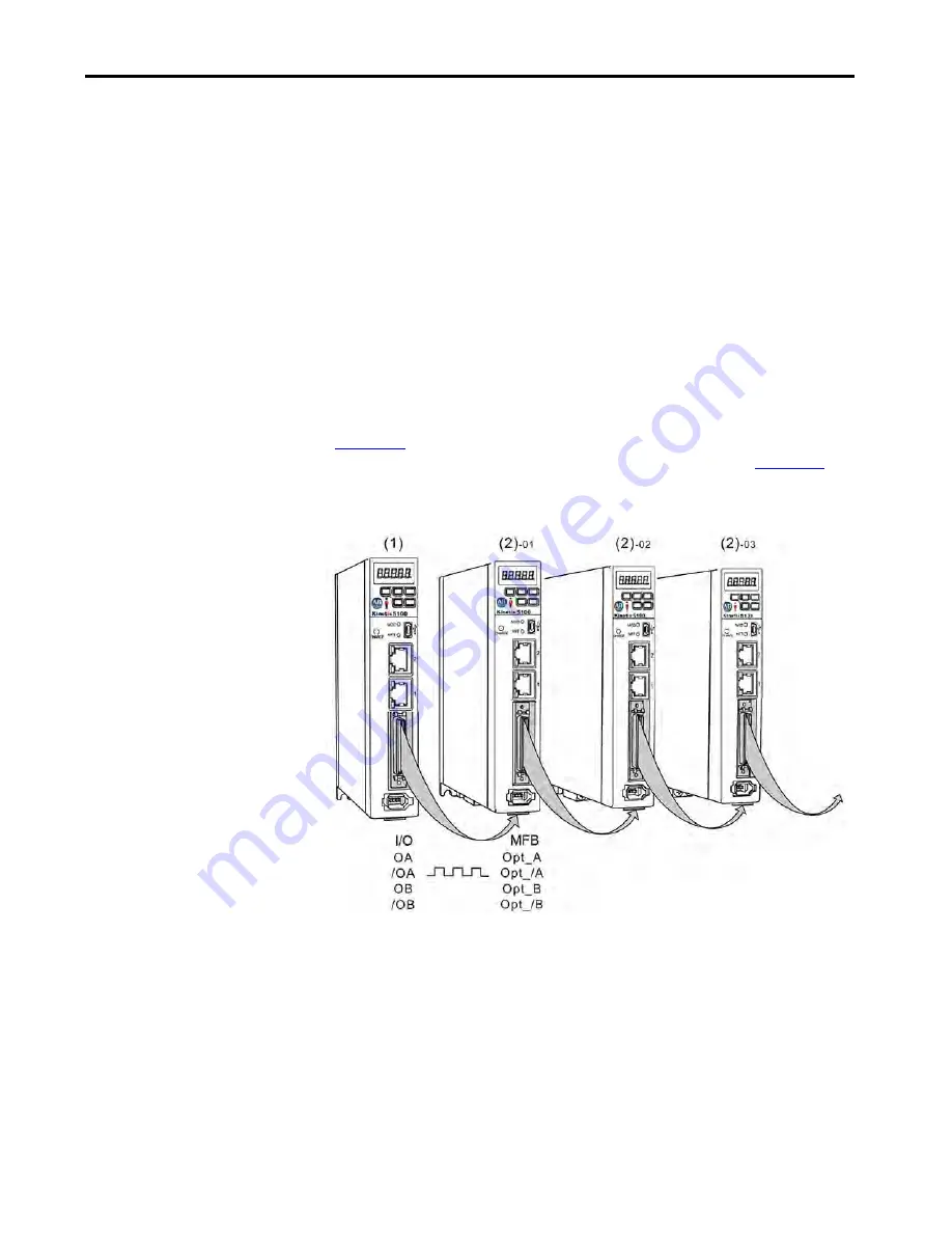
(P1.074.Y). If the MFB connector is used as the pulse input channel, as shown in
, then the value of ID173 (P1.074.Y) of each drive shall be set to 1. If
the I/O connector is used as the pulse input channel, as shown in
then the value of ID173 (P1.074.Y) of each drive is set to 2.
Figure 163 - Pulse By-pass Function - Motor Feedback (MFB) Connector
Summary of Contents for Kinetix 5100 2198-E1004-ERS
Page 499: ......