


Rockwell Automation Publication 1440-UM001D-EN-P - September 2016
85
Configure the XM-124 Standard Dynamic Measurement Module
Chapter 2
Alert Threshold (High)
The threshold value for the alert (alarm) condition.
IMPORTANT: This parameter is the greater threshold value when
Condition is set to ‘Inside Range’ or ‘Outside Range,’ the measurement is
a phase measurement (Configuration Utility), or the alarm type is a
vector alarm (EDS file).
Same measurement unit as Output Data Unit
selection for the specified channel except when
measurement/alarm type is phase (vector).
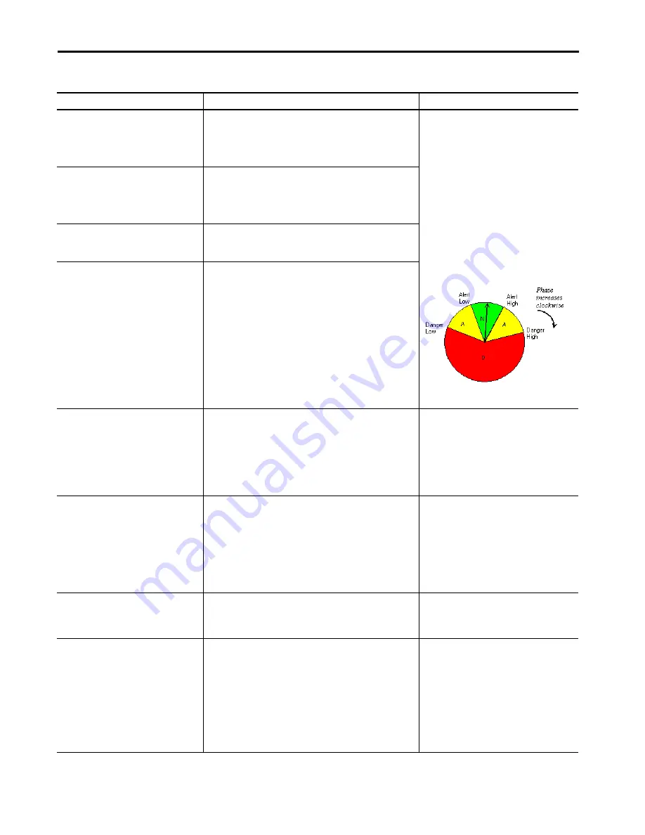
Phase Measurements/Vector Alarm Type
Requirements:
• The Alert Low, Danger Low, Alert High, and
Danger High must define contiguous sections
within the set of possible phase values (0…360
degrees).
• If you plot the thresholds on a clock face
(illustration with phase increasing in the
clockwise direction, then adjust these settings:
– Alert Low must be clockwise from or equal to
Danger Low.
– Alert High must be clockwise from Alert Low.
– Danger High must be clockwise from or equal
to Alert High.
Danger Threshold (High)
The threshold value for the danger (shutdown) condition.
IMPORTANT: This parameter is the greater threshold value when
Condition is set to ‘Inside Range’ or ‘Outside Range,’ the measurement is
a phase measurement (Configuration Utility), or the alarm type is a
vector alarm (EDS file).
Alert Threshold (Low)
The lesser threshold value for the alert (alarm) condition.
IMPORTANT:
This parameter is not used when Condition is set to ‘Greater
Than’ or ‘Less Than.’
Danger Threshold (Low)
The lesser threshold value for the danger (shutdown) condition.
IMPORTANT:
This parameter is not used when Condition is set to ‘Greater
Than’ or ‘Less Than.’
Hysteresis
The amount that the measured value must fall (below the threshold)
before the alarm condition is cleared. For example, Alert Threshold =
120 and Hysteresis = 2. The alarm (alert) activates when the measured
value is 120 and does not clear until the measured value is 118.
IMPORTANT: The Alert and Danger Thresholds use the same hysteresis
value.
IMPORTANT: For the Outside Range condition, the hysteresis value must
be less than Alert Threshold (High) – Alert Threshold (Low).
Same measurement unit as Output Data Unit
selection for the specified channel
.
Detection Delay
Enter the length of time for which the Alarm Condition must persist
before the alarm is signaled.
Applying delays can reduce nuisance alarms caused by external noise
and/or transient vibration events.
IMPORTANT: Delays can also be applied as part of the Relay definition.
Delays there are associated with the Relay Activation Logic, and only
begin once any Alarm condition is signaled. Consequently, applying
delays to both the Alarm and Relay results in a total delay time, before
relay actuation, which is the sum of the alarm and relay delay times.
Enter a value 0…65.5 seconds.
Start-up Period
The length of time that the Threshold Multiplier is applied to the
thresholds. The start-up period begins when the setpoint multiplier
switch is reopened (push button disengaged or toggle switch flipped to
off).
Enter a value from 0…1092 minutes, adjustable in
increments of 0.1 minutes.
Threshold Multiplier
The action to take when the setpoint multiplier switch is closed (push
button engaged or toggle switch flipped to on) and during the start-up
period once the switch is reopened. The module applies the multiplier
to the alarm thresholds during this time to avoid false alarms at
resonance frequencies.
IMPORTANT: The multiplication can have the opposite of the intended
effect under certain circumstances. For example, if the Condition is set
to ‘Less Than’ and the thresholds are positive, then multiplication of the
threshold values increases the likelihood of the measured value being
within the alarm range. Therefore, it can be beneficial to set Threshold
Multiplier to zero to disable the alarm during the start-up period.
Enter a floating point value in the range of 0…10.
Enter 0 (zero) to disable the alarm during the start-
up period.
Table 15 - Alarm Parameters (Continued)
Parameter Name
Description
Values/Comments
Summary of Contents for 1440-SDM02-01RA
Page 8: ...8 Rockwell Automation Publication 1440 UM001D EN P September 2016 Table of Contents Notes...
Page 10: ...10 Rockwell Automation Publication 1440 UM001D EN P September 2016 Summary of Changes Notes...
Page 12: ...12 Rockwell Automation Publication 1440 UM001D EN P September 2016 Preface Notes...
Page 167: ......