233
Theory of Operation
Interfaces
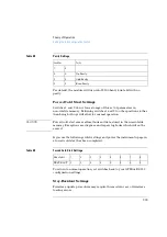
To provide maximum safety within a distributed analysis system, one line
is dedicated to SHUT DOWN the system’s critical parts in case any module
detects a serious problem. To detect whether all participating modules are
switched on or properly powered, one line is defined to summarize the
POWER ON state of all connected modules. Control of analysis is
maintained by signal readiness READY for next analysis, followed by
START of run and optional STOP of run triggered on the respective lines.
In addition, PREPARE and START REQUEST may be issued. The signal
level is defined as:
•
standard TTL levels (0 V is logic true, + 5 V is false),
•
fan-out is 10,
•
input load is 2.2 kOhm a 5 V, and
•
outputs are open collector type, inputs/outputs (wired-or technique).
Summary of Contents for G1313A
Page 1: ...s1 Agilent 1100 Series Standard Micro and Preparative Autosamplers Reference Manual ...
Page 3: ...Reference Manual Agilent 1100 Series Standard Micro and Preparative Autosamplers ...
Page 12: ...12 Contents ...
Page 39: ...2 2 Optimizing Performance How to optimize the autosamplers to achieve best results ...
Page 93: ...93 Troubleshooting and Test Functions Step Commands ...
Page 216: ...216 Introduction to the Autosampler Electrical Connections ...
Page 244: ...244 Theory of Operation The Main Power Supply Assembly ...
Page 265: ...265 Introduction to the Control Module Diagnostics and Tests ...
Page 268: ...268 Introduction to the Control Module Diagnostics and Tests ...
Page 274: ...274 Specifications Performance Specifications ...
Page 275: ...10 Legal Safety and Warranty Information ...
Page 286: ...286 Agilent Technologies on Internet ...
Page 290: ...290 Index ...
Page 291: ......


