223
Theory of Operation
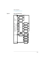
Autosampler Main Board (ASM)
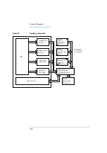
Figure 38
Transport unit control
Sampling Unit Control
Needle arm, metering device and valve motors are driven by controlled
pulse-width modulation in the same way as the SGS L6506 (see “Transport
Unit Control” on page 221). The motors require fast speed but do not
require precise position control. Therefore, a closed loop servo system is
not required. Commutation is done in FPGA logic. The needle arm,
metering device and valve motors use SGS L6203 output drivers to deliver
the higher currents required for fast movement or high torque.
The movement sensing of the valve motor is done by two microswitches.
Two reflection light sensors are used to detect the end positions of the
needle arm. One photo sensor is required to detect the home position of
the metering device. Two hall sensors detect correct closure of the door
(needle arm movement is interrupted if the door is open). All the sensors
are mounted on one flex board. The flex board and motors are connected
to the sampling unit distribution board (SUD). The SUD board is
connected to the autosampler main board (ASM) via a flat-band cable (64
pin).
FPGA
Theta Drive
Gripper Drive
X-Axis Drive
Z-Axis Drive
ASIC
Motor
Encoder
Motor
Encoder
Motor
Encoder
Motor
Encoder
Via transport
unit flex board
Reflection sensors on transport unit flex board:
Tray decoding (6), gripper decoding (1), initialization sensors
(3).
Summary of Contents for G1313A
Page 1: ...s1 Agilent 1100 Series Standard Micro and Preparative Autosamplers Reference Manual ...
Page 3: ...Reference Manual Agilent 1100 Series Standard Micro and Preparative Autosamplers ...
Page 12: ...12 Contents ...
Page 39: ...2 2 Optimizing Performance How to optimize the autosamplers to achieve best results ...
Page 93: ...93 Troubleshooting and Test Functions Step Commands ...
Page 216: ...216 Introduction to the Autosampler Electrical Connections ...
Page 244: ...244 Theory of Operation The Main Power Supply Assembly ...
Page 265: ...265 Introduction to the Control Module Diagnostics and Tests ...
Page 268: ...268 Introduction to the Control Module Diagnostics and Tests ...
Page 274: ...274 Specifications Performance Specifications ...
Page 275: ...10 Legal Safety and Warranty Information ...
Page 286: ...286 Agilent Technologies on Internet ...
Page 290: ...290 Index ...
Page 291: ......


