192
Parts and Materials
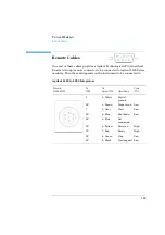
Remote Cables
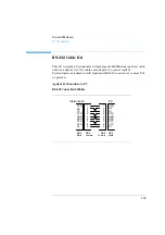
Agilent 1100 to 3396A Integrators
Agilent 1100 to 3396 Series II / 3395A Integrators
Use the cable 03394-60600 and cut pin #5 on the integrator side.
Otherwise the integrator prints START; not ready.
Connector
03394-60600
Pin
3394
Pin
Agilent 1100
Signal Name
Active
(TTL)
9
1 - White
Digital
ground
NC2 - Brown
Prepare run
Low
3
3 - Gray
Start
Low
NC4 - Blue
Shut down
Low
NC5 - Pink
Not
connected
NC6 - Yellow
Power on
High
5,14
7 - Red
Ready
High
1
8 - Green
Stop
Low
NC9 - Black
Start request Low
13, 15
Not
connected
Summary of Contents for G1313A
Page 1: ...s1 Agilent 1100 Series Standard Micro and Preparative Autosamplers Reference Manual ...
Page 3: ...Reference Manual Agilent 1100 Series Standard Micro and Preparative Autosamplers ...
Page 12: ...12 Contents ...
Page 39: ...2 2 Optimizing Performance How to optimize the autosamplers to achieve best results ...
Page 93: ...93 Troubleshooting and Test Functions Step Commands ...
Page 216: ...216 Introduction to the Autosampler Electrical Connections ...
Page 244: ...244 Theory of Operation The Main Power Supply Assembly ...
Page 265: ...265 Introduction to the Control Module Diagnostics and Tests ...
Page 268: ...268 Introduction to the Control Module Diagnostics and Tests ...
Page 274: ...274 Specifications Performance Specifications ...
Page 275: ...10 Legal Safety and Warranty Information ...
Page 286: ...286 Agilent Technologies on Internet ...
Page 290: ...290 Index ...
Page 291: ......

