15
Installing the Autosampler
Site Requirements
Power Cords
Your autosampler is delivered with a power cord which matches the wall
socket of your particular country or region. The plug on the power cord
which connects to the rear of the instrument is identical for all types of
power cord.
WA R N I N G
Never operate your instrumentation from a power outlet that has no
ground connection. Never use a power cord other than the power cord
designed for your region.
WA R N I N G
Never use cables other than the ones supplied by Agilent Technologies
to ensure proper functionality and compliance with safety or EMC
regulations.
Bench Space
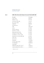
The autosampler dimensions and weight (see Table 1) allow the
instrument to be placed on almost any laboratory bench. The instrument
requires an additional 2.5 cm (1.0 inch) of space on either side, and
approximately 8 cm (3.1 inches) at the rear for the circulation of air, and
room for electrical connections. Ensure the autosampler is installed in a
horizontal position.
The thermostatted autosampler dimensions and weight (see ) allow the
instrument to be placed on almost any laboratory bench. The instrument
requires an additional 25 cm (10 inches) of space on either side for the
circulation of air, and approximately 8 cm (3.1 inches) at the rear for
electrical connections. Ensure the autosampler is installed in a level
position.
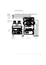
If a complete Agilent 1100 Series system is to be installed on the bench,
make sure that the bench is designed to carry the weight of all the
modules. For a complete system including the thermostatted autosampler
it is recommended to position the modules in two stacks, see “Optimizing
the Stack Configuration” on page 22. Make sure that in this configuration
there is 25 cm (10 inches) space on either side of the thermostatted
autosampler for the circulation of air.
Summary of Contents for G1313A
Page 1: ...s1 Agilent 1100 Series Standard Micro and Preparative Autosamplers Reference Manual ...
Page 3: ...Reference Manual Agilent 1100 Series Standard Micro and Preparative Autosamplers ...
Page 12: ...12 Contents ...
Page 39: ...2 2 Optimizing Performance How to optimize the autosamplers to achieve best results ...
Page 93: ...93 Troubleshooting and Test Functions Step Commands ...
Page 216: ...216 Introduction to the Autosampler Electrical Connections ...
Page 244: ...244 Theory of Operation The Main Power Supply Assembly ...
Page 265: ...265 Introduction to the Control Module Diagnostics and Tests ...
Page 268: ...268 Introduction to the Control Module Diagnostics and Tests ...
Page 274: ...274 Specifications Performance Specifications ...
Page 275: ...10 Legal Safety and Warranty Information ...
Page 286: ...286 Agilent Technologies on Internet ...
Page 290: ...290 Index ...
Page 291: ......


