153
Repairing the Autosampler
SUD Board
4
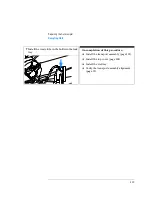
Secure the board in place with the two
screws.
5
Reconnect all the connectors to the new
board.
On completion of this procedure:
❏
Install the sampling unit (page 134).
❏
Install the transport assembly (page 132).
❏
Install the top cover (page 128).
❏
Verify the transport assembly alignment (page 99).
Fixing screws
Leak sensor
Metering drive
Injection
Valve
Needle drive
Flex board
Summary of Contents for G1313A
Page 1: ...s1 Agilent 1100 Series Standard Micro and Preparative Autosamplers Reference Manual ...
Page 3: ...Reference Manual Agilent 1100 Series Standard Micro and Preparative Autosamplers ...
Page 12: ...12 Contents ...
Page 39: ...2 2 Optimizing Performance How to optimize the autosamplers to achieve best results ...
Page 93: ...93 Troubleshooting and Test Functions Step Commands ...
Page 216: ...216 Introduction to the Autosampler Electrical Connections ...
Page 244: ...244 Theory of Operation The Main Power Supply Assembly ...
Page 265: ...265 Introduction to the Control Module Diagnostics and Tests ...
Page 268: ...268 Introduction to the Control Module Diagnostics and Tests ...
Page 274: ...274 Specifications Performance Specifications ...
Page 275: ...10 Legal Safety and Warranty Information ...
Page 286: ...286 Agilent Technologies on Internet ...
Page 290: ...290 Index ...
Page 291: ......


