


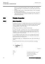
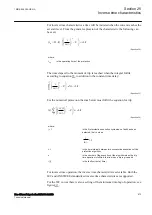


For inverse time characteristics a time will be initiated when the current reaches the
set start level. From the general expression of the characteristic the following can
be seen:
(
)
- × ×
-
= ×
>
æ
ö
æ
ö
ç
÷
ç
÷
è
ø
è
ø
p
op
i
t
B k
C
A k
in
EQUATION1190 V1 EN-US
(Equation 94)
where:
t
op
is the operating time of the protection
The time elapsed to the moment of trip is reached when the integral fulfils
according to equation
, in addition to the constant time delay:
0
-
×
³ ×
>
æ
ö
æ
ö
ç
÷
ç
÷
è
ø
è
ø
ò
p
t
i
C
dt
A k
in
EQUATION1191 V1 EN-US
(Equation 95)
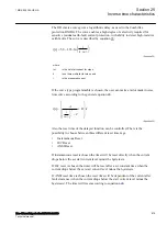
For the numerical protection the sum below must fulfil the equation for trip.
1
( )
=
D ×
-
³ ×
>
æ
ö
æ
ö
ç
÷
ç
÷
è
ø
è
ø
å
p
n
j
i j
t
C
A k
in
EQUATION1192 V1 EN-US
(Equation 96)
where:
j = 1
is the first protection execution cycle when a fault has been
detected, that is, when
1
i
in
>
>
EQUATION1193 V1 EN-US
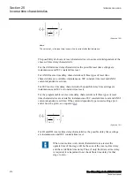
D
t
is the time interval between two consecutive executions of the
protection algorithm,
n
is the number of the execution of the algorithm when the trip
time equation is fulfilled, that is, when a trip is given and
i (j)
is the fault current at time j
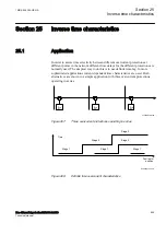
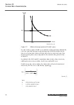
For inverse time operation, the inverse time characteristic is selectable. Both the
IEC and ANSI/IEEE standardized inverse time characteristics are supported.
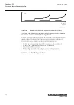
For the IEC curves there is also a setting of the minimum time-lag of operation, see
figure
.
1MRK 505 394-UEN A
Section 25
Inverse time characteristics
Line differential protection RED650 2.2 IEC
873
Technical manual
Summary of Contents for RED650
Page 1: ...RELION 650 SERIES Line differential protection RED650 Version 2 2 Technical manual...
Page 2: ......
Page 36: ...30...
Page 46: ...40...
Page 232: ...226...
Page 272: ...266...
Page 288: ...282...
Page 306: ...300...
Page 406: ...400...
Page 436: ...430...
Page 502: ...496...
Page 614: ...608...
Page 628: ...622...
Page 644: ...638...
Page 760: ...754...
Page 778: ...772...
Page 814: ...808...
Page 870: ...864...
Page 874: ...868...
Page 924: ...918...
Page 925: ...919...


