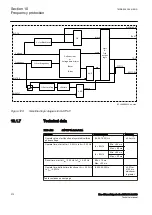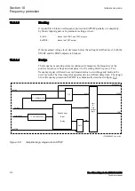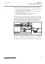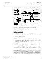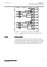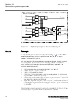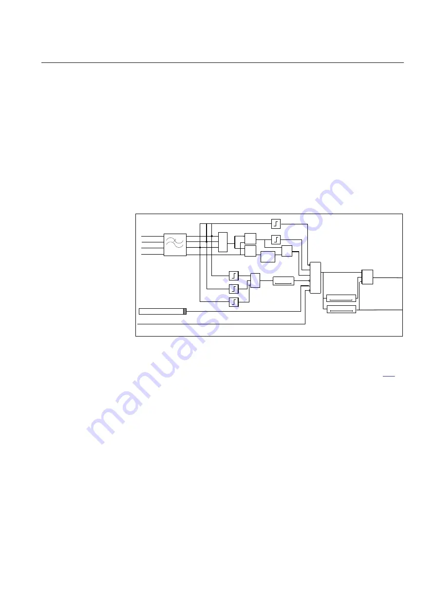
The FAIL output will be set to high when the following criteria are fulfilled:
•
The numerical value of the difference |ΣIphase| – |Iref| is higher than 80% of
the numerical value of the sum |ΣIphase| + |Iref|.
•
The numerical value of the current |ΣIphase| – |Iref| is equal to or higher than
the set operate value
IMinOp
.
•
No phase current has exceeded
Ip>Block
during the last 10 ms.
•
CCSSPVC is enabled by setting
Operation
=
On
.
The FAIL output remains activated 100 ms after the AND-gate resets when being
activated for more than 20 ms. If the FAIL lasts for more than 150 ms an ALARM
will be issued. In this case the FAIL and ALARM will remain activated 1 s after
the AND-gate resets. This prevents unwanted resetting of the blocking function
when phase current supervision element(s) operate, for example, during a fault.
å
IL1
IL2
IL3
Iref
å
+
-
å
+
+
I>IMinOp
å
+
-
x
0,8
AND
BLOCK
1,5 x Ir
10 ms
OPERATION
100 ms
1 s
150 ms
20 ms
I>
Ip>Block
en05000463.tif
FAIL
ALARM
IL1
IL2
IL3
Iref
BLOCK
OR
IEC05000463 V2 EN-US
Figure 134:
Simplified logic diagram for Current circuit supervision CCSSPVC
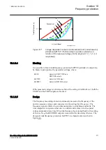
The operate characteristic is percentage restrained, which is shown in Figure
1MRK 505 394-UEN A
Section 11
Secondary system supervision
Line differential protection RED650 2.2 IEC
285
Technical manual
Summary of Contents for RED650
Page 1: ...RELION 650 SERIES Line differential protection RED650 Version 2 2 Technical manual...
Page 2: ......
Page 36: ...30...
Page 46: ...40...
Page 232: ...226...
Page 272: ...266...
Page 288: ...282...
Page 306: ...300...
Page 406: ...400...
Page 436: ...430...
Page 502: ...496...
Page 614: ...608...
Page 628: ...622...
Page 644: ...638...
Page 760: ...754...
Page 778: ...772...
Page 814: ...808...
Page 870: ...864...
Page 874: ...868...
Page 924: ...918...
Page 925: ...919...

