

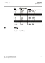


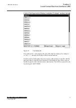


The CT and VT ratio and the name on respective channel is done under
IED
Configuration/HW Configuration/ADM
in the Parameter Settings Tool or under
Main menu/Configuration/Analog modules
in the HMI.
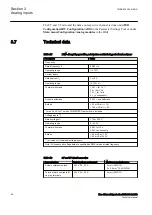
3.7
Technical data
SEMOD55412-1 v1
M16988-1 v11
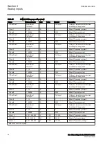
Table 17:
TRM - Energizing quantities, rated values and limits for protection transformer
Description
Value
Frequency
Rated frequency f
r
50/60 Hz
Operating range
f
r
± 10%
Current inputs
Rated current I
r
1 or 5 A
Operating range
(0-100) x I
r
Thermal withstand
100 × I
r
for 1 s *)
30 × I
r
for 10 s
10 × I
r
for 1 min
4 × I
r
continuously
Dynamic withstand
250 × I
r
one half wave
Burden
< 20 mVA at I
r
= 1 A
< 150 mVA at I
r
= 5 A
*) max. 350 A for 1 s when COMBITEST test switch is included.
Voltage inputs **)
Rated voltage U
r
110 or 220 V
Operating range
0 - 340 V
Thermal withstand
450 V for 10 s
420 V continuously
Burden
< 20 mVA at 110 V
< 80 mVA at 220 V
**) all values for individual voltage inputs
Note! All current and voltage data are specified as RMS values at rated frequency
SEMOD53376-2 v6
Table 18:
CT and VT circuit connectors
Connector type
Rated voltage and current
Maximum conductor area
Screw compression type
250 V AC, 20 A
4 mm
2
(AWG12)
2 x 2.5 mm
2
(2 x AWG14)
Terminal blocks suitable for
ring lug terminals
250 V AC, 20 A
4 mm
2
(AWG12)
Section 3
1MRK 505 394-UEN A
Analog inputs
58
Line differential protection RED650 2.2 IEC
Technical manual
Summary of Contents for RED650
Page 1: ...RELION 650 SERIES Line differential protection RED650 Version 2 2 Technical manual...
Page 2: ......
Page 36: ...30...
Page 46: ...40...
Page 232: ...226...
Page 272: ...266...
Page 288: ...282...
Page 306: ...300...
Page 406: ...400...
Page 436: ...430...
Page 502: ...496...
Page 614: ...608...
Page 628: ...622...
Page 644: ...638...
Page 760: ...754...
Page 778: ...772...
Page 814: ...808...
Page 870: ...864...
Page 874: ...868...
Page 924: ...918...
Page 925: ...919...