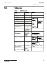
Name
Values (Range)
Unit
Step
Default
Description
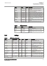
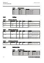
kLdRFw
0.50 - 0.90
Mult
0.01
0.75
Multiplication factor for inner resistive
load boundary, forward
kLdRRv
0.50 - 0.90
Mult
0.01
0.75
Multiplication factor for inner resistive
load boundary, reverse
tEF
0.000 - 60.000
s
0.001
3.000
Timer for overcoming single-pole
reclosing dead time
IMinOpPE
5 - 30
%IB
1
10
Minimum operate current in % of IBase
Table 52:
ZMRPSB Group settings (advanced)
Name
Values (Range)
Unit
Step
Default
Description
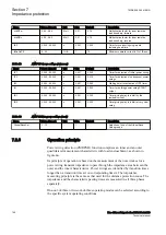
tP1
0.000 - 60.000
s
0.001
0.045
Timer for detection of initial power swing
tP2
0.000 - 60.000
s
0.001
0.015
Timer for detection of subsequent power
swings
tW
0.000 - 60.000
s
0.001
0.250
Waiting timer for activation of tP2 timer
tH
0.000 - 60.000
s
0.001
0.500
Timer for holding power swing START
output
tR1
0.000 - 60.000
s
0.001
0.300
Timer giving delay to inhibit by the
residual current
tR2
0.000 - 60.000
s
0.001
2.000
Timer giving delay to inhibit at very slow
swing
Table 53:
ZMRPSB Non group settings (basic)
Name
Values (Range)
Unit
Step
Default
Description
GlobalBaseSel
1 - 12
-
1
1
Selection of one of the Global Base
Value groups
7.2.6
Operation principle
M13877-4 v4
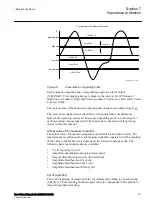
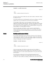
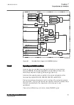
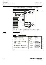
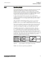
Power swing detection (ZMRPSB ) function comprises an inner and an outer
quadrilateral measurement characteristic with load encroachment, as shown in
figure
.
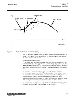
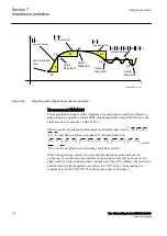
Its principle of operation is based on the measurement of the time it takes for a
power swing transient impedance to pass through the impedance area between the
outer and the inner characteristics. Power swings are identified by transition times
longer than a transition time set on corresponding timers. The impedance
measuring principle is the same as that used for the distance protection zones. The
impedance and the characteristic passing times are measured in all three phases
separately.
One-out-of-three or two-out-of-three operating modes can be selected according to
the specific system operating conditions.
Section 7
1MRK 505 394-UEN A
Impedance protection
148
Line differential protection RED650 2.2 IEC
Technical manual
Summary of Contents for RED650
Page 1: ...RELION 650 SERIES Line differential protection RED650 Version 2 2 Technical manual...
Page 2: ......
Page 36: ...30...
Page 46: ...40...
Page 232: ...226...
Page 272: ...266...
Page 288: ...282...
Page 306: ...300...
Page 406: ...400...
Page 436: ...430...
Page 502: ...496...
Page 614: ...608...
Page 628: ...622...
Page 644: ...638...
Page 760: ...754...
Page 778: ...772...
Page 814: ...808...
Page 870: ...864...
Page 874: ...868...
Page 924: ...918...
Page 925: ...919...


