
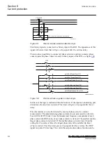


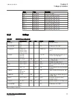
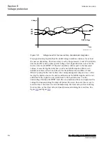

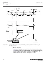
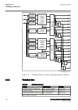


Voltage
IDMT Voltage
Time
UL1
UL2
UL3
IEC12000186-1-en.vsd
IEC12000186 V1 EN-US
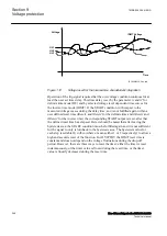
Figure 103:
Voltage used for the inverse time characteristic integration
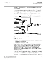
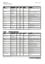
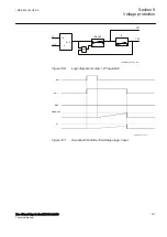
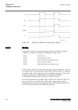
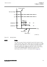
Trip signal issuing requires that the undervoltage condition continues for at least
the user set time delay. This time delay is set by the parameter
t1
and
t2
for definite
time mode (DT) and by some special voltage level dependent time curves for the
inverse time mode (IDMT). If the start condition, with respect to the measured
voltage, ceases during the delay time, and is not fulfilled again within a user-
defined reset time (
tReset1
and
tReset2
for the definite time and
tIReset1
and
tIReset2
pickup for the inverse time) the corresponding start output is reset. After
leaving the hysteresis area, the start condition must be fulfilled again and it is not
sufficient for the signal to only return back to the hysteresis area. For the
undervoltage function the IDMT reset time is constant and does not depend on the
voltage fluctuations during the drop-off period. However, there are three ways to
reset the timer: the timer is reset instantaneously, the timer value is frozen during
the reset time, or the timer value is linearly decreased during the reset time. See
figure
and figure
Section 9
1MRK 505 394-UEN A
Voltage protection
234
Line differential protection RED650 2.2 IEC
Technical manual
Summary of Contents for RED650
Page 1: ...RELION 650 SERIES Line differential protection RED650 Version 2 2 Technical manual...
Page 2: ......
Page 36: ...30...
Page 46: ...40...
Page 232: ...226...
Page 272: ...266...
Page 288: ...282...
Page 306: ...300...
Page 406: ...400...
Page 436: ...430...
Page 502: ...496...
Page 614: ...608...
Page 628: ...622...
Page 644: ...638...
Page 760: ...754...
Page 778: ...772...
Page 814: ...808...
Page 870: ...864...
Page 874: ...868...
Page 924: ...918...
Page 925: ...919...


