


1
L
U
set
N
Z
K
I
1
0
3
set
N
L
L
comp
Z
K
I
I
U
U
1
)
0
3
(
1
1
pol
U
I
L1
•R
I
L1
•jX
set
L
Z
I
1
1
IEC15000059-1-en.vsdx
IEC15000059 V1 EN-US
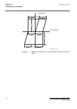
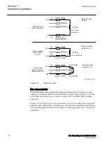
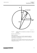
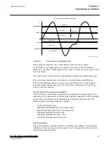
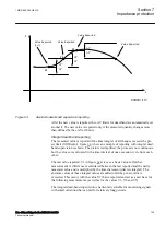
Figure 51:
Simplified offset mho characteristic and vector diagram for phase
L1-to-earth fault
Operation occurs if 90°≤β≤270°.
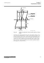
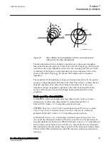
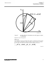
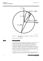
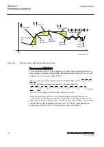
Offset mho
GUID-B1EF3931-7B86-4C7B-BCEA-3034482BA240 v2
The condition for operation of offset mho at phase-to-earth fault is that the angle β
between the two compensated voltages is equal to or greater than 90°, see figure
. The angle will be 90° for fault location on the boundary of the circle.
1
1
1
1
arg
(
3 0
)
1
arg
(
3 0
)
1
L
L
N
set
L
L
N
set
U
I
I
K
Z
U
I
I
K
Z
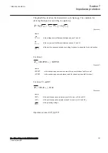
IECEQUATION15022 V2 EN-US
(Equation 12)
1MRK 505 394-UEN A
Section 7
Impedance protection
Line differential protection RED650 2.2 IEC
131
Technical manual
Summary of Contents for RED650
Page 1: ...RELION 650 SERIES Line differential protection RED650 Version 2 2 Technical manual...
Page 2: ......
Page 36: ...30...
Page 46: ...40...
Page 232: ...226...
Page 272: ...266...
Page 288: ...282...
Page 306: ...300...
Page 406: ...400...
Page 436: ...430...
Page 502: ...496...
Page 614: ...608...
Page 628: ...622...
Page 644: ...638...
Page 760: ...754...
Page 778: ...772...
Page 814: ...808...
Page 870: ...864...
Page 874: ...868...
Page 924: ...918...
Page 925: ...919...