


When the automatic reset of the LEDs has been performed, still
persisting indications will be indicated with a steady light.
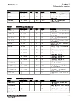
Operating sequence
GUID-DFCA880B-308C-4334-94DF-97C7765E8C13 v5
The sequences can be of type Follow or Latched. For the Follow type, the LED
follows the input signal completely. For the Latched type, each LED latches to the
corresponding input signal until it is reset.
The figures below show the function of available sequences selectable for each
LED separately. The following 6 sequences are available:
•
Sequence 1: Follow-S
•
Sequence 2: Follow-F
•
Sequence 3: LatchedAck-F-S
•
Sequence 4: LatchedAck-S-F
•
Sequence 5: LatchedColl-S
•
Sequence 6: LatchedReset-S
For
sequence 1
and
2
, which are of the Follow type, the acknowledgment (Ack ) /
reset function is not applicable because the indication shown by the LED follows
its input signal.
Sequence 3
and
4
, which are of the Latched type with
acknowledgement, are only working in collecting (Coll) mode.
Sequence 5
is
working according to Latched type and collecting mode while
Sequence 6
is
working according to Latched type and re-starting (Reset) mode. The letters
S
and
F
in the sequence names have the meaning
S
= Steady and
F
= Flash.
At the activation of the input signal to any LED, the indication on the
corresponding LED obtains a color that corresponds to the activated input, and
operates according to the selected sequence diagrams shown below.
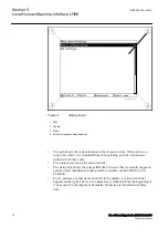
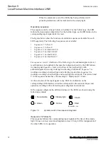
In the sequence diagrams the different statuses of the LEDs are shown using the
following symbols:
= No indication
= Steady light
= Flash
G
= Green
Y
= Yellow
R
= Red
IEC09000311.vsd
IEC09000311 V1 EN-US
Figure 14:
Symbols used in the sequence diagrams
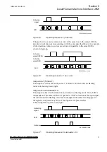
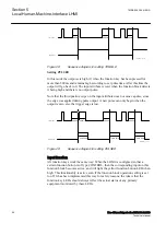
Sequence 1
(Follow-S)
SEMOD56072-39 v4
This sequence follows the corresponding input signals all the time with a steady
light. It does not react on acknowledgment or reset. Every LED is independent of
the other LEDs in its operation.
Section 5
1MRK 505 394-UEN A
Local Human-Machine-Interface LHMI
76
Line differential protection RED650 2.2 IEC
Technical manual
Summary of Contents for RED650
Page 1: ...RELION 650 SERIES Line differential protection RED650 Version 2 2 Technical manual...
Page 2: ......
Page 36: ...30...
Page 46: ...40...
Page 232: ...226...
Page 272: ...266...
Page 288: ...282...
Page 306: ...300...
Page 406: ...400...
Page 436: ...430...
Page 502: ...496...
Page 614: ...608...
Page 628: ...622...
Page 644: ...638...
Page 760: ...754...
Page 778: ...772...
Page 814: ...808...
Page 870: ...864...
Page 874: ...868...
Page 924: ...918...
Page 925: ...919...