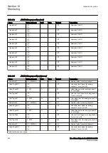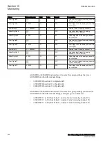
Inactive timer
The Inactive timer module calculates the number of days the circuit breaker has
remained in the same open or closed state. The value is calculated by monitoring
the states of the
POSOPEN
and
POSCLOSE
auxiliary contacts.
The number of inactive days
INADAYS
is available as a service value. The initial
number of inactive days is set using the
InitInactDays
parameter.
Alarm limit check
MONALM
is initiated when the number of inactive days and hours exceed the limit
value defined by the
InactiveAlDays
and
InactivAlHrs
setting. The alarm signal
MONALM
can be blocked by activating the binary input
BLKALM
.
15.4.7.7
Circuit breaker spring charge monitoring
GUID-F850A940-7890-4C37-8B31-6C7D5B30E582 v11
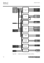
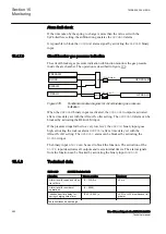
The circuit breaker spring charge monitoring subfunction calculates the spring
charging time. The operation is described in figure
.
SPRCHRD
BLOCK
BLKALM
Spring charging
time
measurement
Alarm limit
Check
SPRCHRST
RSTSPCHT
SPCHT
SPCHALM
IEC12000621 V2 EN-US
Figure 277:
Functional module diagram for circuit breaker spring charge
indication
Spring charging time measurement
Spring charging time calculation will be initiated as soon as the circuit breaker is
closed and charging motor starts (
NO
contact of the device is connected to
SPRCHRST
) to store the energy in the close spring. An indicator provided in the
circuit breaker is displayed when the spring is completely charged. This status is
taken through
NO
contact and then connected to
SPRCHRD
.
The binary input
SPRCHRST
indicates the start of circuit breaker spring charging
time.
SPRCHRD
indicates that the circuit breaker spring is charged. The spring
charging time is calculated from the difference of these two signal timings. Spring
charging indication is described in figure
The last measured spring charging time
SPCHT
is provided as a service value. The
spring charging time
SPCHT
can be reset on the LHMI or by activating the input
RSTSPCHT
.
1MRK 505 394-UEN A
Section 15
Monitoring
Line differential protection RED650 2.2 IEC
551
Technical manual
Summary of Contents for RED650
Page 1: ...RELION 650 SERIES Line differential protection RED650 Version 2 2 Technical manual...
Page 2: ......
Page 36: ...30...
Page 46: ...40...
Page 232: ...226...
Page 272: ...266...
Page 288: ...282...
Page 306: ...300...
Page 406: ...400...
Page 436: ...430...
Page 502: ...496...
Page 614: ...608...
Page 628: ...622...
Page 644: ...638...
Page 760: ...754...
Page 778: ...772...
Page 814: ...808...
Page 870: ...864...
Page 874: ...868...
Page 924: ...918...
Page 925: ...919...

